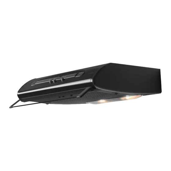
Electrolux DVK5510SW Manuel D'instructions
Masquer les pouces Voir aussi pour DVK5510SW:

Publicité

Les langues disponibles

Les langues disponibles

Liens rapides

DE
FR
IT
GB
DVK5510SW - DVK5510WE - DVK5510BR
DVK6010SW - DVK6010WE - DVK6010BR
DVK5511SW - DVK5511BR - DVK6011WE
DVK5511WE - DVK6011SW - DVK6011BR
Bedienungsanleitung
Manuel d'Instructions
Libretto Istruzioni
Instruction Manual

Publicité

Table des Matières
loading

Sommaire des Matières pour Electrolux DVK5510SW

  • Page 1 Bedienungsanleitung Manuel d’Instructions Libretto Istruzioni Instruction Manual DVK5510SW - DVK5510WE - DVK5510BR DVK6010SW - DVK6010WE - DVK6010BR DVK5511SW - DVK5511BR - DVK6011WE DVK5511WE - DVK6011SW - DVK6011BR...
  • Page 2: Table Des Matières

    1-2. EMPFEHLUNGEN UND HINWEISE .................. 3 3. MONTAGE ..........................6 4. SICHERHEITSHINWEISE ....................... 8 5. BEDIENUNG ..........................8 6. WARTUNG ..........................9 1-2. CONSEILS ET SUGGESTIONS ..................11 3. INSTALLATION ........................14 4. CONSEILS CONCERNANT LA SECURITE ............... 16 5. UTILISATION ..........................16 6.
  • Page 3: Empfehlungen Und Hinweise

    1-2. EMPFEHLUNGEN UND HINWEISE MONTAGE triebene Geräte (zum Beispiel Gasgeräte) eingesetzt werden, • Diese Gebrauchsanleitungen be- muss für eine ausreichende Be- ziehensichauf dieverschiedenen lüftung gesorgt werden, damit der Modelle der Abzugshaube. Dar- Rückfluss der Abgase verhindert um kann es möglich sein, dass wird.
  • Page 4 GEBRAUCH WARTUNG • Die Abzugshaube wurde aus- • Das Symbol am Produkt oder schließlich für den häuslichen auf der Verpackung weist dar- Gebrauch entwickelt, um Koch- auf hin, dass das Gerät nicht dünste zu beseitigen. als normaler Hausmüll entsorgt • Die Haube darf nur für die ihr werden darf.
  • Page 5 - Die Fettfilter sind alle 2 Monate oder bei intensiver Nutzung öfter zu reinigen und können in der Spülmaschine gespült werden (Z). - Kontrolllampen der Steuerun- gen, wo vorhanden. • Die Haube mit einem feuchten Lappen und einem neutralen Reinigungsmittel abwischen.
  • Page 6: Montage

    3. MONTAGE 3.1 - Installierung der Rückwand Vor der Installierung der Haube, es ist möglich, die mitgelieferte Rückwand zu installieren. • Die Befestigungslöcher die Wand aufzeichnen, wie in der Abb A. • Die Wand bohren (2 Löcher Ø 5mm) und die Dübel einsetzen. • Die Rückwand an die Wand mit den zwei mitgelieferten Schrauben 3x35 befestigen. 3.2 - Wandmontage Die Haube kann mit unterschiedlichen Befestigungs- sätzen ausgestattet sein: a) Schrauben, Dübel und Sicherheitswinkel. b) Schrauben, Dübel und Metallbügel.
  • Page 7 3.4 - Abluft- oder Umluftanschluß 1 - Abluftanschluß (die angesaugte Luft wird nach außen abgeführt) Die mit zwei Löchern für die Abluft ausgestattete Haube wird serienmäßig mit Plastikkappe am hinteren Loch geliefert. Der mitgelieferte Flansch wird entsprechend der gewünschten Montageweise befestigt, das heißt Auslaß nach oben (Abb. 8), oder Auslaß nach hinten (Abb. 9). Bei Montage mit Auslaß nach hinten wird die Plastikkappe am oberen Loch und der Flansch am hinteren Loch befe- stigt. Den Luftauslaßflansch mit einem Rohr mit Ø 125...
  • Page 8: Sicherheitshinweise

    4. SICHERHEITSHINWEISE Alle Hinweise von Abschnitt 2, erster Teil - Montage - sollen ausführlich beachtet werden. Außerdem ist es sehr wichtig, während Gebrauch und Wartung auf folgende Hinweise zu achten: 4.1 - Die Wartung der Fettfilter und das Auswechseln der Aktiv-Kohlefilter ist rechtzeitig durchzuführen, und zwar in den vom Hersteller empfohlenen Zeitabständen oder, bei besonders starkem Einsatz der Haube (mehr als 4 Stunden pro Tag), auch häufiger.
  • Page 9: Wartung

    6. WARTUNG Die regelmäßige Wartung stellt für lange Zeit die einwandfreie Funktion des Gerätes sicher. Besondere Aufmerksamkeit erfordern die Fettfilter und, nur bei Umlufthauben, die Aktivkohle- filter. 6.1 - Metall-Fettfilter Reinigung Diese Filter müssen alle zwei Monate mit einem normalen Waschmittel gewaschen werden. Dank ihrer kompakten Bauweise können sie auch in der Spülmaschine gereinigt werden. 2 - Ausbau des Filters Das Ansauggitter öffnen, die Drahthalterung des Filters und den Fettfilter ausbauen (Abb. 13). Den Filter vor dem Wiedereinbau gründlich trocknen und das Ansauggitter wieder verschließen. ACHTUNG: die angegebenen Intervalle für das Auswe- chseln oder Waschen der Filter müssen unbedingt eingehalten werden, damit jede Entzündungsgefahr der fettgesättigten Filter vermieden wird.
  • Page 10 6.4 - Beleuchtung Sollte die Lampe nicht funktionieren, öffnet man das Metallgitter und prüft, ob sie gut eingeschraubt ist. Bei Austausch muss eine Lampe des gleichen Typs und mit der gleichen Leistung verwendet werden. Lampe Leistung (W) Fassung Spannung (V) Größe (mm) ILCOS-Code 220-240...
  • Page 11: Conseils Et Suggestions

    1-2. CONSEILS ET SUGGESTIONS INSTALLATION • Si vous utilisez l’aspirateur en combinaison avec des appareils • Les instructions pour l’utilisation non électriques (par ex. appareils se réfèrent aux différents modèles à gaz), vous devez garantir un de cet appareil. Par conséquent, degré...
  • Page 12: Entretien

    • Brancher la hotte à l’alimentation Assurez-vous que les enfants ne de secteur avec un interrupteur jouent pas avec cet appareil. Le bipolaire ayant une ouverture des nettoyage et l’entretien de la part contacts d’au moins 3 mm. de l’utilisateur ne doivent pas être effectués par des enfants, à...
  • Page 13 d’incendie). - Le filtre à charbon actif ne peut être ni lavé ni régénéré et il doit être remplacé environ tous les 4 mois de fonctionnement ou plus souvent en cas d’utilisation particulièrement intense (W). Le filtre Long Life est lavable et réutilisable, il peut être utilisé...
  • Page 14: Installation

    3. INSTALLATION 3.1 – Installation du fond Avant procéder avec l’installation de la hotte, il est possibile d’installer le fond de finissage en dotation. • Marquez les trous dans le mur comme montré dans l’image A • Percez le mur (2 trous Ø 5mm), et introduissez les tampons. • Fixez le fond au mur en utilisant deux vis 3 x 35 (en dotation). 3.2 - Installation contre le mur La hotte peut être équipée de deux différents kits de fixation: a) vis, goujons et petite équerre de sécurité .
  • Page 15: Connexion Aspirante Ou Filtrante

    3.4 - Connexion aspirante ou filtrante 1 - Connexion aspirante (l’air aspiré est convoyé l’extérieur à l’appartement) La hotte, équipée de deux ouvertures pour la sortie de l’air, est fournie en série avec un bouchon en plastique monté dans l’ouverture arrière. La bride fournie avec la hotte sera montée en fonction de la solution choisie; sortie supérieure (fig. 8), sortie arrière (fig. 9) . Dans le cas d’installation avec sortie arrière, le bouchon en plastique devra être monté dans l’ouverture supérieure et la bride dans l’ouverture arrière.
  • Page 16: Conseils Concernant La Securite

    4. CONSEILS CONCERNANT LA SECURITE Il est absolument nécessaire de respecter tous les avertissements du paragraphe 2 de la 1ère partie - Instructions pour l’installation. En outre, il est très important de faire attention, lors de l’utilisation et de l’entretien, aux avertissements suivants: 4.1 - Effectuez un scrupuleux et régulier entretien des filtres à...
  • Page 17: Entretien

    6. ENTRETIEN Un entretien constant garantit un fonctionnement optimal et un bon rendement au cours du temps. Faire particulièrement attention aux filtres anti-graisse et, uniquement en ce qui concerne les hottes filtrantes, aux filtres à charbon actif. 6.1 - Filtres anti-graisse métalliques 1 - Nettoyage est nécessaire laver ces filtres avec détergent domestique d’usage commun moins tous les 2 mois; les dimensions compactes de ces filtres permettent de les laver au lave-vaisselle. 2 - Démontage du filtre Ouvrir grille d’aspiration, retirer les éléments blocage du filtre en fil métallique et le filtre anti-graisse (fig. 13). Essuyer soigneusement filtre avant de remonter, puis refermer la grille d’aspiration. ATTENTION: il est indi-...
  • Page 18: Éclairage

    6.4 - Éclairage Si une des ampoules d'éclairage faillit de fonctionner, ouvrir la grille métallique et côntroller que l'ampoule soit bien vissée. Si nécessaire, remplacer l'ampoule en utilisant une am-poule du même type ayant la même puissance. Absorption Ampoule Culot Voltage (V) Dimensions (mm) Code ILCOS...
  • Page 19: Consigli E Suggerimenti

    1-2. CONSIGLI E SUGGERIMENTI INSTALLAZIONE a gas), deve essere garantito un sufficiente grado di aerazione • Le Istruzioni per l’uso si riferiscono nel locale per impedire il ritorno ai diversi modelli di questo appa- di flusso dei gas di scarico. La recchio.
  • Page 20 MANUTENZIONE • La cappa aspirante è progettata • Il simbolo sul prodotto o sulla esclusivamente per l’uso domes- sua confezione indica che il pro- tico allo scopo di eliminare gli dotto non può essere smaltito odori dalla cucina. come un normale rifiuto domesti- •...
  • Page 21 - I filtri antigrasso devono essere puliti ogni 2 mesi di funziona- mento o più frequentemente in caso di utilizzo molto intenso e possono essere lavati in la- vastoviglie (Z). - Spie comandi ove presenti. • Pulire la cappa utilizzando un panno umido e un detergente liquido neutro.
  • Page 22: Installazione

    3. INSTALLAZIONE 3.1 - Installazione del fondale Prima di installare la cappa è possibile, qualora si ritenga opportuno, installare il fondale di rifinitura in dotazione. • Segnare i fori per il fissaggio al muro come mostrato in fig. A. • Forare la parete (2 fori Ø 5mm) inserire i tasselli. • Fissare il fondale al muro utilizzando le due viti 3x35 (in dotazione). 3.2 - Installazione al muro La cappa può essere dotata di due diversi kit di fis- saggio: a) viti, tasselli e squadretta di sicurezza. b) viti, tasselli e staffe metalliche. 1 - Fissaggio con viti: Con l’ausilio della dima in cartone effettuare la foratura della parete (2 fori Ø 8 mm leggere le istruzioni nella dima), inserire i tasselli...
  • Page 23 3.4 - Connessione aspirante o filtrante 1 - Connessione aspirante (l’aria aspirata viene convogliata all’esterno dell’abitazione) La cappa dotata di due fori per l’uscita dell’aria, viene fornita di se- rie con il tappo in plastica montato nel foro posteriore, la flangia in dotazione, verrà montata in funzione della soluzione scelta; uscita superiore (fig. 8), uscita posteriore (fig. 9). Nel caso installazione con uscita posteriore, il tappo in plastica va montato nel foro superio- re e flangia nel foro posteriore.
  • Page 24: Avvertenze Per La Sicurezza

    4. AVVERTENZE PER LA SICUREZZA È assolutamente necessario rispettare tutte le avvertenze riportate al paragrafo 2 della parte - Istruzioni per l'installazione. In aggiunta, è molto importante fare par ticolare attenzione, nell'uso e nella manuten zione, alle seguenti avvertenze: 4.1 - Effettuare una scrupolosa e tempestiva manutenzione dei filtri antigrasso e al carbone attivo, secondo gli intervalli consigliati dal Fabbricante, o più...
  • Page 25: Manutenzione

    6. MANUTENZIONE Una costante manutenzione garantisce un buon funzionamento ed un buon rendimento nel tempo. Particolari attenzioni vanno rivolte ai filtri antigrasso per le sole cappe filtranti, ai filtri al carbone attivo. 6.1 - Filtri antigrasso metallici 1 - Pulizia È necessario lavare con normale detersivo domestico questi filtri al massimo ogni 2 mesi. La loro dimensione compatta consente il la v aggio anche in lavastoviglie. 2 - Smontaggio dei filtri Aprire griglia aspirazione, togliere i fermafiltro filo metallico e il filtro antigrasso (fig.13).Asciugare bene il...
  • Page 26 6.4 - Illuminazione Se in qualunque momento una lampada non funzio- na, aprire la griglia metallica e controllare che sia ben avvitata. Se è necessario cambiarla, utilizzare una lampada dello stesso tipo e potenza. Lampada Assorbimento (W) Attacco Voltaggio (V) Dimensione (mm) Codice ILCOS 220-240...
  • Page 27: Recommendations And Suggestio

    1-2. RECOMMENDATIONS AND SUGGESTIONS INSTALLATION in order to prevent the backflow of exhaust gas. The kitchen must • The Instructions for Use apply have an opening communicating to several versions of this appli- directly with the open air in order ance.
  • Page 28 other than for which it has been is disposed of correctly, you will designed. help prevent potential negative • Never leave high naked flames consequences for the environ- under the hood when it is in op- ment and human health, which eration.
  • Page 29 - Control lights, if present. • Clean the hood using a damp cloth and a neutral liquid deter- gent.
  • Page 30: Installation

    3. INSTALLATION 3.1 - Fitting the splashback Before installing the hood it is possible to fit the splash- back provided, if required. • Mark the holes required to fix it to the wall, as shown in fig. A. • Drill the wall (2 holes Ø 5mm) and insert the wall plugs. • Fix the splashback to the wall using the two 3x35 screws (provided). 3.2 - Wall installation The hood can be supplied with two different fixing kits: a) screws, plugs and safety square.
  • Page 31 3.4 - Connecting suction or filter hoods 1 - Connecting suction hoods (air is discharged into the atmosphere) The hood comes with two air outlets, a plastic cover fitted in the rear hole and a flange to be fitted according to the solution chosen: top discharge (fig. 8), rear discharge (fig. 9). In case of installation with rear discharge, fit the plastic cover in the top hole and the flange in the rear hole. Using a pipe Ø 100 o 120 mm, connect the air discharge flange to the external discharge duct. Open the grid panel by pressing inwards on the knobs (fig. 10), check that the lever (hood with one motor) or the handle (hood with two motors) points to the ducting mode position (fig. 11), remove the charcoal filter, if any, by turning the handle anti-clockwise (see par.3.3 2 part 2°).
  • Page 32: Safety Warnings

    4. SAFETY WARNINGS It is most important that all the warnings shown in paragraph 2 of the Installation Instructions are strictly observed). Moreover, special attention must be paid to the following warnings during the use and maintenance of the cooker hood: 4.1- The grease filters and the charcoal filters should be cleaned or replaced as recommended by the manufacturer or more frequently if the hood is used consistently (more than 4 hours per day).
  • Page 33: Maintenance

    6. MAINTENANCE Regular maintenance will ensure good performance and extend the working life hood. Special attention should taken the grease filters and, for the filter hoods only, the charcoal filters. 6.1 - Metal grease filters 1 - Cleaning These filters need be washed with ordinary...
  • Page 34 6.4 - Lighting If a lamp fails to function at any time, open the metal grille panel and check that the lamp is fully screwed into the holder.A When changing the lamp, an identical replace- ment must be fitted to ensure a safe working of the hood.
  • Page 36 991.0520.815_02 - 180907 D0003946_01...

Table des Matières