Publicité

Les langues disponibles

Les langues disponibles

Liens rapides

FA01289M4A
IT Italiano
EN English
FR Français
RU Pусский
RGSM001 - RGSM001S

Publicité

Table des Matières
loading

Sommaire des Matières pour CAME RGSM001

  • Page 1 FA01289M4A IT Italiano EN English FR Français RU Pусский RGSM001 - RGSM001S...
  • Page 2 �� Keycode 123456789ABCDEF 1 2 3 4 MATR 540516 RGSM00XX 300mA EGSM – 900 33dBm DCS – 1800 30dBm 1A 30V 869.5MHz 14dBm CONNECT –...
  • Page 3 85,5 69,5...
  • Page 4 (x5 max) GPRS AUTOMATION (x3 max) GPRS AUTOMATION (x3 max) NON CRP AUTOMATION (x2 max) SLAVE RSLV001 AUTOMATION MASTER (x3 max) RGSM001 NON CRP AUTOMATION AUTOMATION (x3 max) (x2 max) RGSM001S NON CRP AUTOMATION (x2 max) NON CRP AUTOMATION (x2 max)
  • Page 5 �� ⓔ CONTROL BOARD A B GND 10 11 2 CX CY Keycode 123456789ABCDEF 1 2 3 4 MATR 540516 RGSM00XX 300mA EGSM – 900 33dBm DCS – 1800 30dBm 1A 30V 869.5MHz 14dBm CONNECT – ⓐ 1 2 3 4 ⓒ...
  • Page 6 �� ⓔ ⓔ ⓔ CONTROL BOARD CONTROL BOARD CONTROL BOARD 150 Ohm ⓓ 10 11 2 CX CY A B GND 10 11 2 CX CY A B GND 10 11 2 CX CY A B GND Keycode 123456789ABCDEF MATR 540516 150 Ohm M00XX...
  • Page 7 �� CONTROL BOARD ⓔ BOARD A B GND Keycode 123456789ABCDEF 1 2 3 4 MATR 540516 RGSM00XX 300mA EGSM – 900 33dBm 1A 30V DCS – 1800 30dBm 869.5MHz 14dBm CONNECT – 1 2 3 4 www.cameconnect.net/came/pages/addon/RGSM001_wiring_diagrams.html...
  • Page 8: Avvertenze Generali

    (Master GSM senza trasmettitore radio 868 MHz) tervento sulla scheda elettronica. Conservare queste avvertenze. • Modulo per la gestione da remoto di una o più automazioni CAME Togliere sempre l’alimentazione elettrica durante le operazio- • (max 3) mediante CAMEConnect, dotato di 2 ingressi digitali, 2 ni di pulizia o di manutenzione.
  • Page 9: Led Di Segnalazione

    Modulo alimentato e configurato/associato, 8 Antenna. Modulo non configurato (condizione di fabbrica), Pulsante P1 premuto. 9 Scheda RSE, da inserire nei quadri comando Came. ❺ LED CONN (rosso) Modulo connesso a CAMEConnect, LED di segnalazione Modulo non connesso a CAMEConnect, Aggiornamento firmware da remoto in corso.
  • Page 10: Dati Tecnici

    Prima di ogni operazione di collegamento, è OBBLIGATO- Alimentazione DC (V) 12÷35 RIO SCOLLEGARE L’ALIMENTAZIONE. Consumo (mA) Nel caso il dispositivo non sia alimentato da quadro Came, Potenze segnale radio assicurarsi che l’alimentazione fornita sia provvista di alimen- 869,5MHz (dBm) tazione in corrente non superiore a 1A.
  • Page 11 Collegamento di più automazioni �� Installazione Collegare il modulo a una delle schede elettroniche sui morsetti Fissare il modulo alle guide DIN se presenti nell’automazione. Il (10-2) con un cavo in PVC FROR 2 x 0,5 ⓐ (lunghezza max 3 modulo può...
  • Page 12 Per esempio: APN:web.omnitel.it dell’APN. Il modulo (RGSM001 - RGSM001S) deve essere registrato Generalmente gli operatori di telefonia pubblicano questa infor-  sul proprio account CAMEConnect utilizzando il keycode stampa- mazione nei propri siti internet;...
  • Page 13: Guida Alla Risoluzione Dei Problemi

    Guida alla risoluzione dei problemi Il prodotto è conforme alle direttive di riferimento vigenti. Dismissione e smaltimento. Non disperdere nell’ambien- Possibili Problema Soluzioni te l’imballaggio e il dispositivo alla fine del ciclo di vita, ma cause smaltirli seguendo le norme vigenti nel paese di utilizzo del Il modulo non Alimentazio- Verificare la presenza di...
  • Page 14: General Precautions

    (GSM Master without 868 MHz radio transmitter) Wear antistatic protective clothing and footwear when work- • ing on the control board. Module for remotely controlling and managing up to three CAME Keep these precautions. • operators via CAMEConnect, fitted with two digital inputs, two Always cut off the mains power when doing cleaning and •...
  • Page 15 7 Antenna mount. Module is not configured (only factory settings), 8 Antenna. P1 button pressed. I RSE card, to be inserted in Came control panels. ❺ CONN LED (red) Warning LEDs Module connected to CAMEConnect, Module not connected to CAMEConnect, LED key Firmware remote update underway.
  • Page 16: Technical Data

    RGSM001 RGSM001S THE MAINS POWER. Power supply AC (V) 12 to 30 If the device is not powered by a Came control panel, Power supply DC (V) 12 to 35 make sure that the supply voltage is provided with pro- Consumption (mA) tection devices for currents greater than 1 A.
  • Page 17: Configuration

    (*) The module compatibility table is available via the following for these services. http://www.cameconnect.net/came/docs/came- link: Data consumption depends on the number and type of devic-  connect_compliant_devices.html es that are associated with the module, and how they are used with the CAMEConnect system.
  • Page 18  upper and lower case and punctuation). SIM, repeat the APN configuration procedure. For example: APN:web.omnitel.it You must register, the module (RGSM001 - RGSM001S) from  your CAMEConnect account using the key code which is printed Generally speaking, telephone operators publish this information on the label.
  • Page 19: Troubleshooting Guide

    Troubleshooting guide The product complies with the relevant directives in force. Decommissioning and disposal. Dispose of the packaging Possible Problem Solutions and the device at the end of its life cycle responsibly, in com- causes pliance with the laws in force in the country where the product The module No power Check whether the power...
  • Page 20: Instructions Générales

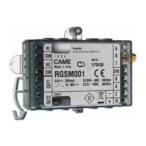
    Module pour la gestion à distance d’un ou de plusieurs automa- Toujours couper le courant électrique durant les opérations • tismes CAME, par le biais de CAMEConnect, doté de 2 entrées de nettoyage ou d'entretien. numériques, 2 sorties relais, 1 interface 485 et 1 carte GSM.
  • Page 21: Voyants De Signalisation Led

    7 Fiche antenne. Module alimenté et configuré/associé, 8 Antenne. Module non configuré (condition d’usine), I Carte RSE, à insérer sur les armoires de commande Came. Bouton P1 enfoncé. ❺ LED CONN (rouge) Voyants de signalisation LED Module connecté à CAMEConnect, Légende symboles voyants...
  • Page 22: Données Techniques

    Alimentation DC (V) 12 - 35 opération de connexion. Consommation (mA) Si le dispositif n’est pas alimenté par une armoire Came, Puissance signal radio s’assurer que l’alimentation fournie est bien dotée de disposi- 869,5MHz (dBm) tifs de protection contre tout courant dépassant 1 A.
  • Page 23 (*) Le tableau de compatibilité du module est disponible à La consommation des données dépend du nombre et du type  http://www.cameconnect.net/came/ l’adresse suivante : de dispositifs associés au module et de leur utilisation avec le docs/cameconnect_compliant_devices.html système CAMEConnect.
  • Page 24 Par exemple : APN:web.omnitel.it de l’APN, répéter la procédure de configuration de l’APN. Les opérateurs téléphoniques publient généralement cette in- Le module (RGSM001 - RGSM001S) doit être enregistré sur  formation sur leur site Internet ; si nécessaire, la demander à...
  • Page 25: Guide De Résolution Des Problèmes

    Guide de résolution des problèmes Le produit est conforme aux directives de référence en vigueur. Mise au rebut et élimination. Ne pas jeter l'emballage et le Causes Problème Solutions dispositif dans la nature au terme du cycle de vie de ce dernier, possibles mais les éliminer selon les normes en vigueur dans le pays où...
  • Page 26: Общие Правила Безопасности

    Это изделие должно использоваться исключительно по Модуль дистанционного управления одной или несколькими • назначению. Любое другое применение рассматривается как автоматическими системами CAME (макс. 3) посредством опасное. CAMEConnect, оснащенный 2 цифровыми входами, 2 релейны- Фирма-изготовитель снимает с себя всякую ответствен- ми выходами, интерфейсом 485 и платой GSM.
  • Page 27: Основные Компоненты

    Модуль обесточен 7 Разъем антенны. Модуль под напряжением и настроен/присвоен 8 Антенна. Модуль не настроен (заводские настройки) I Плата RSE, встраиваемая в блоки управления CAME. Нажата кнопка P1 ❺ Индикатор CONN (красный) Светодиодные индикаторы Модуль подключен к CAMEConnect Условные обозначения индикаторов...
  • Page 28: Технические Характеристики

    Перед выполнением подключений необходимо ОБЯЗА- Потребляемый ток (мА) ТЕЛЬНО ОТКЛЮЧИТЬ СЕТЕВОЕ ЭЛЕКТРОПИТАНИЕ. Мощность радиосигнала Если питание на устройство подается не с панели Came, 869,5 МГц (дБм) убедитесь в том, что линия подачи питания оснащена защитой для токов выше 1 A.
  • Page 29 скорости COM] в инструкции по эксплуатации автоматической В случае подключения к блоку управления CAME, осна- системы или блока управления). щенному CRP, через контакты A-B-GND, подавайте напряже- ние на модуль только через контакты 2-10 на самом блоке (*) С таблицей совместимости модуля можно ознакомить- Подключение...
  • Page 30 дать строчные, прописные буквы и знаки препинания). Если для замены SIM-карты требуется изменение APN,  повторите процедуру настройки APN. Например: APN:web.omnitel.it Необходимо зарегистрировать модуль (RGSM001 -  Как правило, телефонные операторы публикуют эту информа- RGSM001S) в своем личном кабинете на CAMEConnect, исполь-...
  • Page 31 облачному тарифным планом. чением материала. серверу. Проверьте настройки КОМПАНИЯ CAME S.P.A. СОХРАНЯЕТ ЗА СОБОЙ ПРАВО НА ИЗМЕ- APN с помощью опера- НЕНИЕ СОДЕРЖАЩЕЙСЯ В ЭТОЙ ИНСТРУКЦИИ ИНФОРМАЦИИ В ЛЮБОЕ ВРЕМЯ И БЕЗ ПРЕДВАРИТЕЛЬНОГО УВЕДОМЛЕНИЯ. ВСЕ тора мобильной связи. РАЗМЕРЫ ПРИВЕДЕНЫ В ММ, ЕСЛИ НЕ УКАЗАНО ИНОЕ.
  • Page 32 CAME S.p.A. Via Martiri Della Libertà, 15 31030 Dosson di Casier - Treviso - Italy tel. (+39) 0422 4940 - fax. (+39) 0422 4941...

Ce manuel est également adapté pour:

Rgsm001s

Table des Matières