Publicité
Les langues disponibles
Les langues disponibles
Liens rapides
Centrale elettronica
Electronic control unit
Centrale électronique
Elektronische Steuereinheit
Central electrónica
Central electrónica
Electrische zekering
900CT-101
MANUALE ISTRUZIONI
IT
INSTRUCTION MANUAL
GB
F
MANUEL D'EMPLOI
D
BEDIENUNGSANLEITUNG
E
MANUAL DE INSTRUCCIONES
MANUAL DE INSTRUÇÕES
P
PL
GEBRUIKSHANDLEIDING
NL
Key Automation
kering
S.p.A
Publicité

Manuels Connexes pour Key Automation 900CT-101


Sommaire des Matières pour Key Automation 900CT-101
- Page 1 Centrale elettronica Electronic control unit Centrale électronique Elektronische Steuereinheit Central electrónica Central electrónica Electrische zekering kering 900CT-101 MANUALE ISTRUZIONI INSTRUCTION MANUAL MANUEL D'EMPLOI BEDIENUNGSANLEITUNG MANUAL DE INSTRUCCIONES MANUAL DE INSTRUÇÕES GEBRUIKSHANDLEIDING Key Automation S.p.A...
- Page 2 JP4 MOTOR (N.19/20/21) in modo da invertire l’apre con il chiude. ATTENZIONE I dati e le informazioni indicate in questo manuale sono da ritenersi suscettibili di modi ca in qualsi- asi momento e senza obbligo di preavviso da parte di Key Automation S.r.l.
- Page 3 MODELLI E CARATTERISTICHE 900CT-101 con predisposizione per scheda radio. La centrale di comando 900CT-101 è destinata al comando di un motore asincrono monofase uti- lizzato per automatizzare il movimento di uno scorrevole o di un basculante. Ogni altro uso è improprio e vietato.
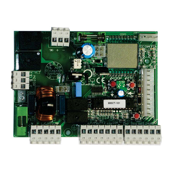
- Page 4 CONNETTORE CN1 Morsettiera collegamenti alimentazione 230Vac, lampeggiante e luce di cortesia 1) N Neutro 230Vac 2) F Fase 230Vac 3) L.C. Collegamento luce di cortesia max.25W 230Vac 4) COM LC/LP Comune luce cortesia e lampeggiante ( in LC tempo sso 2 min ) 5) LMP Collegamento lampeggiante max.25W 230Vac Per la sostituzione della lampada del lampeggiante o la lampada di cortesia togliere l’alimentazione...
- Page 5 CONNETTORE CN3 Morsettiera collegamento alimentazioni accessori 24Vac, secondo canale radio e antenna Uscita 2° canale radio (solo se si utilizza ricevitore innesto 2 canali) Uscita 2° canale radio (solo se si utilizza ricevitore innesto 2 canali) Collegamento antenna (segnale) Collegamento antenna (calza di schermatura) Alimentazione accessori 24Vac Max 10 Watt Alimentazione accessori 24Vac Max 10 Watt 1 2 3 4 5...
- Page 6 DIAGNOSI VISIVA La centrale di comando è stata progettata per automatizzare aperture residenziali ed industriali ad 1 motore con potenza massima di 1200W con controlli di sicurezza attivi e passivi per ottenere una installazione conforme alle vigenti normative di sicurezza. La grande af dabilità...
- Page 7 PROGRAMMAZIONE Si accede al menu dei parametri mantenendo premuto il pulsante ENTER (P2) nch appare il primo parametro, premendo consecutivamente il pulsante ENTER (P2) si avanza con il menù para- metri, per la variazione del parametro premere il pulsante UP/DO N (P1) N.B.
- Page 8 CONNETTORE RADIO La centrale CT-101 è compatibile con i seguenti ricevitori Key Automation della serie MEMO ad innesto: 900RXI-22 / 900RXI-42 / 900RXI-42R AVVERTENZE FINALI L’installazione dell’automazione deve essere eseguita a regola d’arte da personale quali cato...
- Page 9 NOTE ANMERKUNGEN NOTES NOTA NOTES OBSERVAÇÕES...
- Page 10 WARNING: It is advisable to read the instructions carefully before you start installation. Failure to comply with these instructions, improper use or incorrect connection may compromise the safety or correct operation of the device and hence of the entire system. No liability shall be accepted for any malfunctions and/or damage due to failure to comply with the instructions.
- Page 11 MODELS AND CHARACTERISTICS 900CT-101 Control unit for 1 230 Vac motor sliding or overhead motor, set up for radio card. TECHNICAL DATA CT-101 POWER SUPPLY 230Vac/50Hz MAX. MOTOR LOAD 1200 W ACCESSORIES POWER SUPPLY OUTPUT 24Vac 400mA WORKING TIME 0-120sec...
- Page 12 dedicated to the connection of the power supply of the board: 1) N 230Vac 2) F 230Vac 3) L.C. Courtesy light max.25W 230Vac 4) COM LC/LP Shared courtesy light or asher 5) LMP Connected to the asher max.25W 230Vac 1 2 3 4 5 6 7 8 9 10 11 12 13 14 15 16 17 18 230Vac RG58...
- Page 13 Accessory power supply connection 24Vac 15 watts max 2nd radio channel connection (only if using 2-channel radio connector) 2nd radio channel connection (only if using 2-channel radio connector) Antenna connection (signal) Antenna connection (mesh) 24Vac Max 10 Watt 24Vac Max 10 Watt 1 2 3 4 5 6 7 8 9 10 11 12 13 14 15 16 17 18 JP3 1)
- Page 14 VISUAL DIAGNOSIS The control unit is designed to automate residential and industrial openings with 1 motor having a maximum power of 1200W with active and passive safety controls for installation that is compliant with current safety standards. The great reliability of the system and the high concentration of the functions are managed by a micro-controller so that the system can autonomously calculate all deceleration parameters and the wor ing time with no special programming by the installer.
- Page 15 PROGRAMMING FUNCTIONS Access the parameter menu by holding the ENTER button until the rst parameter, appears. Press the ENTER button (P2) repeatedly to advance through the parameters menu. To change the pa- rameter press UP/DOWN (P1) N.B. any variation in function must be made with the automation closed FUNCTIONS/VALUES Medium Obstacle detection activated with L=0 and...
- Page 16 Provide a maintenance schedule for the system (at least every 6 months for the safeties) with an appropriate register of wor performed. Keep this instruction manual for future reference. Key Automation S.r.l. reserves the right to ma e, at any time, any modi cations which may be required to improve appearance and/or operation. DISPOSAL This product is composed of various components which may in turn contain pollutants.
- Page 17 NOTE ANMERKUNGEN NOTES NOTA NOTES OBSERVAÇÕES...
- Page 18 ATTENTION : Lire attentivement les instructions avant de proc der à l’installation. Le non-respect des instructions susmentionn es, toute utilisation impropre ou toute erreur de branchement peut nuire à la s curit ou au bon fonctionnement du disposi- tif et, par cons quent, à toute l’installation. Nous d clinons toute responsabilit en cas de mauvais fonctionnement et/ou de dommages d rivant du non-respect des instructions.
- Page 19 MODÈLES ET CARACTÉRISTIQUES 900CT-101 Centrale de commande pour 1 moteur 230 Vac pour portail coulissant ou basculant, prédisposition pour carte radio CARACTÉRISTIQUES TECHNIQUES CT-101 ALIMENTATION 230Vac/50Hz PUISSANCE MAX. MOTEUR 1200 W SORTIE ALIMENTATION AUXILIAIRES 24Vac 400mA DURÉE MOUVEMENT 0-120sec DURÉE PAUSE 0-120sec TEMPÉRATURE DE FONCTIONNEMENT...
- Page 20 Destiné à la connexion des alimentations de la carte 1) N 230Vac 2) F 230Vac 3) L.C. Relié à la lumière de courtoisie max.25W 230Vac 4) COM LC/LP Commun à la lumière de courtoisie ou à la lampe clignotante 5) LMP Relié...
- Page 21 Connexion 2e canal radio (seulement si l’on utilise un récepteur embrochable 2 canaux) Connexion 2e canal radio (seulement si l’on utilise un récepteur embrochable 2 canaux) Branchement antenne Branchement antenne 24Vac Max 10 Watt 24Vac Max 10 Watt 1 2 3 4 5 6 7 8 9 10 11 12 13 14 15 16 17 18 JP3 1) Condensateur...
- Page 22 DIAGNOSTIC VISUEL La centrale de commande a été conçue pour automatiser l’ouverture de portails résidentiels et industriels, avec 1 moteur puissance maximale 1200W. avec contrôles de sécurité actifs et passifs pour répondre aux normes de sécurité en vigueur. La grande abilité du système et la haute concentration des fonctions gérées par un microcontrô- leur permettent au système de calculer de façon autonome tous les paramètres de ralentissement et la durée de mouvement sans que l’installateur doive programmer quoi que ce soit.
- Page 23 FONCTIONS DE PROGRAMMATION Pour acc der au menu des param tres, maintenir la touche ENTER enfonc e jusqu’à ce que le premier param tre, le param tre, apparaisse ; appuyer plusieurs fois de suite sur la touche ENTER (P2) pour se d placer dans le menu des param tres ; pour modi er un param tre, appuyer sur la touche UP/DOWN (P1) N.B.
- Page 24 Conserver le présent manuel pour pouvoir le consulter par la suite. La société Key Automation S.r.l. se réserve le droit d’apporter, à tout moment, les modi cations qui s’avèreront nécessaires pour l’amélioration des caractéristiques esthétiques et/ou fonction- nelles de ses produits.
- Page 25 NOTE ANMERKUNGEN NOTES NOTA NOTES OBSERVAÇÕES...
- Page 26 ACHTUNG: Bevor Sie mit der Installation beginnen, lesen Sie die Bedienungsanleitung aufmerk- sam durch. Die Nichtbeachtung der oben aufgeführten Anweisungen, unsachgemäßer Gebrauch oder Anschlussfehler können die Sicherheit bzw. den einwandfreien Betrieb des Ge- räts und folglich der gesamten Anlage beeinträchtigen. Für Betriebsstörungen und/oder Schäden, die aus der Nichtbeachtung der Anwei- sungen entstehen, wird keinerlei Haftung übernommen.
- Page 27 MODELLE UND MERKMALE 900CT-101 Steuereinheit für 1 Motor 230Vac für Motor Schiebe- oder Schwenktore, Vorrüstung für Funkplatine TECHNISCHE DATEN CT-101 SPEISUNG 230Vac/50Hz MAX MOTORLAST 1200 W VERSORGUNGSAUSGANG ZUBEHÖR 24Vac 400mA ARBEITSZEIT 0-120sec PAUSENZEIT 0-120sec BETRIEBSTEMPERATUR -20°C/+70°C BESCHREIBUNG 25 26 27...
- Page 28 Ist für den Versorgungsanschluss der Platine bestimmt 1) N 230Vac 2) F 230Vac 3) L.C. Anschluss des Begrü ungslichts max.25W 230Vac 4) COM LC/LP normales Begrü ungslicht oder Blin licht 5) LMP Anschluss des Blin lichts max.25W 230Vac 1 2 3 4 5 6 7 8 9 10 11 12 13 14 15 16 17 18 230Vac RG58...
- Page 29 Anschluss 2. Fun anal (nur wenn Stec empf nger 2 Kan le benutzt wird) Anschluss 2. Fun anal (nur wenn Stec empf nger 2 Kan le benutzt wird) Anschluss Antenne (Signal) Anschluss Antenne (Um echtung) Anschluss Speisung Zubehör 24Vac 10 Watt zwischen Klemme Anschluss Speisung Zubehör 24Vac 10 Watt zwischen Klemme 1 2 3 4 5 6 7 8 9 10 11 12 13 14 15 16 17 18...
- Page 30 SICHTDIAGNOSE Die Steuereinheit wurde für die automatische Öffnung von Toren in Wohn- und Industriegeb uden mit 1 Motor mit maximaler Leistung von e 1.200 W mit a tiven und passiven Sicherheits ontrollen entwic elt, um eine Installation zu erhalten, die den geltenden Sicherheitsvorschriften entspricht. Durch die gro e Zuverl ssig eit des Systems und die hohe Konzentration der Fun tionen, die von einem Mi rocontroller gesteuert werden, ann das System alle Verlangsamungsparameter und die Arbeitszeit autonom berechnen, ohne besondere Programmierung durch den Installateur.
- Page 31 PROGRAMMIERFUNKTIONEN Man gelangt zum Parametermenü, indem man die Taste ENTER gedrückt hält, bis der erste Pa- rameter erscheint. Wenn man die Taste ENTER (P2) erneut drückt, geht man im Parametermenü weiter. Für die Änderung des Parameters die Taste UP/DOWN (P1) drücken Hinweis: Jede Änderung der Funktion muss bei geschlossenem Antrieb ausgeführt werden.
- Page 32 Versorgungsspannung gedrosselt wird, indem der Wert mit dem Parameter L geregelt wird. HINWEIS: für die maximalen Lasten des Anlaufstroms siehe geltende Bestimmungen. FUNKVERBINDER Das Steuerger t CT-101S ist mit den folgenden Empf ngern von Key Automation der Baureihe MEMO mit Stec verbinder ompatibel: 900RXI-22 / 900RXI-42 / 900RXI-42R ABSCHLIESSENDE HINWEISE...
- Page 33 NOTE ANMERKUNGEN NOTES NOTA NOTES OBSERVAÇÕES...
- Page 34 ATENCIÓN: Es conveniente leer las instrucciones antes de efectuar la instalación. El incumplimiento de las instrucciones, el uso incorrecto o un error de conexión po- drían comprometer la seguridad o el correcto funcionamiento del dispositivo, y por lo tanto de toda la instalación. Se declina cualquier responsabilidad por mal funcionamiento y/o daños derivados del incumplimiento de las instrucciones.
- Page 35 MODELOS Y CARACTERÍSTICAS 900CT-101 Central de control para 1 motor de 230V cd para motor corredero o basculante, prepa- rada para tar eta de radio DATOS TÉCNICOS CT-101 ALIMENTACIÓN 230Vac/50Hz CARGA MÁX MOTOR 1200 W SALIDA DE ALIMENTACIÓN DE ACCESORIOS...
- Page 36 Est dedicada a la conexión de las alimentaciones de la tar eta 1) N 230Vac 2) F 230Vac 3) L.C. Se conecta la luz de cortesía max.25W 230Vac 4) COM LC/LP Común de luz de cortesía o intermitente 5) LMP Se conecta el intermitente max.25W 230Vac 1 2 3 4 5 6 7 8 9 10 11 12 13 14 15 16 17 18...
- Page 37 Conexión 2º canal de radio (solo si se utiliza receptor de acoplamiento de 2 canales) Conexión 2º canal de radio (solo si se utiliza receptor de acoplamiento de 2 canales) Conexión de la antena (señal) Conexión de la antena (malla) Conexión de alimentación de accesorios 24Vac Max 10 Watt Conexión de alimentación de accesorios 24Vac Max 10 Watt 1 2 3 4 5...
- Page 38 DIAGNÓSTICO VISUAL La central de control ha sido diseñada para automatizar aperturas residenciales e industriales de 1 motor con potencia máxima de 1200W, con controles de seguridad activos y pasivos, para lograr una instalación conforme a las normativas de seguridad vigentes. La grande af dabilità...
- Page 39 FUNCIONES DE PROGRAMACIÓN Al menú de los parámetros se accede manteniendo pulsado el botón ENTER hasta que aparece el primer parámetro si se vuelve a pulsar el botón ENTER (P2) se avanza por el menú de paráme- tros. Para modi car el parámetro pulse el botón UP/DOWN (P1) Nota: toda modi cación de funcionamiento debe efectuarse con el automatismo cerrado FUNCIONES / VALORES...
- Page 40 Conserve el presente manual de instrucciones para futuras consultas. La empresa Key Automation S.r.l. se reserva la facultad indiscutible de aportar, en cualquier mo- mento, las modi caciones que se hiciesen necesarias a efectos de una me ora estética y/o funcio- nal.
- Page 41 NOTE ANMERKUNGEN NOTES NOTA NOTES OBSERVAÇÕES...
- Page 42 ATENÇÃO: oportuno ler com aten o as instru es antes de executar a instala A falta de observa o das instru es acima, o uso impróprio ou um erro de liga poderá prejudicar a seguran a ou o funcionamento correcto do dispositivo e, portan- to, de toda a instala Eximimo-nos de qualquer responsabilidade por eventuais maus funcionamentos e/ ou danos decorrentes da falta de observa...
- Page 43 MODELOS E CARACTERÍSTICAS 900CT-101 Central de comando para 1 motor 230Vac para motor corrediço ou basculante, predi- sposição para placa de rádio DADOS TÉCNICOS CT-101 ALIMENTAÇÃO 230Vac/50Hz CARGA MAX MOTOR 1200 W SAÍDA DE ALIMENTAÇÃO ACESSÓRIOS 24Vac 400mA TEMPO DE TRABALHO...
- Page 44 Dedicado à ligação das alimentações da placa 1) N 230Vac 2) F 230Vac 3) L.C. Ligada a luz de cortesia max.25W 230Vac 4) COM LC/LP Comum luz cortesia ou lampe ante 5) LMP Ligado o lampe ante max.25W 230Vac 1 2 3 4 5 6 7 8 9 10 11 12 13 14 15 16 17 18 230Vac RG58...
- Page 45 Ligação 2° canal rádio (somente se for utilizado o receptor engate 2canais) Ligação 2° canal rádio (somente se for utilizado o receptor engate 2canais) Ligação da antena (sinal) Ligação da antena (malha) Ligação da alimentação dos acessórios 24Vac Max 10 Watt Ligação da alimentação dos acessórios 24Vac Max 10 Watt 1 2 3 4 5 6 7 8 9 10 11 12 13 14 15 16 17 18...
- Page 46 DIAGNÓSTICO VISUAL A central de comando foi pro ectada para automatizar as aberturas residenciais e industriais com 1 motor com potência máxima de 1200W com controlos de segurança activos e passivos para obter uma instalação conforme às normas vigentes de segurança. La grande af dabilità...
- Page 47 FUNÇÕES DE PROGRAMAÇÃO Acede-se ao menu dos par metros mantendo carregado o bot o ENTER at aparecer o primeiro par metro, carregando seguidamente o bot o ENTER (P2) se avan a com o menu par metros, para a varia o do par metro carregar o bot o UP/DOWN (P1) N.B.
- Page 48 L N.B. para as cargas de propuls o máxima consultar as normas vigentes. CONECTOR RÁDIO A central CT-101 é compatível com os seguintes receptores Key Automation da série MEMO de encaixe: 900RXI-22 / 900RXI-42 / 900RXI-42R AVISOS FINAIS A instalação da automação deve ser executada segundo as regras da arte por pessoal quali ca-...
- Page 49 NOTE ANMERKUNGEN NOTES NOTA NOTES OBSERVAÇÕES...
- Page 50 O TRZE ENIE: E E E E E E E E E E E E : : : : : : : : : : : Zaleca si uwa ne przeczytanie instrukcji przed rozpocz ciem instalacji. Nieprzestrzeganie niniejszych instrukcji, niew a ciwe u ytkowanie lub niepoprawne pod czenie mo e mie negatywny wp yw na bezpiecze stwo lub poprawne dzia anie urz dzenia, a wi c i ca ego systemu.
- Page 51 MODELE I CHARAKTERYSTYKA 900CT-101 Jednost a steru ca dla silni a przesuwnego lub silni a napowietrznego 1 230 Vac z ustawie- niami dla arty radiowe . DANE TECHNICZNE CT-101 ZASILANIE 230Vac/50Hz MAX. OBCI ENIE SILNIKA 1200 W WYJ CIE ZASILANIA AKCESORIÓW...
- Page 52 Po wi cony pod czeniu zasilania do tablicz i: 1) N 230Vac 2) F 230Vac 3) L.C. O wietlenie dodat owe ma s.25W 230Vac 4) COM LC/LP Wspólne o wietlenie dodat owe lub lampa miga ca 5) LMP Pod czony do lampy miga ce ma s.25W 230Vac 1 2 3 4 5 6 7 8 9 10 11 12 13 14 15 16 17 18 230Vac...
- Page 53 Pod czenie zasilania a cesoriów ma s. 24Vac 15W Pod czenie drugiego ana u radia (tyl o w razie orzystania z czni a radia dwu ana owego) Pod czenie drugiego ana u radia (tyl o w razie orzystania z czni a radia dwu ana owego) Pod czenie anteny (sygna ) Pod czenie anteny (mesh) 24Vac ma s.10 Watt...
- Page 54 DIAGNOSTYKA WIZUALNA Ta ednost a steru ca zosta a zapro e towana dla bram rezydenc alnych oraz przemys owych z 1 sil- ni iem o ma symalne mocy 12000W oraz a tywnymi i pasywnymi ontrolami bezpiecze stwa i w celu instalac i zgodne z obowi zu cymi standardami bezpiecze stwa.
- Page 55 PROGRAMOWANIE FUNKCJI Wejd w menu parametru przytrzymuj c przycisk ENTER a do pojawienia si pierwszego parametru A. Naciskaj wielokrotnie przycisk ENTER, aby przewija menu parametrów. Aby zmieni parametr, naci nij przycisk UP/DOWN N.B. N.B.: wszelkie zmiany w funkcjach musz by wykonane przy zamkni tej bramie. FUNKCJE/WARTO CI red- rednia...
- Page 56 Zachowa ninie sze instru c e obs ugi na przysz o . Key Automation S.r.l. rezerwu e sobie prawo do wprowadzania w dowolnym momencie zmian niezb d- nych do ulepszania wygl du i/lub dzia ania produ tu.
- Page 57 NOTE ANMERKUNGEN NOTES NOTA NOTES OBSERVAÇÕES...
- Page 58 WAARSCHUWING: Het is aangeraden de instructies voorzichtig te lezen voor je de installatie begint. Mislukking om aan deze instructies of ongepast gebruik te voldoen of verkeerde aansluiting kan een compromis sluiten voor de veiligheid de operatie van het apparaat verslechteren en daarom van het volledige systeem. Geen aansprakelijkheid zal voor defecten aangenomen worden en/of beschadig ten gevolge van mislukking om aan de instructies te voldoen.
- Page 59 MODELLEN EN KENMERKEN 900CT-101 controle-eenheid voor 1 230 Vac motor die of overhead motor, bereid voor voor radio- aart. TECHNISCHE GEGEVENS CT-101 DRIJF AANBOD AAN 230Vac/50Hz MAX. MOTOR LADING 1200 W ONDERDELEN AANDRIJVING OUTPUT 24Vac 400mA WERKING TIJD 0-120sec PAUZEER TIJD...
- Page 60 Toegewi d naar de aansluiting van de netvoeding van de ze erings ast: 1) N 230Vac 2) F 230Vac 3) L.C. veiligheids licht max.25W 230Vac 4) COM LC/LP Gedeeld veiligheidslicht of asher 5) LMP Aangesloten aan asher max.25W 230Vac de 1 2 3 4 5 6 7 8 9 10 11 12 13 14 15 16 17 18...
- Page 61 Toebehorend netvoedingsaansluiting 24Vac 15 wattmax. 2de radio anaalaansluiting (en el indien 2- anaalradio oppelstu word gebrui t) 2de radio anaalaansluiting (en el indien 2- anaalradio oppelstu word gebrui t) Antenne aansluiting (sein) Antenne aansluiting (net) 24Vac Max. 10 Watts 24Vac Max. 10 Watts 1 2 3 4 5 6 7 8 9 10 11 12 13 14 15 16 17 18...
- Page 62 VISUELE DIAGNOSE De controle-eenheid wordt ontworpen residentiele en industriële openingen met 1 motor te auto- matiseren die een maximale macht van 1200W met actieve en passieve veiligheidscontroles voor installatie heeft die in schi ing met huidige veiligheidsstandaarden is. De geweldige betrouwbaarheid van het systeem en de hoge concentratie van de functies wordt door een micro-controleur geleid zodat het systeem autonoom alle vertragingsparameters en de wer ingsti d zonder speciale programmering van de installateur.
- Page 63 PROGRAMMEER FUNCTIES Verschaf toegang tot het parametermenu door het vasthouden van de ENTER knop tot de eerste parameter, verschijnt. Druk het Enter knop (P2) herhaaldelijk om door het parametermenu vooruit te gaan. Om de parameters te veranderen druk UP/DOWN (P1) N.B.
- Page 64 . Houd dit instructiehandboe voor toe omstige referentie bi . Key Automation S.r.l. Behoudt zich het recht, wanneer dan oo , wi zigingent te ma en die de ver- schi ning en/of operatie verbeteren.
- Page 65 NOTE ANMERKUNGEN NOTES NOTA NOTES OBSERVAÇÕES...
- Page 66 (In riferimento all’articolo 1519 bis ss. cc..) Key Automation congratulates with you for the excellent choice. We Key Automation si congratula con Lei per la scelta effettuata, al ne would li e to remind our customers that in order to obtain the maxi- di avere una durata massima dell’impianto Le ricordiamo di utilizzare...
- Page 67 Direttive Europee. Key Automation S.r.l. guarantees such a conformity only if the control unit is used as a control/management unit for automation system in typical con guration of installation and with peripherals which conform to the European Directives...
- Page 68 Key Automation S.r.l. P.IVA 03627650264 C.F. 03627650264 Via Alessandro Volta, 30 Capitale Sociale Euro 400.000,00 i.v. 30020 Noventa di Piave (Ve) Italia Reg. Imprese di Venezia n. 03627650264 T. +39 0421.307.456 REA VE326953 F. +39 0421.656.98 www.keyautomation.it info@keyautomation.it 580ISCT-101 rev09...