Key Automation 900CT-201 Manuel D'emploi
Masquer les pouces Voir aussi pour 900CT-201:
Table des Matières

Publicité

Les langues disponibles
  • FR

Les langues disponibles

  • FRANÇAIS, page 19

Liens rapides

Centrale elettronica
Electronic control unit
Centrale électronique
Elektronische Steuereinheit
Central electrónica
Central electrónica
900CT-201
IT
MANUALE ISTRUZIONI
GB
INSTRUCTION MANUAL
F
MANUEL D'EMPLOI
D
BEDIENUNGSANLEITUNG
E
MANUAL DE INSTRUCCIONES
P
MANUAL DE INSTRUÇÕES

Publicité

Table des Matières
loading

Sommaire des Matières pour Key Automation 900CT-201

  • Page 1 Centrale elettronica Electronic control unit Centrale électronique Elektronische Steuereinheit Central electrónica Central electrónica 900CT-201 MANUALE ISTRUZIONI INSTRUCTION MANUAL MANUEL D'EMPLOI BEDIENUNGSANLEITUNG MANUAL DE INSTRUCCIONES MANUAL DE INSTRUÇÕES...
  • Page 3: Table Des Matières

    INDICE SICUREZZA ...............................4 ATTREZZATURA...............................4 MODELLI E CARATTERISTICHE ........................5 QUADRO D’INSIEME / VERIFICHE PRELIMINARI ..................6 COLLEGAMENTI ELETTRICI ...........................7 PROGRAMMAZIONE ............................8 FUNZIONI DI PROGRAMMAZIONE........................9 CONNETTORE RADIO ............................10 SMALTIMENTO ...............................10 NOTE................................51 QUESTO LIBRETTO E’ DESTINATO SOLO ALL’INSTALLATORE L’installazione dovrà essere effettuata solamente da personale professionalmente qualificato in conformità a quanto previsto dalla legge vigente.
  • Page 4: Sicurezza

    SICUREZZA Ci congratuliamo con voi per l’ottima scelta affidataci. Questo manuale ha lo scopo di aiutarvi nell’installazione del vostro motoriduttore. Procedendo nella lettura troverete spiegazioni relative non soltanto alle funzioni del motoriduttore ma anche alle norme di sicurezza che dovrete garantire per avere sempre un perfetto funzionamento e la massima sicurezza.
  • Page 5: Modelli E Caratteristiche

    MODELLI E CARATTERISTICHE Centrale di comando per 1/2 motori 230Vdc, predisposizione per scheda radio, 900CT-201 fornita con box plastico DATI TECNICI CT-201 ALIMENTAZIONE 230Vac/50Hz CARICO MAX MOTORI 2X700W USCITA ALIMENTAZIONE ACCESSORI 24Vac 400mA TEMPO LAVORO 0-120sec TEMPO PAUSA 0-120sec TEMPERATURA DI FUNZIONAMENTO -20°C/+70°C...
  • Page 6: Quadro D'insieme / Verifiche Preliminari

    QUADRO D’INSIEME / VERIFICHE PRELIMINARI DESCRIZIONE Morsettiera collegamenti alimentazioni e terra CN1 Morsettiera collegamento motori /lampeggiante CN2 Morsettiera collegamento elettroserratura , finecorsa, comandi e sicurezze CN3+CN4 Morsettiera collegameto alimentazioni accessori 24Vac e secondo canale radio CN5 Display di segnalazione funzioni e ingressi di sicurezza Connettore per scheda radio ricevente ad innesto Connettore collegamento antenna Pulsante ENTER per lo scorrimento funzioni per la programmazione...
  • Page 7: Collegamenti Elettrici

    DIAGNOSI VISIVA La centrale di comando è stata progettata per automatizzare aperture ad 1/2 motori per automazione Battente con potenza massima di 700W cad. con controlli di sicurezza attivi e passivi per ottenere una installazione conforme alle vigenti normative di sicurezza. •...
  • Page 8: Programmazione

    Tale ingresso viene considerato una sicurezza, il contatto può essere interrotto in qualsiasi momento durante la chiusura dell’automazione provocando l’immediato blocco del moto invertendo il senso di marcia Funzione Fotocellula Open F2 : Collegata tra il Mors.N.21 ed il Mors.N.23 Contatto N.C. Normalmente Chiuso Tale ingresso viene considerato una sicurezza, il contatto può...
  • Page 9: Funzioni Di Programmazione

    FUNZIONI DI PROGRAMMAZIONE Si accede al menu dei parametri mantenendo premuto i pulsante ENTER finche appare il primo parametro A, premendo consecutivamente il pulsante ENTER si avanza con il menù parametri, per la variazione del parametro premere il pulsante ↕ UP/DOWN FUNZIONI \ VALORI TEMPO...
  • Page 10: Connettore Radio

    Conservare il presente manuale di istruzioni per future consultazioni. • La ditta KEY Automation Srl si riserva la facoltà insindacabile di apportare, in qualsiasi momento, le modifiche che si rendessero necessarie ai fini di un miglioramento estetico e/o funzionale. SMALTIMENTO Questo prodotto è...
  • Page 11 INDEX SAFETY................................12 EQUIPMENT ..............................12 MODELS AND CHARACTERISTICS ......................13 OVERALL VIEW / PRELIMINARY CHECKS ....................14 ELECTRICAL CONNECTIONS ........................15 PROGRAMMING..............................16 PROGRAMMING FUNCTIONS ........................17 RADIO CONNECTOR ............................18 DISPOSAL ...............................18 NOTES ................................51 THIS BOOKLET IS TO BE USED ONLY BY THE INSTALLER Installation must be carried out only by professionally qualified personnel in compliance with current legal requirements.
  • Page 12: Safety

    SAFETY Congratulations on your choice of our product. This manual will aid you in installing your reduction gear. As you read through it, you will find not only explanations on the operation of the reduction gear, but also on safety standards that you must comply with for perfect operation and maximum safety. To prevent damage to your unit and to avoid injury to yourself or others, before installing the reduction gear and its components, carefully read all of the following information on safety standards.
  • Page 13: Models And Characteristics

    MODELS AND CHARACTERISTICS Control unit for 1/2 motors, 230 V DC, set up for radio card, plastic box included 900CT-201 TECHNICAL DATA CT-201 POWER SUPPLY 230V AC/50Hz MAX. MOTOR LOAD 2X700W ACCESSORIES POWER SUPPLY OUTPUT 24V AC 400mA WORKING TIME...
  • Page 14: Overall View / Preliminary Checks

    OVERALL VIEW / PRELIMINARY CHECKS DESCRIPTION Terminal board for connections of power supply and earth CN1 Terminal board for connection of motors / flasher CN2 Terminal board for connection of electric lock, limit switch, controls and safeties CN3+CN4 Terminal board for connection of 24 V AC accessories power supply and second radio channel CN5 Display for signalling functions and safety inputs Connector for snap-in radio receiving card Antenna connector...
  • Page 15: Electrical Connections

    VISUAL DIAGNOSIS The control unit is designed to automate opening of 1/2 motors for hinged automation with maximum power of 700W ea. with active and passive safety controls for installation that is compliant with current safety standards. • The input STOP no. 22, which requires use of an NC contact, must be closed and the two points of the LCD must not flash.
  • Page 16: Programming

    This input is considered a safety, the contact can be interrupted at any time during opening by the automation causing an immediate stop in movement, the automation will continue until the contact is restored. Stop function STP : Connected to Term. N.22 and Term. N.23 Contact Normally Open N.C. This input is considered a safety the contact can be interrupted at any time immediately stopping the automation disabling any function including automatic closing.
  • Page 17: Programming Functions

    PROGRAMMING FUNCTIONS Access the parameter menu by holding the ENTER button until the first parameter, A, appears. Press the ENTER button repeatedly to advance through the parameters menu. To change the parameter press ↕ UP/DOWN FUNCTIONS \ VALUES WORKING TIME (seconds) DOOR2 DELAY...
  • Page 18: Radio Connector

    • Keep this instruction manual for future reference. • KEY Automation Srl reserves the right to make, at any time, any modifications which may be required to improve appearance and/or operation. DISPOSAL This product is composed of various components which may in turn contain pollutants. Do not dispose of it in the environment! Find out about the method for recycling or disposing of the product in compliance with current local laws.
  • Page 19 SOMMAIRE SÉCURITÉ................................20 OUTILS................................20 MODÈLES ET CARACTÉRISTIQUES ......................21 TABLEAU D'ENSEMBLE / CONTRÔLES PRÉLIMINAIRES.................22 BRANCHEMENTS ÉLECTRIQUES ........................23 PROGRAMMATION............................24 FONCTIONS DE PROGRAMMATION ......................25 CONNECTEUR RADIO............................26 MISE AU REBUT .............................26 NOTES ................................51 CE MANUEL EST EXCLUSIVEMENT DESTINÉ À L'INSTALLATEUR L'installation ne doit être effectuée que par des techniciens qualifiés et dans le respect des dispositions légales en vigueur.
  • Page 20: Sécurité

    SÉCURITÉ Nous vous remercions de votre choix et de la préférence accordée à nos produits. Ce manuel a été rédigé dans le but de vous aider lors de l'installation du motoréducteur. Ce manuel vous fournira non seulement des explications sur les fonctions du motoréducteur, mais aussi des informations sur les normes de sécurité...
  • Page 21: Modèles Et Caractéristiques

    MODÈLES ET CARACTÉRISTIQUES Centrale de commande pour 1/2 moteurs 230Vdc, prédisposition pour carte radio, 900CT-201 fournie avec boîtier en plastique CARACTÉRISTIQUES TECHNIQUES CT-201 ALIMENTATION 230 Vac / 50 Hz PUISSANCE MAX MOTEURS 2X700W SORTIE ALIMENTATION AUXILIAIRES 24 Vac 400 mA DURÉE MOUVEMENT...
  • Page 22: Tableau D'ensemble / Contrôles Préliminaires

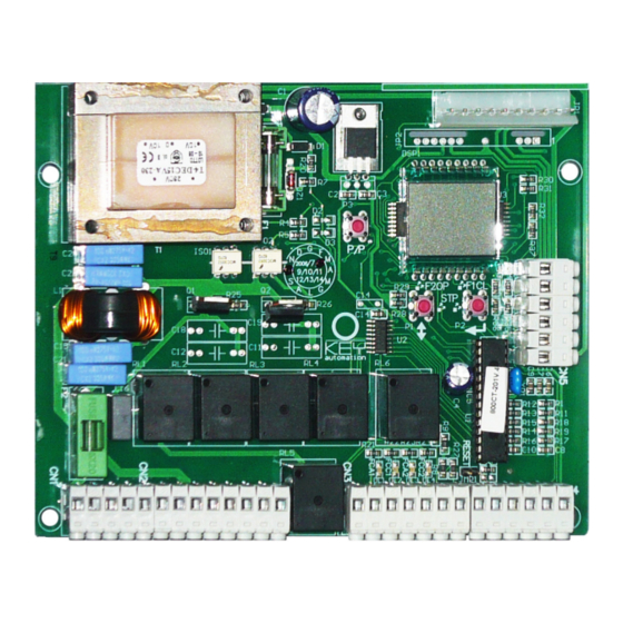
    TABLEAU D'ENSEMBLE / CONTRÔLES PRÉLIMINAIRES DESCRIPTION Bornier de connexion des alimentations et de mise à la terre CN1 Bornier de connexion des moteurs/feu clignotant CN2 Bornier de connexion serrure électrique, fin de course, commandes et dispositifs de sécurité CN3+CN4 Bornier de connexion aux alimentations des accessoires 24 Vac, en fonction du canal radio CN5 Afficheur de signalisation des fonctions et des entrées de sécurité...
  • Page 23: Diagnostic Visuel

    DIAGNOSTIC VISUEL La centrale de commande a été conçue pour automatiser les ouvertures à 1/2 moteurs pour automation Battant avec puissance maximale de 700W chacun avec contrôles de sécurité actifs et passifs pour répondre aux normes de sécurité en vigueur. •...
  • Page 24: Programmation

    Fonctionnement Pas-à-Pas P/P : Connecté entre la borne N° 19 et la borne N°23 Contact N.O. Normalement Ouvert Entrée de commande Ouvrir/Fermer ou Ouvrir/Stop/Fermer en fonction de la sélection du paramètre D Fonction Photocellule Close F1 : Connectée entre la borne N°20 et la borne N°23 Contact N.F. Normalement Fermé Cette entrée est considérée comme une sécurité, le contact peut être coupé...
  • Page 25: Fonctions De Programmation

    FONCTIONS DE PROGRAMMATION Pour accéder au menu des paramètres, maintenir la touche ENTER enfoncée jusqu'à ce que le premier paramètre A, apparaisse ; appuyer plusieurs fois de suite sur la touche ENTER pour se déplacer dans le menu des paramètres ; pour modifier un paramètre, appuyer sur la touche ↕ UP/DOWN FONCTIONS \ VALEURS TEMPS TRAVAIL...
  • Page 26: Réglage De La Force Des Moteurs

    Conserver le présent manuel pour pouvoir le consulter par la suite. • La société KEY Automation Srl se réserve le droit d'apporter, à tout moment, les modifications qui s'avèreront nécessaires pour l'amélioration des caractéristiques esthétiques et/ou fonctionnelles de ses produits.
  • Page 27 INHALTSVERZEICHNIS SICHERHEIT ..............................28 AUSRÜSTUNG ..............................28 MODELLE UND MERKMALE .........................29 GESAMTZEICHNUNG / VORABKONTROLLEN....................30 ELEKTRISCHE ANSCHLÜSSE ........................31 PROGRAMMIERUNG ............................32 PROGRAMMIERFUNKTIONEN ........................33 FUNKVERBINDER............................34 ENTSORGUNG ..............................34 ANMERKUNGEN .............................51 DIESES HANDBUCH IST NUR FÜR DEN INSTALLATEUR BESTIMMT Die Installation darf nur von qualifiziertem Fachpersonal gemäß der vom geltenden Gesetz vorgesehenen Bestimmungen ausgeführt werden.
  • Page 28: Sicherheit

    SICHERHEIT Wir beglückwünschen Sie zur Ihrer ausgezeichneten Wahl. Dieses Handbuch soll Ihnen bei der Installation Ihres Antriebs helfen. Im weiteren Verlauf wird nicht nur auf die Funktionen des Antriebs eingegangen, sondern auch auf die Sicherheitsbestimmungen, die für einen einwandfreien und absolut sicheren Betrieb unbedingt beachtet werden müssen.
  • Page 29: Modelle Und Merkmale

    MODELLE UND MERKMALE Steuereinheit für 1/2 Motoren 230Vdc, Vorrüstung für Funkplatine, mit 900CT-201 Plastikgehäuse geliefert TECHNISCHE DATEN CT-201 SPEISUNG 230Vac/50Hz MAX LAST DER MOTOREN 2X700W VERSORGUNGSAUSGANG ZUBEHÖR 24Vac 400mA ARBEITSZEIT 0-120 sec PAUSENZEIT 0-120 sec BETRIEBSTEMPERATUR -20°C/+70°C SCHUTZGRAD IP56 Bevor Sie mit der Installation beginnen, lesen Sie die Bedienungsanleitung aufmerksam durch.
  • Page 30: Gesamtzeichnung / Vorabkontrollen

    GESAMTZEICHNUNG / VORABKONTROLLEN BESCHREIBUNG Klemmenleiste Versorgung und Erdung CN1 Klemmenleiste Anschluss Motoren /Blinklicht CN2 Klemmenleiste Anschluss Elektroschloss, Endschalter, Steuerungen und Sicherheitsvorrichtungen CN3+CN4 Klemmleiste Anschluss Speisung Zubehör 24Vac und zweiter Funkkanal CN5 Display für die Anzeige der Funktionen und Sicherheitseingänge Verbinder für Funkempfangsplatine zum Einstecken Verbinder Antennenanschluss Taste ENTER für das Durchlaufen der Funktionen für die Programmierung Taste UP/DOWN für die Variation und Regelung der Funktionseinstellung (siehe Tabelle)
  • Page 31: Elektrische Anschlüsse

    SICHTDIAGNOSE Die Steuereinheit wurde für die Automatisierung von Öffnungen mit 1/2 Motoren für Drehflügel mit maximaler Leistung von je 700W mit aktiven und passiven Sicherheitskontrollen entwickelt, um eine Installation zu erhalten, die den geltenden Sicherheitsvorschriften entspricht. • Der Eingang STOP Nr. 22, an dem ein NC-Kontakt benutzt werden muss, muss geschlossen sein und die zwei Punkte des LCD dürfen NICHT blinken.
  • Page 32: Programmierung

    Angeschlossen zwischen Klemme Nr.19 und Klemme Nr.23 NO-Kontakt, normalerweise offen Befehlseingang Öffnen/Schließen oder Öffnen/Stop/Schließen, abhängig von der Auswahl des Parameters D Funktion Lichtschranke Close F1: Angeschlossen zwischen Klemme Nr.20 und Klemme Nr.23 NC-Kontakt, normalerweise geschlossen Dieser Eingang wird als Sicherheit angesehen, der Kontakt kann während der Schließung des Antriebs jederzeit unterbrochen werden und bewirkt die sofortige Unterbrechung der Bewegung und die Richtungsumkehr.
  • Page 33: Programmierfunktionen

    PROGRAMMIERFUNKTIONEN Man gelangt zum Parametermenü, indem man die Taste ENTER gedrückt hält, bis der erste Parameter A erscheint. Wenn man die Taste ENTER erneut drückt, geht man im Parametermenü weiter. Für die Änderung des Parameters die Taste ↕ UP/DOWN drücken. FUNKTIONEN \ WERTE ARBEITSZEIT (Sekunden)
  • Page 34: Funkverbinder

    Register alle durchgeführten Eingriffe eintragen. • Diese Gebrauchsanweisung zum späteren Nachschlagen sorgfältig aufbewahren. • Die Firma KEY Automation Srl behält sich das unanfechtbare Recht vor, Änderungen, die für eine ästhetische oder funktionelle Verbesserung als notwendig angesehen werden, in jedem beliebigen Moment durchzuführen. ENTSORGUNG Dieses Produkt setzt sich aus verschiedenen Bauteilen zusammen, die umweltbelastende Substanzen enthalten könnten.
  • Page 35 ÍNDICE SEGURIDAD ..............................36 EQUIPO................................36 MODELOS Y CARACTERÍSTICAS.........................37 CUADRO DE CONJUNTO / COMPROBACIONES PRELIMINARES............38 CONEXIONES ELÉCTRICAS..........................39 PROGRAMACIÓN ............................40 FUNCIONES DE PROGRAMACIÓN .......................41 CONECTOR DE RADIO...........................42 ELIMINACIÓN ..............................42 NOTA................................51 ESTE MANUAL ESTÁ DESTINADO SOLO AL INSTALADOR La instalación deberá ser realizada únicamente por personal profesionalmente cualificado según cuanto previsto por la legislación vigente.
  • Page 36: Seguridad

    SEGURIDAD Le felicitamos por haber confiado en nosotros. Este manual tiene como objetivo ayudarle en la instalación de su motorreductor. Leyéndolo, encontrará explicaciones relativas no sólo a las funciones del motorreductor sino también a las normas de seguridad que deben respetarse para garantizar siempre un funcionamiento perfecto con la máxima seguridad.
  • Page 37: Modelos Y Características

    MODELOS Y CARACTERÍSTICAS Central de control para 1/2 motores de 230V cd, preparada para tarjeta de radio, 900CT-201 suministrada con caja de plástico DATOS TÉCNICOS CT-201 ALIMENTACIÓN 230V ca/50Hz CARGA MÁX MOTORES 2X700W SALIDA DE ALIMENTACIÓN DE ACCESORIOS 24V ca 400mA TIEMPO DE FUNCIONAMIENTO 0-120 seg.
  • Page 38: Cuadro De Conjunto / Comprobaciones Preliminares

    CUADRO DE CONJUNTO / COMPROBACIONES PRELIMINARES DESCRIPCIÓN Bornera de conexiones de alimentación y a tierra CN1 Bornera de conexión de motores /intermitente CN2 Bornera de conexión de cerradura electrónica, fines de carrera, mandos y dispositivos de seguridad CN3+CN4 Bornera de conexión de alimentación de accesorios de 24V ca y segundo canal de radio CN5 Pantalla indicadora de funciones y entradas de seguridad Conector de acoplamiento para la tarjeta receptora de radio Conector de conexión de antena...
  • Page 39: Conexiones Eléctricas

    DIAGNÓSTICO VISUAL La central de control ha sido diseñada para la automatización de aperturas batientes con 1/2 motores con potencia máxima de 700W cada uno, con controles de seguridad activos y pasivos, para lograr una instalación conforme a las normativas de seguridad vigentes. •...
  • Page 40: Programación

    Función de la Fotocélula Close F1: conectada entre el borne nº 20 y el borne nº 23. Contacto N.C. Normalmente Cerrado Dicha entrada se considera un dispositivo de seguridad; el contacto puede interrumpirse en cualquier momento durante el cierre del automatismo, con lo que se provoca inmediatamente el bloqueo de la marcha y se invierte su sentido.
  • Page 41: Funciones De Programación

    FUNCIONES DE PROGRAMACIÓN Al menú de los parámetros se accede manteniendo pulsado el botón ENTER hasta que aparece el primer parámetro A. Si se vuelve a pulsar el botón ENTER se avanza por el menú de parámetros. Para modificar el parámetro pulse el botón ↕...
  • Page 42: Conector De Radio

    Conserve el presente manual de instrucciones para futuras consultas. • La empresa KEY Automation Srl se reserva la facultad indiscutible de aportar, en cualquier momento, las modificaciones que se hiciesen necesarias a efectos de una mejora estética y/o funcional. ELIMINACIÓN Este producto está...
  • Page 43 ÍNDICE SEGURANÇA..............................44 FERRAMENTAS ..............................44 MODELOS E CARACTERÍSTICAS.........................45 QUADRO DE CONJUNTO / VERIFICAÇÕES PRELIMINARES ..............46 LIGAÇÕES ELÉCTRICAS..........................47 PROGRAMAÇÃO ............................48 FUNÇÕES DE PROGRAMAÇÃO........................49 CONECTOR RÁDIO............................50 ELIMINAÇÃO ..............................50 OBSERVAÇÕES..............................51 ESTE MANUAL É DESTINADO SOMENTE PARA O INSTALADOR A instalação deverá ser efectuada somente por pessoal profissionalmente qualificado em conformidade com quanto previsto pela lei vigente.
  • Page 44: Segurança

    SEGURANÇA Nos congratulamos com V.Sas. pela óptima escolha que nos foi concedida. Este manual tem a finalidade de ajudá-los na instalação do vosso motorredutor. Com a leitura deste manual poderão ser encontradas explicações relativas às funções do motorredutor e também às normas de segurança que deverão ser observadas para ter sempre um perfeito funcionamento e a máxima segurança.
  • Page 45: Modelos E Características

    MODELOS E CARACTERÍSTICAS Central de comando para 1/2 motores 230Vdc, predisposição para placa de rádio, 900CT-201 fornecida com caixa plástica DADOS TÉCNICOS CT-201 ALIMENTAÇÃO 230Vac/50Hz CARGA MAX MOTORES 2X700W SAÍDA DE ALIMENTAÇÃO ACESSÓRIOS 24Vac 400mA TEMPO DE TRABALHO 0-120seg TEMPO DE PAUSA...
  • Page 46: Quadro De Conjunto / Verificações Preliminares

    QUADRO DE CONJUNTO / VERIFICAÇÕES PRELIMINARES DESCRIÇÃO Régua de bornes das ligações das alimentações e terra CN1 Régua de bornes da ligação dos motores /lampejante/fechadura CN2 Régua de bornes da ligação da fechadura eléctrica, fim de curso, comandos e seguranças CN3+CN4 Régua de bornes da ligação de alimentações dos acessórios 24Vac, segundo canal de rádio CN5 Ecrã...
  • Page 47: Ligações Eléctricas

    DIAGNÓSTICO VISUAL A central de comando foi projectada para automatizar aberturas com 1/2 motores para automação de Batente com potência máxima de 700W cad. com controlos de segurança activos e passivos para obter uma instalação conforme às normas vigentes de segurança. •...
  • Page 48: Programação

    Função Fotocélula Close F1 : Ligada entre o Borne N.20 e o Borne N.23 Contacto N.C.Normalmente Fechado Essa entrada é considerada uma segurança, o contacto pode ser interrompido a qualquer momento durante o fechamento da automação provocando o bloqueio imediato do movimento invertendo o sentido de marcha Função Fotocélula Open F2 : Ligada entre o Borne N.21 e o Borne N.23 Contacto N.C.
  • Page 49: Funções De Programação

    FUNÇÕES DE PROGRAMAÇÃO Acede-se ao menu dos parâmetros mantendo carregado o botão ENTER até aparecer o primeiro parâmetro A, carregando seguidamente o botão ENTER se avança com o menu parâmetros, para a variação do parâmetro carregar o botão ↕ UP/DOWN FUNÇÕES \ VALORES TEMPO FUNCIONAMENTO...
  • Page 50: Conector Rádio

    • Guarde este manual de instruções para consultas futuras. • A empresa KEY Automation Srl reserva-se o direito incontestável de efectuar, a qualquer momento, as alterações que forem necessárias para um melhoramento estético e/ou funcional. ELIMINAÇÃO Este produto é composto por vários componentes que, por sua vez, poderão conter substâncias que poluem.
  • Page 51: Anmerkungen

    NOTE ANMERKUNGEN NOTES NOTA NOTES OBSERVAÇÕES...
  • Page 52 MADE IN ECC...

Table des Matières