Publicité
Les langues disponibles
Les langues disponibles
Liens rapides
G e n e r a l i n f o r m a t i o n :
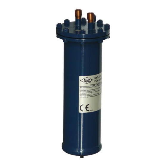
The function of oil separator is the separation of oil from hot gas of discharge line and
returning it back to the compressor or to the oil reservoir in systems with multiple
compressors.
S a f e t y i n s t r u c t i o n s :
• Read operating instructions thoroughly. Failure to comply can result in device
failure, system damage or personal injury.
• According to EN 13313 it is intended for use by persons having the appropriate
knowledge and skill.
• In a severely contaminated system, avoid breathing acid vapors and avoid
contact with skin from contaminated refrigerant / lubricants. Failure to do so
could result in injury.
• Before opening any system make sure pressure in system is brought to and
remains at atmospheric pressure.
• Do not release any refrigerant into the atmosphere!
• Do not exceed the specified maximum ratings for pressure and temperature.
• Do not use any other fluid media without prior approval of EMERSON. Use
of fluids not listed could result in:
- Change of hazard category of product and consequently change of
conformity assessment requirement for product in accordance with
European pressure equipment directive 2014/68/EU.
• Ensure that design, installation and operation are according to European and
national standards/regulations.
• The oil separator must be used only for the purpose it is designed for.
M o u n t i n g l o c a t i o n :
The oil separator should be installed as close as possible to the compressor(s) in the
main discharge line (Fig.1 & 2) but after any installed muffler or vibration adsorber.
(1)
Oil separator
(2)
Oil return line to compressor
crankcase or to oil reservoir
(3)
Compressor
(4)
Condenser
• Warning: Prevent the migration of liquid refrigerant back into the oil
separator shell during off-cycles by one of the following recommendations:
- Install the oil separator in a location where it is higher than condenser.
- If the oil separator located slightly lower than condenser, install the line from oil
separator to the condenser at higher level than the condenser and with a
downward slope into the condenser inlet connection.
- In systems which the condenser located higher than the oil separator, it is
recommended the use of a check valve at outlet of oil separator.
I n s t a l l a t i o n :
• Before proceeding with the installation, the oil separator must be charged with
certain amount of oil in order to actuate the float mechanism immediately after
start-up. Use the same type of oil as filled in the compressor crankcase.
• 0.5 Liter initial oil charge for OSH/OST-4xx
• 0.6 Liter initial oil charge for OSB/OSH-6xx
• The oil must be charged through outlet connection.
• The oil separator shell must be mounted securely in a vertical position.
• Warning: Protect the oil separator against vibration and gas pulsation
generated by compressor. Install the vibration adsorber and muffler between
compressor and oil separator.
• The oil return line (minimum 3/8" or 10 mm tube) should be connected to the
compressor crankcase or to the oil reservoir in the systems with multiple
compressors.
B r a z i n g :
• Perform and consider the brazing joint as per EN 14324.
• Before and after brazing clean tubing and brazing joints.
• Minimize vibrations in the piping lines by appropriate solutions.
• To avoid oxidization, it is advised to purge the system with an inert gas such as
nitrogen while brazing.
• When brazing, direct flame away from shell. Use wet rags or other suitable heat
protection to prevent damage to the paint surfaces adjacent the fittings.
• Do not exceed the max. body temperature of max. 150°C!
• Warning: The oil separators OSB/OST with flange cap are incorporated a
gasket. If so, the gasket can be destroyed, and it must be replaced. Keep the
flange cap cool.
Emerson Climate Technologies GmbH
Am Borsigturm 31 I 13507 Berlin I Germany
Operating instructions
Oil separators OSB / OSH / OST
(5)
Oil level controller
(6)
Connection line to suction line
(7)
Differential oil pressure switch
(8)
Oil reservoir
www.climate.emerson.com/en-gb
L e a k a g e T e s t :
After completion of installation, a pressure test must be carried out as follows:
- according to EN 378 for systems which must comply with European pressure
equipment directive 2014/68/EU.
- to maximum working pressure of system for other applications.
Warning:
• Failure to do so could result in loss of refrigerant and personal injury.
• The pressure test must be conducted by skilled persons with due respect
regarding the danger related to pressure.
• In case of detection of leakage around flange of oil separators OSB and OST, check
the gasket and the tightness of bolts with 35 Nm torque. A spare gasket is supplied
with each OSB and OST oil separator.
• After leakage test, the unused spare gasket should be taped or hanged in a position
near oil separator for use when it is required.
O p e r a t i o n :
• After leakage test, start system. The oil level in compressor crankcase and in oil
reservoir must be watched after start-up, the first hours of operation and few days
later. The new refrigerant will adsorb some oil. It may a small portion of oil to be
trapped in the system somewhere in lines or heat exchangers.
• The oil separator removes the excess oil but this may not be retained in compressor
crankcase immediately.
• In normal operation, the oil return line to the compressor crankcase or to the oil
reservoir which will be alternatively hot and cold. This is caused by opening and
closing of the needle valve via lifting and lowering of the float mechanism.
• In outdoor installation at low ambient temperatures, the oil separator may be needed
to be protected against cold stream of air in order to prevent the condensation of
refrigerant in the oil separator shell. The condensed liquid refrigerant will be sent
through oil return line into the compressor crankcase, creating foam in the oil and
causing lubrication problem. Oil separators perform best when operating at or near
the compressor discharge temperature. It is advisable to insulate the oil separator
shell.
• Warning: During operation of system, the shells have a high surface
temperature.
S e r v i c e / M a i n t e n a n c e :
• Oil separator OSB and OST are equipped with flange and can be opened for
cleaning. Always use a new gasket (Gasket set – Part No. 808800) and tight the bolts
with 35 Nm torque.
• The external surface of shells is coated by epoxy powder painting for optimum
protection against corrosion. The external surface of shell shall be checked as per
EN-378 during routine/periodic inspection/service.
T e c h n i c a l D a t a :
Maximum working pressure PS
Temperature range TS
Date code on label
Initial required Oil Charge (liter)
Volume (liter)
Hazard Category/ Conformity Assessment
(PED 2014/68/EU)
Refrigerants
OSH-4.../OSH-6../OST-4.../OSB-6...
OSH-4.../OST-4.../
Note: Fluid group classification
according to PED 2014/68/EU.
Dimensions
Markings
OS_OI_EN_DE_FR_ES_IT_RU_0420_R08_862958.docx
31 bar
-10...+150°C
Mxxxx (Made in Mexico)
OSH-4.. / OST-4...:
0.5
OSB-6.. / OST-6...:
0.6
OSH-4.. / OST-4...:
1.8 ... 3.8
OSB-6.. / OST-6...:
6.5 ... 7.9
Cat. II / Modul D1
Fluid group II (A1):
R134a, R404A, R407C, R410A,
R448A, R449A, R450A, R452A,
R507, R513A
Fluid group I (A2L)
R32, R444B, R447A, R452B,
R454B, R454A, R454C, R455A,
R1234ze, R1234yf
See Fig. 3
0036
(
only A1 refrigerants)
Date: 30.04.2020
Publicité

Manuels Connexes pour Emerson Alco Controls OSB


Sommaire des Matières pour Emerson Alco Controls OSB
- Page 1 • After leakage test, start system. The oil level in compressor crankcase and in oil • Do not use any other fluid media without prior approval of EMERSON. Use reservoir must be watched after start-up, the first hours of operation and few days of fluids not listed could result in: later.
- Page 2 B e s c h r e i b u n g : Nach der Installation ist ein Drucktest durchzuführen: Ölabscheider von EMERSON sorgen dafür, dass Öl aus dem Heißgas abgetrennt - gemäß EN 378 für Geräte, die die Europäische Druckgeräterichtlinie 2014/68/EU und zum Verdichter, bei Verbundanlagen zum Ölsammelgefäß, zurückgeführt wird.
- Page 3 F o n c t i o n n e m e n t : • Ne pas utiliser un autre fluide que ceux indiqués sans l’approbation obligatoire d’EMERSON. L'utilisation d'un fluide non approuvé peut conduire à: • Après le test d'étanchéité, mettre en route. Le niveau d'huile dans le carter - Le changement de la catégorie de risque d'un produit et par conséquent le...
- Page 4 • No use ningún fluido que no haya sido previamente aprobado por fuera necesario. EMERSON. El uso de sustancias no aprobadas puede dar lugar a: O p e r a c i ó n : - un cambio en la categoría de riesgo del producto y, en consecuencia, de los •...
- Page 5 OSB e OST è necessario controllare la guarnizione ed il tiraggio dei bulloni • Non utilizzare altri fluidi senza la previa approvazione di EMERSON. L’uso applicando un momento di serraggio pari a 35 Nm. Con ogni separatore d’olio del di refrigeranti non indicati nelle specifiche potrebbe causare: tipo OSB e OST viene fornita una guarnizione di ricambio.
- Page 6 перегрева (мокрая ветошь, теплоотводящая паста). Маркировка • Не превышайте максимальную температуру корпуса 150°C! (Только хладагент А1) • Warning: Маслоотделители OSB/OST с фланцевой крышкой имеют Emerson Climate Technologies GmbH www.climate.emerson.com/en-gb Date: 30.04.2020 Am Borsigturm 31 I 13507 Berlin I Germany OS_OI_EN_DE_FR_ES_IT_RU_0420_R08_862958.docx...
- Page 7 OST-404 881860 1/2“ OST-405 881861 5/8“ OST-407 881862 7/8“ OST-409 881863 1-1/8“ OST-411 881938 1-3/8“ OST-413 881939 1-5/8“ OSB-613 881971 1-5/8“ OSB-617 881972 2-1/8“ Emerson Climate Technologies GmbH www.climate.emerson.com/en-gb Date: 30.04.2020 Am Borsigturm 31 I 13507 Berlin I Germany OS_OI_EN_DE_FR_ES_IT_RU_0420_R08_862958.docx...