Xylem Sensus MeiStreamRF Manuel D'installation
Compteur d'eau industriel jusqu'à 50 degrés c avec redresseur de flux (mid)
Les langues disponibles
Les langues disponibles
EN DE FR ES
IT
PL
MeiStreamRF / MeiStreamRF Plus
MB 9202
MeiStream / MeiStreamPlus
Installation Manual
1.
Product description:
Bulk meter for water up to 50 °C
2.
Applications
MeiStream/MeiStream Plus/MeiStreamRF/MeiStreamRF Plus 50 °C / PN 16 or 40
- Measurement of cold potable water up to 50 °C
- Measurement of clean water up to 50 °C
3.
Included in the delivery
1 Water meter; 2 Gaskets; 1 Manual
Technical data
Refer to the technical data sheets LB 1010, LB 1020, LB 1060 and LB 1080 (http://www.sensus.com)
Installation instructions
5.1
Safety tips
5.1.1
No mechanical stresses may be exerted on the meter when installed in the pipeline. The pipeline flanges must align
with the meter flanges and the distance between the flanges must match the meter body length. Mis-alignment stresses
can cause the meter body or flanges to crack. When the pipeline is under pressure this can cause flooding.
5.1.2
The meter must not be subjected to pressures higher than the pressure rating printed on the meter. Too high pressure
can cause leaks or burst the meter body.
5.2
General instructions
5.2.1
The
meter
must
be
installed
by
a
trained
and
instructed
standards of good practice have to be respected (We refer to the instructions given in ISO 4064-5:2014).
After the manufacturing process all meters are disinfected. The meters must be stored in a dry, cool, dust and germs
5.2.2
free environment. Prior installation the meter must be disinfected again. Make sure that during the installation
procedure all hygienic standards and recommendations are respected.
5.3
Installation Tools
Two spanners for the corresponding size of bolts used are necessary. Hoisting devices may be required, depending on
the weight of the meter and the installation conditions.
5.4
Installation instructions
5.4.1
The meter with flow stabilizer does not need any straight upstream or downstream pipe (U0D0).
5.4.2
The maximum medium temperature shall not exceed 50 °C when in operation and 70 °C at down-time.
5.4.3
The environmental temperature must be within 5 and 70 °C.
5.4.4
The meters are classified acc. to 2014/32/EU (MID) in the mechanical environment class M2 (significant or high levels
of vibration and shock) and in the electromagnetic environment class E2.
The pipe diameter should not be abruptly reduced or expanded directly upstream or downstream the meter. All
5.4.5
diameter changes should be done with an angle <8° related to the pipe centre.
5.4.6
All flow regulating devices (e.g. Valves, PRV's) shall be installed downstream of the meter.
5.4.7
When selecting the installation site, consider the meter orientation (horizontal/vertical)!
5.4.8
Gaskets must not protrude into the pipeline or be mis-aligned.
5.4.9
The pipeline must be thoroughly flushed before installing the meter to prevent damage from debris.
5.4.10
The flow direction of the meter (arrow on the meter body) must correspond with the flow direction in the pipeline.
5.4.11
After installation of the meter, the pipeline must be filled with water very slowly to prevent the meter being damaged
by surges. Filling the pipe too rapidly can cause air / water surges which can destroy the meter insert.
5.4.12
The installation site should be selected to prevent air bubbles collecting in the meter and the pipeline must always be
completely filled with water. Installation of a meter at the highest point in a pipeline must be avoided. Eventually a
suitable air release device must be installed upstream the meter.
5.4.13
The manufacturer's Q
value must not be exceeded for extended periods.
3
5.4.14
The meter should be protected from stones, sand and fibrous material with a suitable strainer or filter.
5.4.15
The meter must be protected from pressure surges.
5.4.16
During operation always an upstream pressure of 0.3 bar must be ensured.
Exchanging the measuring insert
5.4.17
•
Metrological units must be replaced by metrological units with an identical metrology marking. Metrological
units with MID approval must be installed only in bodies with the marking "MID" on the upper flange surface.
•
Before the installation of a replacement measuring insert the inside surface of the body, especially the sealing areas of
the O-ring must be checked for damage. A new O-ring must be used. Prior installation of the new metrological unit the
meter body must be cleaned and disinfected.
•
The O-ring and the lip seal must be lubricated with grease approved for use with potable water before installation into
the meter body.
•
To avoid damaging the O-ring when installing a meter insert, the O-ring must first be fitted onto the cover flange and
then pushed into the meter body. If the O-ring is fitted into the body first, it can be pinched when fitting the meter insert
and cause leaks.
•
When installing the measuring insert into the meter body make sure that the direction of the arrow on the head flange
aligns with the arrow on the meter body.
•
The screws fixing the measuring insert in the body shall be screwed hand tight and then tightened crosswise with an
Allen key. The recommended torque is 40 Nm (M12) or 160 Nm (M16). Using the composite head flange the torque
shall not exceed
20 Nm.
•
With meters used for billing at least one screw of the measuring insert shall be sealed against the meter body after the
exchange to avoid tampering.
6.
Reading
The black digits on the roller counter indicate whole cubic metres. Parts of a cubic metre are indicated by the red sweep
hands. If there is a factor "x10" printed under the roller counter it requires the reading to be multiplied by 10 for a reading to
the nearest 10 cubic meters. For a reading to the nearest cubic metre, the black sweep hand must be read. Please see display
example below: The complete volume is 13,572m³.
with flow stabilizer (MID)
Mechanical register display
MeiStream / MeiStream Plus
DN 40 ... 125
worker.
Thereby
the
recognised
DN 150 ... 300
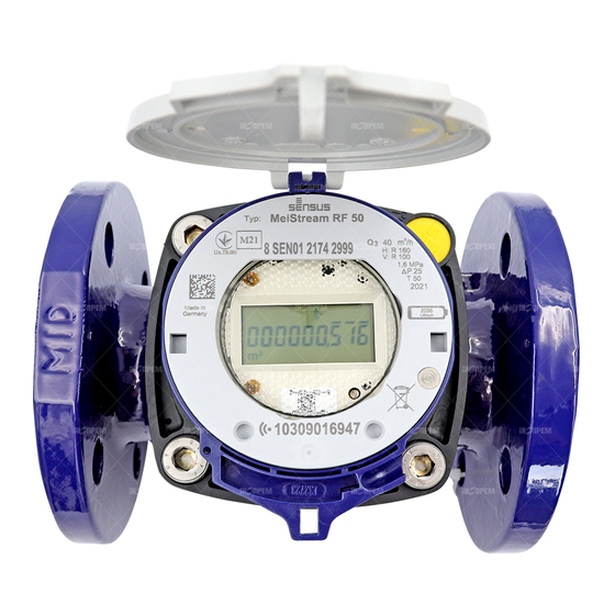
Electronic register display MeiStreamRF / MeiStreamRF Plus
Cubic Meters
Electronic register display
MeiStreamRF / MeiStreamRF Plus
LCD Segments test
(1 sec every minute)
Testing Mode
Forward Flow
Reverse Flow
Alarm Set
Firmware Version*/ Check Sum*
(1 sec every minute)
*variable
Flow Direction
LC Display
Forward Flow
+ with flashing circle
Reverse Flow
- with flashing circle
No Flow
Neither +, nor - circle
Transmission icon
Flashing mode by activated radio (1 sec on/ 1 sec off)
Low Battery Types
Description
Low battery alarm will be triggered 15
Low Battery
months before the calculated end of life.
(steady display – not blinking)
Low battery alarm will be triggered 6 months
Very Low Battery
before the calculated end of life (flashing
display)
The "Bell" icon is flashing when the register is in a testing mode
When an alarm is triggered the alarm icon will be visible on the LCD
Litre
Imperial Gallons
US Gallons
Cubic Feet
7. Orientation
Type
Register *)
MeiStream
MeiStreamRF
Upwards or 90°
slanted
MeiStream Plus
MeiStreamRF Plus
Upwards
*) when used for billing the marking on the type plate must be followed
9. Maintenance and cleaning
Under normal conditions the meter is maintenance free. If required the measuring insert can be
removed and cleaned (when used for billing national regulations must be followed). Chemicals,
sharp objects or high-pressure cleaners must not be used for cleaning. Respect section 5.2.2 of this
instruction.
10. Disposal
This product contains a lithium Ion battery. In the interest of protecting the environment, this
battery may not be disposed in household waste after its period of use. The local and national
regulations for environmental protection are to be considered.
1241
Lithium
Kilo Litre
8. Transport
Pipe *)
Horizontal
Vertical
Horizontal
Table des Matières

Manuels Connexes pour Xylem Sensus MeiStreamRF


Sommaire des Matières pour Xylem Sensus MeiStreamRF
-
Page 3: Données Techniques
EN DE FR ES Lecture 7. Orientacion 8. Transport MeiStreamRF / MeiStreamRF Plus MB 9202 Les chiffres noirs des rouleaux indiquent les m3 et leurs multiples. Les sous-multiples sont indiqués par les pointeurs rouges. Pour les compteurs de calibre supérieur ou égal au DN150, l’indication fournie par les rouleaux doit être multipliée par 10 (x10 Type Totalisateur *) Conduite *)