Publicité
Les langues disponibles
Les langues disponibles
Liens rapides
Franklin Electric Co., Inc.
P. O. Box 12010
Oklahoma City, OK 73157-2010
405.947.2511 • Fax: 405.947.8720
www.LittleGiantPump.com
CustomerService-WTS@fele.com
English • Français • Español:
Deutsch • Italiano • Nederlands • Svenska:
INTRODUCTION
EN
Your Little Giant Electronic Condensate Unit is designed as an automatic
condensate removal system for the water dripping off an air conditioner
evaporative coil up to 10KW. The pump is controlled by a float/switch device
which turns the pump on when approximately 1/2 inch (14mm) of water collects
in the water collection reservoir, and automatically switches off when the water
collection reservoir drains to approximately 3/8 inch (9,8mm).
This instruction sheet provides you with the information required to safely own
and operate your Little Giant pump. The unit you have purchased is a small but
powerful drain pump for the positive displacement of condensate from fan coils
and air conditioners. The design of this unit allows the air handlers to be located
away from the water drains since the condensate can be pumped to a common
drain a distance away.
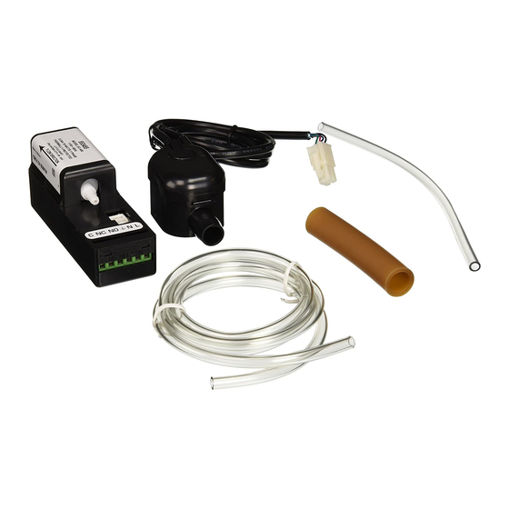
The EC-400 has been uniquely designed to be used to remove condensation
from high, wall mount, split-system air conditioning equipment. It can be installed
internally or externally in any system due to its 2-piece design. The Electronic
Condensate Unit consists of two parts - the water collection reservoir and control
unit/pump. The water collector reservoir is positioned near the bottom of the
air handler. The control unit/pump can be affixed internal or external to the air
handler according to the suction lift of the pump.
READ THESE INSTRUCTIONS CAREFULLY BEFORE ATTEMPTING TO
INSTALL, OPERATE, OR SERVICE YOUR LITTLE GIANT PUMP. KNOW
THE PUMP'S APPLICATION, LIMITATIONS, AND POTENTIAL HAZARDS.
PROTECT YOURSELF AND OTHERS BY OBSERVING ALL SAFETY
INFORMATION. FAILURE TO COMPLY WITH THESE INSTRUCTIONS COULD
RESULT IN PERSONAL INJURY AND/OR PROPERTY DAMAGE! RETAIN
THESE INSTRUCTIONS FOR FUTURE REFERENCE.
SAFETY GUIDELINES
SHUT OFF ELECTRICAL POWER AT FUSE BOX BEFORE ATTEMPTING TO
SERVICE, DISCONNECT CONNECTOR OR REMOVE ANY COMPONENT!
Do not use to pump flammable or explosive fluids such as gasoline, fuel oil,
kerosene, etc. Do not use in explosive atmospheres.
Do not handle pump with wet hands or when standing on a wet or damp surface
or in water.
In any installation where property damage and/or personal injury might result
from an inoperative or leaking pump due to power outages, discharge line
blockage, or any reason, a backup system(s) and/or alarm should be used.
Support pump and piping when assembling and when installed. Failure to do so
may cause piping to break, pump to fail, motor bearing failures, etc.
Place control unit/pump in an area where there is no danger of ingress of water.
INSTALLATION
1. Installation of the Collection Reservoir:
Locate the water collecting reservoir in a suitable position below the bottom
level of the drip tray of the air conditioner. Air conditioners are not always
correctly cleaned in the factory during manufacture. Because packaging debris
(styrofoam, cardboard, etc.) may penetrate inside, it is recommended to rinse the
air conditioner drip pan with water before connecting the reservoir unit.
Be certain that the bottom of the reservoir is within (+/-) 15 degrees of being level
with the optimum performance being when the reservoir is level.
If the reservoir is not mounted properly, the float mechanism may not function
properly and may cause the unit to overflow.
Attach the 1/2 inch (13mm) tubing (item 1) to the reservoir intake and the drip tray
drain. Be certain to support the reservoir when attaching tubing and that tubing is
not kinked when reservoir is in place. The reservoir can be located inside the air
handler. Connect the 5/32 inch (4mm) tubing (item 3) to the outlet of the reservoir
marked "VENT". The free end of the tubing must be secured above the highest
level of the drip tray in the air conditioner to prevent overflow. Be certain that the
tubing is not kinked when installed.
2. Installation of the Control Unit/Pump:
The pump can be mounted internal or external to the air handler (according to
ELECTRONIC CONDENSATE UNIT
ÉVACUATEUR ÉLECTRONIQUE DE
CONDENSAT
UNIDAD ELECTRÓNICA DE
CONDENSACIÓN
MODEL • MODÈLE • MODELO
EC-400 230V
C
1 - 6
C
7 - 12
the suction lift of the pump) using the Ty-Rap provided. Connect the 5/32 inch
(4mm) tubing (item 5) to the intake of the pump (indicated by the direction of flow
arrow on the side of pump) and to the outlet on the reservoir marked "PUMP"
using the hose clamps provided (item 4). Be certain the tubing is not kinked when
pump is installed.
The suction lift of the pump is a maximum of 3 feet (1 meter).
Run a length of 5/32 (4mm) tubing (not provided) from the discharge of the pump
using a hose clamp (item 4) to a drain.
NOTE: Be sure the end of the discharge hose is not lower than 3 ft. (1 meter)
below the reservoir. Also, be sure the pump is not located next to insulation or
flammable material.
Be certain that there are no sharp bends or kinks in the suction and discharge
hoses. Keep all hoses and cables clear of moving parts in the air handler.
ELECTRICAL CONNECTIONS
SHUT OFF ELECTRICAL POWER AT FUSE BOX BEFORE MAKING ANY
CONNECTIONS. ALL WIRING MUST COMPLY WITH LOCAL CODES. CHECK
THE CONTROL UNIT LABEL FOR PROPER VOLTAGE REQUIRED. DO NOT
CONNECT TO VOLTAGE OTHER THAN THAT SHOWN.
Connect the cable from the reservoir tank to the control unit/pump by inserting
the 4-prong plug connector into the corresponding socket on the control unit/
pump.
To attach a power cable from the 230V power supply of the air handler to
the terminal block of the control unit/pump, remove the screw cover (item 6)
exposing the screws. Place the correct lead into the corresponding slot of the
terminal block. Tighten the screw that corresponds with the appropriate terminal
block slot.
POWER SUPPLY TO CONTROL UNIT: blue (neutral) to N, brown (line) to L,
green/yellow to ground
.
A 0.2 amp fuse should be fitted in the power cable supplying the control unit.
The unit is equipped with a high water alarm. Connect the cables as follows to
obtain the desired response: C and NC - When water rises, circuit opens to turn
off the compressor and prevents overflow. C and NO - When water rises, circuit
closes to activate a bell or alarm (not provided). After all connections are made,
snap the screw cover (item 6) into slot above screws on terminal block.
SERVICE INSTRUCTIONS
MAKE CERTAIN THAT THE UNIT IS DISCONNECTED FROM THE POWER
SOURCE
BEFORE
ATTEMPTING
COMPONENTS.
Inspect and clean the reservoir tank when air conditioner is serviced or at the
beginning of the season.
Reservoir: Carefully remove the reservoir cover being careful not to damage the
O-ring. Remove the mesh screen and rinse under running water. Use a damp rag
to remove dust or debris from the reservoir. Be certain that the beveled edge of
the float is up when reassembling the reservoir.
There are no user serviceable parts inside pump. Warranty is limited to
replacement only and will be void if pump is tampered with. Any repair on pump
must be done by an authorized Little Giant service center.
INTRODUCTION
FR
Votre appareil électronique de condensation Little Giant est conçu comme un
système d'évacuation automatique de la condensation de l'eau qui s'égoutte de
la bobine d'évaporation d'un conditionneur-diffuseur pouvant atteindre 10 kW. La
pompe est commandée par un interrupteur à flotteur. Celui-ci actionne la pompe
lorsque le niveau d'eau dans le réservoir de récupération atteint environ 14 mm
(1/2 po), et l'éteint une fois le niveau ramené à près de 9,8 mm (3/8 po).
La présente feuille d'instructions contient les renseignements nécessaires à une
utilisation sécuritaire de l'évacuateur électronique de condensat Little Giant. Votre
nouvel appareil consiste en une pompe d'épuisement, petite mais puissante, qui
évacue le condensat provenant des serpentins de ventilateurs et de climatiseurs.
La pompe permet de placer les appareils de traitement d'air loin des dispositifs
de purge d'eau, vu la possibilité de pomper le condensat à un drain commun,
situé plus loin.
Le EC-400 a été conçu pour évacuer le condensat des climatiseurs muraux à
deux blocs. Il peut être installé à l'intérieur ou à l'extérieur de l'appareil, dans le
réservoir de récupération, la pompe et l'unité de contrôle. L'appareil électronique
de condensation est constitué de deux parties : le réservoir de collecte d'eau
et le boîtier de commande/pompe. La pompe peut être apposée (à l'intérieur
ou l'extérieur) à ce même appareil en fonction de la hauteur d'aspiration de la
pompe. Le boîtier de commande/pompe peut être fixé à l'intérieur ou à l'extérieur
de l'armoire de traitement d'air selon la hauteur d'aspiration de la pompe.
BIEN LIRE LES INSTRUCTIONS AVANT D'INSTALLER, DE FAIRE
FONCTIONNER OU D'ENTRETENIR LA POMPE LITTLE GIANT. IL FAUT
1
TO
SERVICE
OR
REMOVE
ANY
Publicité

Manuels Connexes pour Franklin Electric Little Giant EC-400 230V


Sommaire des Matières pour Franklin Electric Little Giant EC-400 230V
- Page 1 “PUMP” CONDENSAT using the hose clamps provided (item 4). Be certain the tubing is not kinked when Franklin Electric Co., Inc. UNIDAD ELECTRÓNICA DE pump is installed.
- Page 2 6. SCREW COVER * 7.CONTROL UNIT/PUMP CAPUCHONS DES VIS BOÎTIER DECOMMANDE/POMPE 4. HOSECLAMP * TAPA DE LOS TORNILLOS UNIDAD/BOMBA DECONTROL 153780 COLLIER DE SERRAGE *REPLACEMENT PART NUMBER 153799 ABRAZADERA DE NUMÉRO DE LA PIÈCE DE RECHANGE 153799 RESERVOIR CABLE NÚMERO DE COMPONENTE DE RECAMBIO 153799 FIL POUR LE RÉSERVOIR 4.
- Page 3 chiffon humide pour enlever la poussière et les débris du réservoir. Au moment del nivel más alto de la cubeta de goteo en el aire acondicionado, para prevenir el du réassemblage,s’assurer que l’extrémité biseautée du flotteur est placée vers le rebosamiento.
- Page 4 LIMITED WARRANTY GARANTIE LIMITÉE Your product is guaranteed to be in perfect condition when it leaves our Factory. Votre produit est garanti pour être dans la condition parfaite quand il quitte notre It is warranted against defective materials and workmanship for a period of 12 Usine.
- Page 5 GARANTIA LIMITADA El producto está garantizado a estar en perfectas condiciones al momento de salir de la fábrica. El producto está garantizado contra materiales y fabricación defectuosa por un período de 12 meses desde la fecha en la cual fue comprada por el usuario.
- Page 6 TROUBLESHOOTING INFORMATION • INFORMATION SUR LA RELÈVE DES DÉRANGEMENTS • INFORMACION DE INVESTIGACION DE AVERIAS PROBLEM •FONCTIONNEMENT PROBABLE CAUSES • CAUSES DÉFECTEUX • PROBLEMA PROBABLES • CAUSAS PROBABLES CORRECTIVE ACTION • SOLUTIONS • SOLUCION Check incoming voltage to control unit • Vérifier la tension d’arrivée à l’unité de Voltage is not getting to pump •...
- Page 7 Luftaufbereitungseinheit oder extern montiert werden. MODEL • MODELL Das 5/32 Zoll (4 mm) - Schlauch (Teil 5) mit dem Einlass der Pumpe (durch die Franklin Electric Co., Inc. EC-400 Richtung des Strömungspfeils an der Seite der Pumpe angezeigt) und mit dem P.
- Page 8 6. Schraubenabdeckung* 7. Steuereinheit/pumpe Coperchio viti 4. Schlauchklemme* Schroefdeksel Unità di controllo/pompa Fascetta stringitubi Skruvskydd Bedieningseenheid/pomp *Ersatzteil - Nr. 153799 Slangklem Styrenhet/pump 153780 Numero pezzo da sostituire 153799 Tankkabel Slangklämma Nummer van het vervangstuk 153799 Cavo serbatoio 4. Schlauchklemme* Reservdelsnummer 153799 Reservoirkabel Fascetta stringitubi Kabel, uppsamlingskärl...
- Page 9 Controllare e pulire il serbatoio quando si effettua la manutenzione del 2. Installatie van de bedieningseenheid/pomp: condizionatore o all’inizio della stagione. De pomp kan, volgens de zuighoogte van de pomp, intern of extern aan de Serbatoio: Rimuovere con cautela il coperchio del serbatoio avendo cura di non luchtverwerker worden bevestigd met de bijgeleverde Ty-Rap.
- Page 10 är placerat nära botten på luftberedningssystemet. Styrenheten/pumpen kan Pumpens sughöjd är max 1 meter (3 fot). monteras internt eller externt i förhållande till luftberedningssystemet, beroende Dra en 4 mm (5/32) slang (ingår ej) från pumpens utlopp till ett avlopp och på...
- Page 11 Der “National Electric Code” (in den USA) und ähnliche Bestimmungen in anderen Ländern 2. Het produkt is aangesloten op een andere spanning dan vermeld op het naamplaatje. schreiben die Installation eines Erdschlufl-Schaltunterbrechers im Zweigstromkreis vor, der 3. Het snoer is korter dan 0,91 meter gemaakt. Brunnenbauteile mit einer Nennspanung von über 15 Volt mit Strom versorgt.
- Page 12 Deze drukverliezen zijn vastgesteld op basis van een slang met een 4 mm (5/32 inch) binnendiameter. Dessa tryckförluster har fastställts baserat på slang med innerdiametern 4 mm (5/32 tum). Form 998165 - 04/14/2009 © 2009 Franklin Electric Co., Inc. Little Giant® is a registered trademark of Franklin Electric Co., Inc.