Weller WQB 3000 Mode D'emploi
Table des Matières
Les langues disponibles
Les langues disponibles
Liens rapides
Chapitres
Table des Matières

Manuels Connexes pour Weller WQB 3000


Sommaire des Matières pour Weller WQB 3000
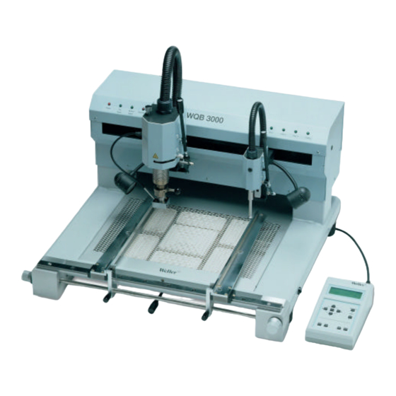
- Page 1 BGA / QFP-Rework System WQB 3000 Manuel d‘Utilisation Version 1.4...
-
Page 2: Table Des Matières
Table des matières Description Caractéristiques techniques Mise en service 2.1 Installation 2.2 Préparatifs 2.3 Fixation et positionnement de la carte imprimée et de la buse de soudage Utilisation avec l'unité de programmation 3.1 La courbe de température 3.2 Démarrage du processus de soudage 3.3 Déroulement du programme 3.4 Modification des paramètres de soudage 3.5 Mémorisation et chargement de programmes... -
Page 3: Description
Description Le système de réparation WQB 3000 est conçu pour effectuer des réparations de qualité aussi bien sur des composants BGA que sur des composants FINEPITCH. Le concept sophistiqué de l'appareil allie une grande fiabilité, une sécurité maximale du processus, une utilisation agréable et des solutions détaillées techniquement au point. -
Page 4: Caractéristiques Techniques
Caractéristiques techniques : Dimensions (L x l x h) env. 650 X 600X 500 mm Tension secteur 230V, 50/60Hz Fusible secteur T10A Puissance 2300W chauffage supérieur : 700 W chauffage inférieur : grand 1600W (260 X 260)mm petit 400W ( 120 X 120)mm Alim. -
Page 5: Fixation Et Positionnement De La Carte Imprimée Et De La Buse De Soudage
2.3 Fixation et positionnement de la carte imprimée et de la buse de soudage La table de travail est équipée d'un support de carte imprimée x – y à réglage de précision. Les bras du support (21) peuvent être déplacés après avoir desserré les vis de blocage (22). La carte à réparer peut alors être mise en place. -
Page 6: Démarrage Du Processus De Soudage
Réglage des paramètres STEP 1 – STEP 3 Température du chauffage inférieur 50°C - 400°C Température de la buse 50°C - 400°C Débit d'air (5 – 50l/min) 10% - 100% Temps 0sec. - 999sec. Réglages complémentaires Temps de refroidissement 0sec. - 999sec. -
Page 7: Déroulement Du Programme
Le processus de soudage est généralement activé en pressant la touche START alors que la buse à gaz chaud est soulevée. S T E P 1 P 0 1 Démarrage du programme - - - - - - - - - - - - - - - - - - - - Démarrage et exécution du →... -
Page 8: Modification Des Paramètres De Soudage
3.4 Modification des paramètres de soudage Les paramètres peuvent être modifiés temporairement pour adapter le processus de soudage à la carte à réparer. Cette fonction peut être exécutée uniquement lorsque l'unité de programmation n'est pas verrouillée. L'emplacement du programme mémorisé reste inchangé. L'unité... -
Page 9: Détermination De La Courbe De Température Avec Des Sondes Externes (Teach-In)
Sélection du menu : → touche SELECT : Sélectionner le programme avec les touches fléchées ∧ ∨ Charger : LOAD (P01-P30) (puis valider la sélection avec SELECT) SAVE AS → touche SELECT : Sélectionner le programme avec les touches fléchées ∧ ∨ Mémoriser : (P01-P30) (puis valider la sélection avec SELECT) →... -
Page 10: Teach-In Manuel
Attention : Les températures mesurées de la sonde Sensor1 sont déterminantes pour le déroulement du processus de Teach-In automatique. Les températures limites de la sonde 1 peuvent maintenant être modifiées avec les touches fléchées ∧ ∨ et confirmées avec la touche SELECT. A U T O M A T I C T E A C H - I N Mode Teach-In... -
Page 11: Fonctions Spéciales
Les différentes étapes du programme doivent être activées manuellement en pressant la touche START. Lorsque le temps de refroidissement est écoulé, il est nécessaire de mettre fin manuellement au processus en pressant la touche START ou la touche STOP. Les quatre temps déterminés se trouvent maintenant dans la mémoire temporaire de l'emplacement de programme. -
Page 12: Utilisation De La Tête De Soudage Et De La Tête De Placement
Les fonctions suivantes sont réglables : OFFSET NOZ. : Offset de température chauffage supérieur -50°C à +50°C OFFSET PREH. : Offset de température chauffage inférieur -50°C à +50°C STANDBY NOZ. : Température Stand-By chauffage supérieur OFF à +400°C STANDBY PREH. : Température Stand-By chauffage inférieur OFF à... -
Page 13: Placement Des Composants
(petits perçages). Activer ensuite l'aspiration sur la tête de placement. Lorsque la tête de placement descend, le composant est pris et peut être soulevé du gabarit métallique. Description des modules WQB 3000 6.1 Appareil de base • Robuste structure soudée rigide, en profilés de tôle d'acier •... -
Page 14: Tête De Placement
6.3 Tête de placement • Guidage linéaire de précision pour le déplacement dans l'axe Z, course env. 80 mm • Descente amortie de la tête de placement • Design intelligent, tous les câbles sont protégés et inapparents • Actionnement du préhenseur à aspiration par un bouton-poussoir à l'avant de la tête de placement •... -
Page 15: Fournitures
2 m de conduite pour air comprimé • Mode d'emploi • Logiciel de démonstration WQB 3000 Control pour l'utilisation de l'appareil avec un PC Accessoires (en option) • Grand choix de buses à gaz chaud et de gabarits de positionnement •... -
Page 16: Tableau Des Buses À Gaz Chaud
Tableau des buses à gaz chaud pour WQB 3000 Réf. Corps de buse intérieur Corps de buse extérieur mm x mm mm x mm 587 47 947 7.6 x 7.9 8.6 x 8.9 587 47 943 6.5 x 6.5 7.5 x 7.5 587 47 945 8.5 x 8.5... -
Page 17: Consignes De Sécurité
à proximité de l'appareil de soudage. Le non respect des avertissements peut être à l'origine d'accidents et de blessures ou de dommages pour la santé. Le système de réparation WELLER BGA WQB 3000 est conforme à la déclaration de conformité européenne en application des exigences fondamentales de sécurité de la directive 89/336/CEE, 73/23/CEE et 89/392/CEE. - Page 18 22. Faites réparer votre outil de soudage par un électricien qualifié. Cet outil de soudage est conforme aux consignes de sécurité en vigueur. Les réparations doivent être effectuées uniquement par un électricien qualifié, avec des pièces de rechange WELLER d'origine. Dans le cas contraire, l'utilisateur s'expose à un risque d'accident.
-
Page 19: Illustrations
Illustrations Sonde de température PT 100 Buse à gaz chaud Levier articulé tête de soudage Fermeture rapide tête de soudage Réglage thêta tête de soudage Ventilateur pour phase de refroidissement Levier articulé tête de placement Elément chauffant chauffage supérieur Bouton-poussoir aspiration tête de Prise pour sondes externes placement Tête de soudage... - Page 20 Raccord d'air comprimé 400 - 600 kPa Vis de blocage bras de serrage Interface RS 232 pour unité de Chauffage inférieur IR avec tôle de programmation ou PC recouvrement Module de connexion avec interrupteur Vis de réglage entraînement de précision secteur et porte-fusible (T 10A) support de carte imprimée direction x Unité...