
Manuels Connexes pour Fisher & Paykel OR30SDBMX


Sommaire des Matières pour Fisher & Paykel OR30SDBMX
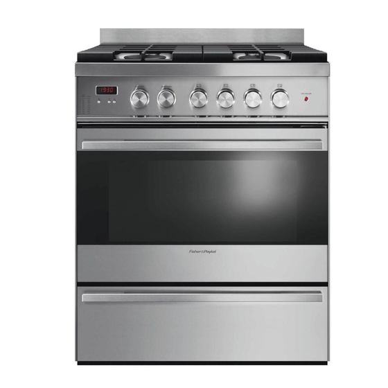
- Page 1 Freestanding range User guide OR30SDBMX model Cuiseur indépendant Guide d’utilisation OR30SDBMX model US CA...
-
Page 2: What To Do If You Smell Gas
WARNING ! To reduce the risk of tipping the appliance, the appliance must be secured by properly installed anti-tip device packed with the appliance. • ALL RANGES CAN TIP • INJURY TO PERSONS COULD RESULT • INSTALL ANTI-TIP DEVICE PACKED WITH RANGE •... - Page 3 GAS RANGE for residential use only USERS OPERATING INSTRUCTIONS IMPORTANT - PLEASE READ AND FOLLOW • Before beginning, please read these instructions completely and carefully. • Do not remove permanently affi xed labels, warnings, or plates from the product. This may void the warranty.
- Page 5 Dear Customer, Thank you for having purchased and given your preference to our product. The safety precautions and recommendations reported below are for your own safety and that of others. They will also provide a means by which to make full use of the features offered by your appliance. Please preserve this booklet carefully.
-
Page 6: General Information
USER INSTRUCTIONS GENERAL INFORMATION WARNING!! WARNING!! ELECTRICAL GROUNDING INSTRUCTIONS This appliance shall not be used for space heating. This The range must be electrically grounded in accordance with information is based on safety considerations. local codes or, in the absence of local codes, with the Natio- nal Electrical Code, ANSI/NFPA No. - Page 7 IMPORTANT PRECAUTIONS AND RECOMMENDATIONS After having unpacked the appliance, check to ensure that it is not damaged. In case of doubt, do not use it and consult your supplier or a professionally qualifi ed technician. Packing elements (i.e. plastic bags, polystyrene foam, nails, packing straps, etc.) should not be left around within easy reach of children, as these may cause serious injuries.
-
Page 8: Gas Burners
features Fig. 1.1 GAS BURNERS Rear left Semi-rapid burner (SR) - 8000 BTU/hr Rear right Semi-rapid burner (SR) - 8000 BTU/hr Front right Dual burner (D) - 17000 BTU/hr Front left Dual burner (D) - 17000 BTU/hr Note: • The electric gas-ignition device is incorporated into the dials. •... -
Page 9: Controls Description
Fig. 1.2 CONTROLS DESCRIPTION Gas cooking hob controls: Oven controls: Front left burner (4) control knob Oven light & fan function control knob Rear left burner (1) control knob Oven and broil burner temperature control knob Rear right burner (2) control knob Cooling fan failure warning light Front right burner (3) control knob Clock and timer... - Page 10 how to use the top burners GAS BURNERS (Semi-rapid) Gas fl ow to the burners is adjusted by turning the dials (illustrated in fi g. 2.1) which con- trol the valves. Turning the dial so that the symbols printed on the dial point to the mark on the bezel achieves the following functions: Dial Function...
- Page 11 LIGHTING GAS BURNERS FITTED WITH FLAME FAILURE SAFETY DEVICE (Semi-rapid burners) In order to light the burner, you must: Push and turn the dial in an counter-clockwise direction up to the position (maxi- mum rate), push in and hold the dial until the fl ame has been lit (fi g. 2.2). The sparks produced by the lighter situated inside the relative burner will light the fl...
- Page 12 GAS BURNERS (Dual) The Dual Burner is a very fl exible burner which allows different regulations for optimal cooking. It is composed by one inner and one outer crown; the fl ame of the inner crown can be regulated separately from the fl ames of the outer crown. The Dual Burner can be used: •...
- Page 13 LIGHTING GAS BURNERS FITTED WITH FLAME FAILURE SAFETY DEVICE (Dual burners) In order to light the burner, you must: Push and turn the dial in an counter-clockwise direction up to the position (maximum rate of inner + outer crown); push in and hold the dial until the fl ame has been lit (fi...
-
Page 14: Important
CHOICE OF BURNER (fi g. 2.5) The symbols or wordings printed on the panel above the gas dials indicate the corre- spondence between the dial and the burner. The most suitable burner is to be chosen according to the diameter and volume capacity of the container to be warmed. - Page 15 how to use the gas oven GENERAL FEATURES Attention: The range becomes very The gas oven is provided with: hot during operation. ■ Oven burner, mounted on the lower part of the oven (14000 BTU/hr). Attention: The oven door becomes ■...
-
Page 16: Oven Burner
OVEN BURNER It carries out normal “oven cooking”. The gas flow to the burner is regulated by a thermostat which allow to maintain the oven temperature constant. The control of the temperature is assured by a thermostatic probe positioned inside the oven. - Page 17 IGNITION OF THE OVEN BURNER Important! ■ During ignition of the oven burner, the fan motor shall be switched off (light and fan control knob in “OFF” position – Fig. 3.2). ■ Do not attempt to light the oven burner during power failure. The thermostat allows the automatic control of the temperature.
- Page 18 CONVECTION BAKING WITH VENTILATION (OVEN BURNER WITH FAN MOTOR) After lighting the oven burner switch on the fan motor by turning the LIGHT & FAN control knob (fi g. 3.2) on “LIGHT & FAN” position. Before introducing the food, preheat the oven to the desired temperature. For a correct preheating operation, it is advisable to remove the tray from the oven and introduce it together with the food, when the oven has reached the desired temperature.
- Page 19 IGNITION OF THE BROIL BURNER Important! ■ The fan motor cannot be used in combination with the broil burner. A safety device switches off the fan motor when the gas oven/broil control knob is turned on “BROIL” position. ■ Do not attempt to light the broil burner during power failure. The broil burner generates the infra-red rays for broiling.
- Page 20 STEP Do not use STEP Broiling level STEP Broiling/Oven cooking level STEP Oven cooking level STEP Oven cooking level Fig. 3.5 Fig. 3.6 It is advisable to handle the oven accessories using WRONG oven gloves. BROILING Very important: The broil burner must always be used with the oven door closed.
- Page 21 ✔ electronic clock /electronic alarm ELECTRONIC CLOCK (fig. 4.1) The electronic alarm is a device which groups the functions of 12 hours clock with illu- minated display and 10 hours alarm. Upon immediate connection of the range or after a blackout, 12•00 will flash on the display.
- Page 22 cleaning and maintenance GENERAL RECOMANDATION WARNING • Important: Before any operation of cleaning and maintenance disconnect the VERY IMPORTANT appliance from the electrical supply. • It is advisable to clean the appliance when it is cold, especially when cleaning the enamelled parts. Before any operation of •...
- Page 23 CORRECT POSITION OF THE SEMI-RAPID BURNERS It is very important to check that the burner fl ame spreader “B” and the cap “A” have been correctly positioned (see fi gs. 5.1 and 5.2 ). Failure to do so can cause serious problems.
- Page 24 FITTING THE SIDE RACKS 1. Place the side racks in oven. Make sure that they are the right way up, as in the illustration, and then insert and tighten the front and rear fi xing screws. 2. If not already fi tted, fi t the telescopic sliding shelf supports. See “Fitting and removing the sliding shelf supports. Note: Do not use the fi...
-
Page 25: Replacing The Oven Light
OVEN SHELF INSTALLATION AND REMOVAL The oven shelf is provided with a security block to prevent accidental extraction. Slide the shelf between the runners (fi g 6.9). The bigger guard rail goes to the rear. Keep attention to insert the shelf correctly (see fi gure 6.9). To remove, follow the steps in reverse order. - Page 26 REMOVING THE STORAGE DRAWER Open the drawer completely (fi g. 6.11) WARNING: Move down the lever of left guide and up the lever of right guide (fi g. 6.13). • Do not remove drawer while Remove the drawer; holding the levers in position (fi g. 6.11). hot.
-
Page 27: Removing The Oven Door
REMOVING THE OVEN DOOR The oven door can easily be removed as follows: • Open the door to the full extent (fi g. 6.15a). • Open the lever “A” completely on the left and right hinges (fi g. 6.15b). • Hold the door as shown in fi... -
Page 28: For Your Safety
DO’S AND DO NOT’S • Do always use the oven with the door closed. • Do always broil with the door closed. • Do read the user instructions carefully before using the range for fi rst time. • Do allow the empty oven to heat for about two hours, before using for the fi rst time, in order to expel any smell from the new oven insulation. -
Page 29: Cuisinière À Gaz
CUISINIÈRE À GAZ Cet appareil est réservé à l’usage résidentiel uniquement. MODE D’EMPLOI POUR LES UTILISATEURS IMPORTANT - VEUILLEZ LIRE ET SUIVRE • Avant de commencer, veuillez lire attentivement toutes les instructions. • N’enlevez pas les étiquettes, plaques ou avertissements permanents de l’appareil. Cela pourrait annuler la garantie. -
Page 30: Tous Les Types De Cuisinière Peuvent
Pour réduire le risque de basculer l’appareil, il doit être fi xé correctement par le dispositif antibasculement fourni avec l’appareil. • TOUS LES TYPES DE CUISINIÈRE PEUVENT BASCULER • CELA PEUT PROVOQUER DES BLESSURES • INSTALLEZ LE DISPOSITIF ANTIBASCULEMENT FOURNI AVEC LA CUISINIÈRE •... - Page 31 Cher client, Nous vous remercions d’avoir acheté et préféré notre produit. Les mesures de sécurité et les recommandations ci-dessous sont pour votre propre sécurité et pour celle des autres. Elles permettront également de profi ter au maximum des fonctions offertes par votre appareil.
-
Page 32: Renseignements Généraux
MODE D’EMPLOI RENSEIGNEMENTS GÉNÉRAUX AVERTISSEMENT!! AVERTISSEMENT!! INSTRUCTIONS DE MISE À LA TERRE Cet appareil ne doit pas être utilisé pour chauffer une La cuisinière doit être mise à la terre conformément aux co- pièce. Ces renseignements sont basés sur des facteurs des locaux ou, en l’absence de ceux-ci, à... -
Page 33: Consignes Et Recommandations Importantes
CONSIGNES ET RECOMMANDATIONS IMPORTANTES Après avoir déballé l’appareil, assurez-vous qu’il n’est pas endommagé. Si vous n’êtes pas certain, ne l’utilisez pas et consultez votre fournisseur ou un technicien professionnel qualifi é. Les éléments d’emballage (sacs de plastique, mousse de polystyrène, clous, feuillards de cerclage, etc.) doivent être gardés hors de la portée des enfants, car ils peuvent entraîner de graves blessures. -
Page 34: Caractéristiques
caractéristiques Fig. 1.1 SURFACE DE CUISSON Brûleur semi-rapide (SR) arrière gauche - 8 000 BTU/h Brûleur semi-rapide (SR) arrière droit - 8 000 BTU/h Brûleur double (D) avant droit - 17 000 BTU/h Brûleur double (D) avant gauche - 17 000 BTU/h Remarque : •... -
Page 35: Description Des Commandes
Fig. 1.2 DESCRIPTION DES COMMANDES Commandes des brûleurs supérieurs: Commandes du four : Bouton de commande du brûleur avant gauche (4) Bouton de commande du ventilateur et de la lampe du four Bouton de commande du brûleur arrière gauche (1) Bouton de commande des brûleurs du four et du gril Bouton de commande du brûleur arrière droit (2) Voyant avertisseur de défaillance du ventilateur de refroidissement... -
Page 36: Brûleurs À Gaz (Semi-Rapide)
comment utiliser les brûleurs supérieurs BRÛLEURS À GAZ (Semi-rapide) Vous pouvez ajuster l’alimentation en gaz des brûleurs en tournant les boutons (fi g. 2.1) qui contrôlent les soupapes. En tournant le bouton de façon à ce que les symboles qui y sont imprimés pointent vers ceux imprimés sur la jante, vous pouvez accomplir les fonctions suivantes: Position du Function... - Page 37 ALLUMAGE DES BRÛLEURS À GAZ MUNIS D’UN DISPOSI- TIF DE SÉCURITÉ EN CAS D’EXTINCTION DES FLAMMES (Brûleurs semi-rapides) Pour allumer le brûleur, vous devez procéder de la façon suivante : Poussez et tournez le bouton dans le sens antihoraire jusqu’à la position (ou- verture maximale).
-
Page 38: Brûleurs À Gaz (Double)
BRÛLEURS À GAZ (Double) Le brûleur double est un brûleur très fl exible qui comporte différents réglages et permet une cuisson optimale. Il est composé d’une couronne intérieure et d’une couronne extérieure; les fl ammes de la couronne intérieure peuvent être réglées indépendamment des fl ammes de la couronne extérieure. - Page 39 ALLUMAGE DES BRÛLEURS À GAZ MUNIS D’UN DISPOSI- TIF DE SÉCURITÉ EN CAS D’EXTINCTION DES FLAMMES (Brûleurs doubles) Pour allumer le brûleur, vous devez procéder de la façon suivante : Poussez et tournez le bouton dans le sens antihoraire jusqu’à la position (ouverture maximale).
-
Page 40: Utilisation Adéquate Des Brûleurs Doubles
CHOIX DU BRÛLEUR (fi g. 2.5) Les symboles ou les inscriptions imprimées sur le tableau situé au-dessus des boutons de commande indiquent la correspondance entre le bouton et le brûleur: Vous devez choisir le brûleur le plus approprié en fonction du diamètre et de la capacité de volume du récipient à... -
Page 41: Caractéristiques Générales
comment utiliser le four à gaz CARACTÉRISTIQUES GÉNÉRALES Attention: La cuisinière devient très Sont fournis avec le four à gaz : chaude lorsqu’elle fonctionne. ■ Le brûleur du four, installé sur la partie inférieure du four (14 000 BTU/h). Attention: La porte du four devient ■... -
Page 42: Brûleur Du Four
BRÛLEUR DU FOUR Il effectue de la « cuisson au four » normale. L’alimentation en gaz du brûleur est réglée par un thermostat qui permet de maintenir la température du four constante. Le contrôle de la température est assuré par une sonde thermostatique située à l’inté- rieur du four. -
Page 43: Allumage Du Brûleur Du Four
ALLUMAGE DU BRÛLEUR DU FOUR Important ! ■ Lors de l’allumage du brûleur du four, le moteur de ventilateur doit être à la position d’arrêt (bouton de commande de la lampe et du ventilateur à la position “OFF” – Fig. 3.2). ■... -
Page 44: Cuisson À Convection Avec Ventilation (Brûleur Du Four Avec Moteur De Ventilateur)
CUISSON À CONVECTION AVEC VENTILATION (BRÛLEUR DU FOUR AVEC MOTEUR DE VENTILATEUR) Après avoir allumé le brûleur du four, allumez le moteur de ventilateur en tournant le bouton de commande de “lampe du four et moteur du ventilateur” (fi g. 3.2) à la position “LIGHT &... -
Page 45: Allumage Du Brûleur Du Gril
ALLUMAGE DU BRÛLEUR DU GRIL Important ! ■ Le moteur de ventilateur ne peut pas être combiné avec le brûleur du gril. Un dispositif de sécurité met le moteur de ventilateur à la position d’arrêt lorsque le bouton de commande du four/gril à gaz est à la position “BROIL” (gril). -
Page 46: Cuisson Au Gril
NIVEAU 1 Ne pas utiliser NIVEAU 2 Gril NIVEAU 3 Gril/Cuisson NIVEAU 4 Cuisson NIVEAU 5 Cuisson Fig. 3.5 Fig. 3.6 Il est recommandé d’utili- ser des gants de cuisine WRONG INCORRECT pour manipuler les acces- soires du four. CUISSON AU GRIL Très important: Vous devez toujours fermer la porte du four lorsque vous utili- sez le brûleur du gril. - Page 47 ✔ horloge électronique/alarme électronique HORLOGE ÉLECTRONIQUE (fig. 4.1) L’alarme électronique est un dispositif qui regroupe les fonctions d’une horloge de 12 heures avec affichage lumineux et d’une alarme de 10 heures. Immédiatement après le branchement du four ou après une panne d’électricité, 12•00 clignotera sur l’écran d’affichage.
-
Page 48: Très Important
nettoyage et entretien RECOMMANDATION GÉNÉRALE AVERTISSEMENT • Important: Avant toute opération de nettoyage et d’entretien, déconnectez l’ap- TRÈS IMPORTANT pareil de l’alimentation électrique. • Il est recommandé de nettoyer l’appareil lorsqu’il est froid, en particulier pour le nettoyage des pièces émaillées. Avant toute opération d’en- •... -
Page 49: Position Correcte Des Brûleurs Semi-Rapides
POSITION CORRECTE DES BRÛLEURS SEMI-RAPIDES Il est très important de vérifi er que le dif- fuseur de fl ammes “B” et le chapeau “A” ont été correctement positionnés (fi g. 5.1 et 5.2). Si vous ne respectez pas cette con- signe, des problèmes graves pourraient survenir. -
Page 50: Montage Des Supports Latéraux
MONTAGE DES SUPPORTS LATÉRAUX Placer les grilles latérales dans le four. Assurez-vous qu’elles sont dans le bon sens, comme dans l’illustration, puis insérez et serrez les vis de fi xation avant et arrière. S’il n’est pas déjà installé, monter les étagères supports coulissants télescopiques. Voir «MONTAGE ET DÉMONTA- GE DES ÉTAGÈRES SUPPORTS COULISSANTS TÉLESCOPIQUES”. -
Page 51: Installation Et Retait De La Grille Du Four
INSTALLATION ET RETAIT DE LA GRILLE DU FOUR La grille du four est munie d’un système de blocage (dispositif de sécurité) qui permet d’éviter qu’elle ne sorte accidentellement du four. - Faire glisser sur les guides la grille (fi g. 6.9); mettre la grille de façon que le barrage de protection (le plus grand) soit tourné vers l’intérieur du four. -
Page 52: Retrait Du Tiroir
RETRAIT DU TIROIR AVERTISSEMENT : Ouvrez le tiroir complètement (fi g. 6.11). • Ne retirez pas le tiroir lorsqu’il Abaissez le levier de la glissière gauche (fi g. 6.12) et levez le levier de la est chaud. glissière droite (fi g. 6.13). •... -
Page 53: Dépose De La Porte Du Four
DÉPOSE DE LA PORTE DU FOUR Vous pouvez facilement enlever la porte du four en procédant comme suit : • Ouvrez complètement la porte du four (fi g. 6.15a). • Ouvrez complètement le levier “A” sur les charnières gauche et droite (fi g. 6.15b). •... -
Page 54: À Faire Et À Ne Pas Faire
À FAIRE ET À NE PAS FAIRE • Fermez toujours la porte du four lorsque vous utilisez le four. • Fermez toujours la porte du four lorsque vous utilisez la cuisson au gril. • Lisez attentivement le mode d’emploi avant d’utiliser la cuisinière pour la première fois. •... - Page 56 www.fi sherpaykel.com Copyright © Fisher & Paykel 2014. All rights reserved. The product specifications in this booklet apply to the specific products and models described at the date of issue. Under our policy of continuous product improvement, these specifications may change at any time. You should therefore check with your Dealer to ensure this booklet correctly describes the product currently available.