Table des Matières

Publicité

Les langues disponibles

Les langues disponibles

Liens rapides

Operator's Manual
FC 90
CENTURY EQUIPMENT
IMT10403
| Issue D ate July-17
2345 Murphy Blvd. • Gainesville, GA 30504
© Lincoln Global, Inc. All Rights Reserved.

Publicité

Table des Matières

Dépannage

loading

Sommaire des Matières pour Century FC-90

  • Page 1 Operator’s Manual FC 90 CENTURY EQUIPMENT IMT10403 | Issue D ate July-17 2345 Murphy Blvd. • Gainesville, GA 30504 © Lincoln Global, Inc. All Rights Reserved.
  • Page 2: Special Situations

    THANK YOU FOR SELECTING A QUALITY PRODUCT BY KEEP YOUR HEAD OUT OF THE FUMES. DON’T get too close to the arc. LINCOLN ELEC TRIC. Use corrective lenses if necessary to stay a reasonable distance away from the arc. READ and obey the Safety Data PLEASE EXAMINE CARTON AND EQUIPMENT FOR Sheet (SDS) and the warning label DAMAGE IMMEDIATELY...
  • Page 3: California Proposition 65 Warnings

    S FETY SECTION A: 1.d. Keep all equipment safety guards, covers and devices in position and in good repair. Keep hands, hair, clothing and tools away WARNINGS from V-belts, gears, fans and all other moving parts when starting, operating or repairing equipment.
  • Page 4 S FETY ELECTRIC SHOCK ARC RAYS CAN BURN. CAN KILL. 3.a. The electrode and work (or ground) circuits are 4.a. Use a shield with the proper filter and cover plates to protect your electrically “hot” when the welder is on. Do eyes from sparks and the rays of the arc when welding or not touch these “hot”...
  • Page 5 S FETY WELDING AND CUTTING CYLINDER MAY EXPLODE IF SPARKS CAN CAUSE DAMAGED. FIRE OR EXPLOSION. 7.a. Use only compressed gas cylinders containing the correct shielding gas for the process used 6.a. Remove fire hazards from the welding area. If and properly operating regulators designed for this is not possible, cover them to prevent the welding sparks the gas and pressure used.
  • Page 6: Table Des Matières

    FC 90 TABLE OF CONTENTS Installation ................................3 Technical Specifications..............................3 Premium Features.................................3 Select Suitable Location..............................4 Grinding ................................4 Stacking ................................4 Transport – Unloading ..............................4 Tilting ................................4 Environmental Rating ..............................4 Input Connections ................................ 5 Wire Loading And Threading............................6 Operation ................................
  • Page 7: Installation

    FC 90 INSTALLATION INSTALLATION K3493-1 - FC-90 TECHNICAL SPECIFICATIONS - OUTPUT CURRENT RANGE WIREFEED SPEED 30-90 A 0 - 120 IPM OPEN CIRCUIT VOLTAGE SUITABLE WIRE DIAMETER 19V (RMS) 0.030”, 0.035” OUTPUT AMPS GROSS WEIGHT 15 LBS (7KGS) INPUT CIRCUIT...
  • Page 8: Select Suitable Location

    FC 90 INSTALLATION Read this entire installation section before you start installation. tiltinG Machine must be placed on a secure level surface Safety Precautions Do not attempt to use this equipment until you have envirOnmental ratinG thoroughly read all installation, operating and maintenance The welding power source carries the IP21S rating.
  • Page 9: Input Connections

    The FC-90 is provided with a 120V cable, 6.0ft.(1.8m) in length, with a 15Amp 5-15P plug molded onto the cord. The rated output of the FC-90 is available when connected to a 20A branch circuit. When connected to a branch circuit with lower capacity, lower welding current and duty cycle must be used.
  • Page 10: Wire Loading And Threading

    FC 90 INSTALLATION WIRE THREADING DETAILS Wire lOadinG and tHreadinG Refer to Figure 2. Refer to Figure 3. Turn machine power switch to the OFF (“0”) position before 4. Release the spring loaded thumb screw and rotate the idle roll working inside the wire feed enclosure.
  • Page 11 FC 90 INSTALLATION WIRE STICKOUT 10. Remove the contact tip and nozzle from the gun. 11. Turn the machine ON (“I”). 12. Straighten the gun cable assembly. 13. Depress the gun trigger switch and feed welding wire through the gun and cable. (Point the gun away from yourself and others while feeding wire).
  • Page 12: Operation

    FC 90 OPERATION OPERATION OPeratinG macHine Once you have set machine up as per instructions, refer to Table Read and understand this entire section before operating B.1 and the Procedure Decal located on the inside of the wire your CrossLinc Remote. drive compartment door of your machine for setup information, consumables, and quick tips for welding.
  • Page 13 FC 90 OPERATION TABLE B.1 FCAW -Gasless (Flux Cored) Welding Wire .035 Lincoln NR-211-MP (Innershield Cored Wire) .035 (0.9mm) - Lincoln Part No. KH712 Contact Tip Drive Roll 0.9mm Knurled groove - Lincoln Part No. KP4364-035 Remember: Remove the contact tip prior to loading wire Keep tension on the wire to prevent unspooling.
  • Page 14: Maintenance

    FC 90 TROUBLESHOOTING MAINTENANCE TROUBLESHOOTING WARNING HOW tO use trOublesHOOtinG Guide WARNING ELECTRIC SHOCK can kill. Service and Repair should only be performed by Lincoln • Turn the input power OFF at the welding Electric Factory Trained Personnel. Unauthorized repairs power source before installation or performed on this equipment may result in danger to the changing drive rolls and/or guides.
  • Page 15 FC 90 TROUBLESHOOTING Observe all Safety Guidelines detailed throughout this manual PROBLEM POSSIBLE AREAS OF RECOMMENDED COURSE OF ACTION (SYMPTOMS) MISADJUSTMENT(S) Bead is too thick (inter- Travel speed is slow and/or inconsistent. Increase and maintain a constant travel speed. mittently). Turn the voltage down.
  • Page 16 FC 90 DIAGRAMS FRONT OF MACHINE REAR OF MACHINE...
  • Page 17: General Assembly

    PART NUMBER DESCRIPTION 9SS31898-1 SPOOL SPINDLE ASSEMBLY 9SS31898-2 STRAP 9SS31898-3 POWER SWITCH 9SS31898-4 GUN & CABLE ASSEMBLY 9SS31898-5 WIRE DRIVE ASSEMBLY 9SS31898-6 INPUT CORD 9SS31898-7 KNOB 9SS31898-8 ENCODER PCB 9SS31898-9 GUN HANDLE & TRIGGER KP4364-035 .030/.035 DRIVE ROLL FC-90 - 12721...
  • Page 18 General Assembly P-1141-C.jpg FC-90 - 12721...
  • Page 19 WARNING Do not touch electrically live parts or Keep flammable materials away. Wear eye, ear and body protection. electrode with skin or wet clothing. Insulate yourself from work and AVISO DE ground. Spanish PRECAuCION No toque las partes o los electrodos Mantenga el material combustible Protéjase los ojos, los oídos y el bajo carga con la piel o ropa moja-...
  • Page 20 WARNING Keep your head out of fumes. Turn power off before servicing. Do not operate with panel open or Use ventilation or exhaust to guards off. remove fumes from breathing zone. AVISO DE Spanish PRECAuCION Los humos fuera de la zona de res- Desconectar el cable de ali- No operar con panel abierto o piración.
  • Page 21 Subject to Change – This information is accurate to the best of our knowledge at the time of printing. Please refer to www.lincolnelectric.com for any updated information. CENTURY EQUIPMENT 2345 Murphy Blvd. • Gainesville, GA 30504...
  • Page 22 Manual del Operador FC 90 | Fecha de Publicación July, 2017 CENTURY EQUIPMENT IMTS10403 2345 Murphy Blvd. • Gainesville, GA 30504 © Lincoln Global, Inc. All Rights Reserved.
  • Page 23 GRACIAS POR ADQUIRIR UN NO SE ACERQUE AL HUMO. PRODUCTO DE PRIMERA NO se acerque demasiado al arco. CALIDAD DE LINCOLN Si es necesario, utilice lentillas para ELEC TRIC. poder trabajar a una distancia razonable del arco. LEA y ponga en práctica el contenido de las hojas de datos sobre seguridad y el de las COMPRUEBE QUE LA CAJA Y EL EQUIPO ESTÉN...
  • Page 24 SEGURID D SECCIÓN A: 1.d. Asegúrese de que todos los componentes, cubiertas de seguridad y piezas del equipo estén bien instalados y en buen estado. No ADVERTENCIAS acerque las manos, el pelo, la ropa ni las herramientas a la correa trapezoidal, engranajes, ventiladores y otras piezas ADVERTENCIAS DE ACUERDO CON LA PROPOSICIÓN móviles al arrancar, utilizar y reparar el equipo.
  • Page 25 SEGURID D UNA DESCARGA LAS RADIACIONES ELÉCTRICA LE PUEDE DEL ARCO QUEMAN. MATAR. 4.a. Utilice un protector con el filtro y las cubiertas debidos para protegerse los ojos de las chispas 3.a. Los circuitos auxiliar (tierra) y del electrodo y de las radiaciones del arco cuando esté soldando están vivos desde el punto de vista u observando una soldadura por arco.
  • Page 26 SEGURID D LAS CHISPAS SI SE DAÑAN, LAS BOMBONAS DERIVADAS DE PUEDEN EXPLOTAR. CORTES 7.a. Utilice únicamente bombonas de gas Y SOLDADURAS comprimido que contengan los gases de PUEDEN PROVOCAR protección adecuados para el proceso en cuestión, así como reguladores diseñados INCENDIOS O EXPLOSIONES.
  • Page 27 FC-90 TABLA DE CONTENIDO Instalación ................................3 Especificaciones Técnicas.............................3 Funciones Premium..............................3 Elección de la Ubicación Adecuada..........................4 Pulido ................................4 Estibación ................................4 Transporte – Descarga ..............................4 Inclinación ................................4 Clasificación Nominal Ambiental ..........................4 Conexiones de Entrada ..............................5 Carga e Inserción del Alambre............................6...
  • Page 28: Instalación

    FC-90 INSTALACIÓN INST L CIÓN K3493-1 - FC-90 ESPECIFICACIONES TÉCNICAS - RANGO DE CORRIENTE DE SALIDA VELOCIDAD DE ALIMENTACIÓN DE ALAMBRE 30-90 A 0 - 120 IPM VOLTAJE DE CIRCUITO ABIERTO DIÁMETRO DE ALAMBRE ADECUADO 19V (RMS) 0.030”, 0.035” AMPS DE SALIDA...
  • Page 29: Elección De La Ubicación Adecuada

    FC-90 INSTALACIÓN Lea toda esta sección de instalación antes de empezar a instalar. INCLINACIÓN La máquina deberá colocarse sobre una superficie segura Precauciones de Seguridad nivelada. No intente utilizar este equipo hasta que haya leído toda la información de instalación, operación y mantenimiento CLASIFICACIÓN NOMINAL AMBIENTAL...
  • Page 30: Conexión De La Alimentación

    La máquina tiene una conexión de entrada, el cable de alimentación. Éste se localiza en la parte posterior. La FC-90 se proporciona con una cable de 120V y 1.8m (6.0 pies) de longitud, con un enchufe 5-15P de 15 amps moldeado en el cable. La salida nominal de FC-90 está...
  • Page 31: Carga E Inserción Del Alambre

    FC-90 INSTALACIÓN DETALLES DE INSERCIÓN DEL ALAMBRE Consulte la Figura 3. CARGA E INSERCIÓN DEL ALAMBRE Consulte la Figura 2. 4. Libere el tornillo mariposa con resorte y gire el brazo del Coloque el interruptor de la máquina en la posición de APAGADO rodillo de presión en dirección contraria al rodillo impulsor de...
  • Page 32 FC-90 INSTALACIÓN PUNTA ELECTRIZADA DE ALAMBRE 10. Remueva la punta de contacto y tobera de la pistola. 11. ENCIENDA la máquina (“I”). 12. Enderece el ensamble del cable de la pistola. 13. Oprima el interruptor del gatillo de la pistola y alimente el alambre a través de la pistola y cable.
  • Page 33: Operación

    FC-90 OPERACIÓN OPER CIÓN OPERACIÓN DE LA MÁQUINA Una vez que ha configurado la máquina de acuerdo con las Lea y comprenda toda esta sección antes de operar su instrucciones, consulte la Tabla B.1 y la Etiqueta de Procedimiento CrossLinc Remote.
  • Page 34: Listas De Partes De Reemplazo

    FC-90 OPERACIÓN TABLA B.1 FCAW – Sin Gas (Alambre Tubular) Alambre de NR-211-MP de Lincoln, .035 (Alambre Tubular Innershield) Soldadura 0.9mm (.035) – Parte Núm. KH712 de Lincoln Punta de contacto Rodillo impulsor Ranura estriada de 0.9mm - Parte Núm. KP4364-035 de Lincoln Recuerde: remueva la punta de contacto antes de cargar el alambre mantenga la tensión del alambre para que no se desenrede.
  • Page 35: Mantenimiento

    MANTENIMIENTO LOCALIZACIÓN DE FC-90 LOCALIZACIÓN DE AVERÍAS AVERÍAS ADVERTENCIA CÓMO UTILIZAR ESTA GUÍA DE LOCALIZACIÓN La DESCARGA ELÉCTRICA puede causar la DE AVERÍAS ADVERTENCIA muerte. • APAGUE la alimentación de la fuente de poder de soldadura antes de instalar o cambiar los rodillos impulsores y/o Sólo el Personal Capacitado de Fábrica de Lincoln...
  • Page 36: Áreas Posibles De Desajuste

    FC-90 LOCALIZACIÓN DE AVERÍAS Observe todos los Lineamientos de Seguridad detallados a lo largo de este manual PROBLEMA ÁREAS POSIBLES DE DESAJUSTE CURSO RECOMENDADO DE ACCIÓN (SÍNTOMAS) El cordón es muy grueso La velocidad de recorrido es lenta y/o Aumente y mantenga una velocidad de recorrido inconsistente.
  • Page 37 FC-90 DIAGRAMAS FRONT OF MACHINE REAR OF MACHINE...
  • Page 38 WARNING Do not touch electrically live parts or Keep flammable materials away. Wear eye, ear and body protection. electrode with skin or wet clothing. Insulate yourself from work and AVISO DE ground. Spanish PRECAuCION No toque las partes o los electrodos Mantenga el material combustible Protéjase los ojos, los oídos y el bajo carga con la piel o ropa moja-...
  • Page 39 WARNING Keep your head out of fumes. Turn power off before servicing. Do not operate with panel open or Use ventilation or exhaust to guards off. remove fumes from breathing zone. AVISO DE Spanish PRECAuCION Los humos fuera de la zona de res- Desconectar el cable de ali- No operar con panel abierto o piración.
  • Page 40 Sujeta a Cambio – Esta información es precisa según nuestro leal saber y entender al momento de la impresión. Sírvase consultar www.lincolnelectric.com para cualquier dato actualizado. CENTURY EQUIPMENT 2345 Murphy Blvd. • Gainesville, GA 30504...
  • Page 41 Manuel de l'Opérateur FC 90 CENTURY EQUIPMENT IMTF10403 | Date d’émission : July- 2017 2345 Murphy Blvd. • Gainesville, GA 30504 © Lincoln Global, Inc. All Rights Reserved.
  • Page 42: La Sécurité Repose Sur Vous

    MERCI D’AVOIR SÉLEC- TIONNÉ UN PRODUIT DE QUALITÉ DE MAINTENEZ VOTRE TÊTE À L’ÉCART DE LA FUMÉE. LINCOLN ELEC TRIC. NE PAS trop s’approcher de l’arc. Utiliser des verres correcteurs si nécessaire afin de rester à une distance raisonnable de l’arc. LIRE et se conformer à...
  • Page 43 SÉ URITÉ SECTION A : 1.d. Maintenir toutes les barrières, les couvercles et les dispositifs de sécurité en position et en bon état. Maintenir les mains, les cheveux, les AVERTISSEMENTS vêtements et les outils à l’écart des courroies en V, de la pignonnerie et de toutes les autres pièces mobiles lors du démarrage, de l’util- AVERTISSEMENTS DE LA PROPOSITION isation ou de la réparation de l’équipement.
  • Page 44: Les Rayons De L'arc Peuvent Brûler

    SÉ URITÉ UNE DÉCHARGE LES RAYONS DE L'ARC ÉLECTRIQUE PEUT TUER. PEUVENT BRÛLER 3.a. Les circuits d’électrode et de retour (ou de 4.a. Utiliser un masque avec le filtre et les protège-lentilles appropriés terre) sont électriquement « chauds » lorsque pour protéger vos yeux contre les étincelles et les rayons de l’arc la machine à...
  • Page 45: La Bouteille Peut Exploser Si Elle Est Endommagée

    SÉ URITÉ LE SOUDAGE ET LES LA BOUTEILLE PEUT EXPLOSER ÉTINCELLES DE SI ELLE EST ENDOMMAGÉE COUPAGE PEUVENT 7.a. Utiliser uniquement des bouteilles de gaz CAUSER UN INCENDIE comprimé contenant le gaz de protection OU UNE EXPLOSION. correct pour le processus utilisé ainsi que des régulateurs fonctionnant correctement conçus pour le gaz et la pression utilisés.
  • Page 46 FC 90 TABLE DES MATIÈRES Installation ................................3 Spécifications Techniques.............................3 Fonctionnalités Premium...............................3 Choix d'un Emplacement Approprié..........................4 Meulage ................................4 Empilage ................................4 Transport - Déchargement ............................4 Inclinaison ................................4 Indice Environnemental ..............................4 Branchement de l'Alimentation d'Entrée ........................5 Chargement et Enfilage du Fil............................6 Fonctionnement................................
  • Page 47: Installation

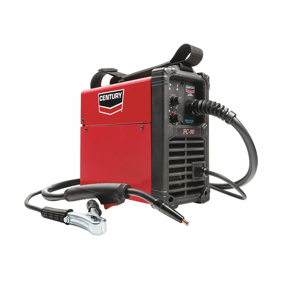
    FC 90 INSTALLATION INSTALLATION K3493-1 - FC-90 SPÉCIFICATIONS TECHNIQUES - REGISTRE COURANT DE SORTIE VITESSE DE DÉVIDAGE DU FIL 30-90 A 0 - 120 IPM TENSION DE CIRCUIT OUVERT DIAMÈTRE DE FIL APPROPRIÉ 19V (RMS) 0 030", 0,035" INTENSITÉ DE SORTIE...
  • Page 48: Choix D'un Emplacement Approprié

    FC 90 INSTALLATION Lire cette section d'installation dans sa totalité avant de commencer l'installation. INCLINAISON La machine doit être placée sur une surface plane et sûre. Mesures de Sécurité Ne pas essayer d'utiliser cet appareil avant d'avoir lu dans INDICE ENVIRONNEMENTAL leur totalité...
  • Page 49: Branchement De L'alimentation D'entrée

    La machine a un branchement d'entrée, le câble d'alimentation d'entrée. Le câble d'alimentation d'entrée se trouve sur l'arrière. La FC-90 est équipée d'un câble de 120 V de 6,0 ft. (1,8 m) de long, avec une fiche 5-15P de 15 Amp moulée sur le cordon.
  • Page 50: Chargement Et Enfilage Du Fil

    FC 90 INSTALLATION DÉTAILS SUR L'ENFILAGE DU FIL Se reporter à la Figure 3. CHARGEMENT ET ENFILAGE DU FIL Se reporter à la Figure 2. 4. Libérer la vis de réglage à ressort et faire tourner le bras du cylindre d'appui en l'éloignant du rouleau conducteur de Placer l'interrupteur de mise sous tension de la machine sur la dévidage du fil.
  • Page 51: Dépassement Du Fil

    FC 90 INSTALLATION DÉPASSEMENT DU FIL 10. Retirer la pointe de contact et la buse du pistolet. 11. Mettre la machine en MARCHE ("I"). 12. Redresser l'ensemble du câble du pistolet. 13. Appuyer sur l'interrupteur de la gâchette du pistolet et dévider le fil à...
  • Page 52: Fonctionnement

    FC 90 FONCTIONNEMENT FONCTIONNEMENT FONCTIONNEMENT DE LA MACHINE Une fois la machine installée conformément aux instructions, se Lire cette section dans sa totalité avant d'utiliser la reporter au Tableau B.1 et à l'Étiquette de Procédure située à CrossLinc Remote. l'intérieur de la porte du compartiment du galet d'entraînement de la machine pour obtenir des informations concernant l'installation, le matériel consommable et des astuces rapides pour le soudage.
  • Page 53: Liste Des Pièces De Rechange

    FC 90 FONCTIONNEMENT TABLEAU B.1 FCAW - Sans Gaz (Électrode Fourrée) Fil à Souder Lincoln NR-211-MP de 0,035 (Fil Fourré Innershield) Lincoln de 0,035 (0,9 mm) - Pièce No. KH712 Pointe de Contact Rainure Moletée de 0,9 mm - Lincoln Pièce No. KP4364-035 Rouleau Conducteur Rappel : retirer la pointe de contact avant de charger le fil.
  • Page 54: Entretien

    FC 90 DÉPANNAGE ENTRETIEN DÉPANNAGE AVERTISSEMENT COMMENT UTILISER LE GUIDE DE DÉPANNAGE AVERTISSEMENT LES CHOCS ÉLECTRIQUES peuvent être L’entretien et les Réparations ne doivent être effectués que mortels. par le Personnel formé par l’Usine Lincoln Electric. Des • COUPER l'alimentation d’entrée au réparations non autorisées réalisées sur cet appareil niveau de la source de puissance de peuvent mettre le technicien et l’opérateur de la machine en...
  • Page 55: Zones Possibles De Mauvais Réglage(S)

    FC 90 DÉPANNAGE Suivre les Instructions de Sécurité détaillées au début de ce manuel PROBLÈMES ZONES POSSIBLES DE MAUVAIS ACTION RECOMMANDÉE (SYMPTOMES) RÉGLAGE(S) Le cordon est trop épais (de La vitesse de déplacement est lente et/ou L'augmenter et maintenir une vitesse de déplacement façon intermittente).
  • Page 56 FC 90 DIAGRAMMES FRONT OF MACHINE REAR OF MACHINE...
  • Page 58 WARNING Do not touch electrically live parts or Keep flammable materials away. Wear eye, ear and body protection. electrode with skin or wet clothing. Insulate yourself from work and AVISO DE ground. Spanish PRECAuCION No toque las partes o los electrodos Mantenga el material combustible Protéjase los ojos, los oídos y el bajo carga con la piel o ropa moja-...
  • Page 59 WARNING Keep your head out of fumes. Turn power off before servicing. Do not operate with panel open or Use ventilation or exhaust to guards off. remove fumes from breathing zone. AVISO DE Spanish PRECAuCION Los humos fuera de la zona de res- Desconectar el cable de ali- No operar con panel abierto o piración.
  • Page 60: Politique D'assistance Au Client

    Susceptible d’être Modifié - Autant que nous le sachons, cette information est exacte au moment de l’impression. Prière de visiter le site www.lincolnelectric.com pour la mise à jour de ces informations. CENTURY EQUIPMENT 2345 Murphy Blvd. • Gainesville, GA 30504...

Ce manuel est également adapté pour:

12721

Table des Matières