Table des Matières
Publicité
Les langues disponibles
Les langues disponibles
Liens rapides
3B SCIENTIFIC
3B SCIENTIFIC
3B SCIENTIFIC® PHYSICS
3B SCIENTIFIC
3B SCIENTIFIC
Drehpendel nach Prof. Pohl 1002956
Bedienungsanleitung
06/18 ALF
bl
bm
bn
Das Drehpendel dient zur Untersuchung von freien,
erzwungenen und chaotischen Schwingungen bei ver-
schiedenen Dämpfungen.
Versuchsthemen:
• Freie Drehschwingungen bei verschiedenen Dämp-
fungen (Schwingfall mit mäßiger Dämpfung, ape-
riodische Schwingung und aperiodischer Grenzfall)
• Erzwungene Schwingungen und deren Resonanz-
kurven bei verschiedenen Dämpfungen
• Phasenverschiebung zwischen Erreger und Resona-
tor im Resonanzfall
• Chaotische Drehschwingungen
• Statische Bestimmung der Richtgröße D
• Dynamische Bestimmung des Trägheitsmoments J
1. Sicherheitshinweise
• Das Drehpendel bei der Entnahme aus der Verpa-
ckung nicht am Skalierring anfassen! Beschädi-
PHYSICS
PHYSICS
PHYSICS
PHYSICS
9
8
7
6
5
4
bo
bp
bq
br
1
Erregermotor
2
Drehknopf zur Feineinstellung der Erregerspannung
3
Drehknopf zur Grobeinstellung der Erregerspannung
4
Skalenring
5
Pendelkörper
6
Schneckenfeder
7
Zeiger zur Phasenlage des Erregers
8
Zeiger zur Phasenlage des Pendelkörpers
9
Zeiger für Auslenkung des Pendelkörpers
3
bl
Erreger
bm
Wirbelstrombremse
bn
Führungsschlitz und Schraube zur Einstellung der Erreger-
2
amplitude
bo
Schubstange
bp
Antriebsrad mit Exzenter
1
bq
4-mm-Sicherheitsbuchsen zum Messen der Erregerspannung
br
4-mm-Sicherheitsbuchsen zur Versorgung des Erregermotors
bs
4-mm-Sicherheitsbuchsen zur Versorgung der Wirbelstrom-
bremse
bs
gungsgefahr! Entnahme immer mit Entnahmehil-
fe (Innenverpackung) vornehmen!
• Zum Tragen des Drehpendels Gerät immer an der
Grundplatte halten.
• Maximal zulässige Versorgungsspannung des
Erregermotors (24 V DC) nicht überschreiten.
• Das Drehpendel keinen unnötigen mechanischen
Belastungen aussetzen.
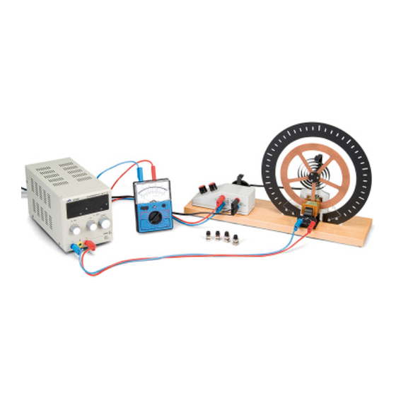
2. Beschreibung, technische Daten
Das Drehpendel nach Prof. Pohl besteht aus einem auf
einer hölzernen Grundplatte montiertem schwingen-
den System und einem Elektromotor. Das schwingen-
de System ist ein kugelgelagertes Kupferrad (5), das
über eine Spiralfeder (6), die das rücktreibende Mo-
ment liefert, mit dem Erregergestänge verbunden ist.
Zur Anregung des Drehpendels dient ein Gleichstrom-
motor mit grob- und fein einstellbarer Drehzahl, der
über einen Exzenter (14) mit Schubstange (13) die Spi-
1
Publicité
Table des Matières

Manuels Connexes pour 3B SCIENTIFIC PHYSICS 1002956

Sommaire des Matières pour 3B SCIENTIFIC PHYSICS 1002956
- Page 1 3B SCIENTIFIC 3B SCIENTIFIC 3B SCIENTIFIC® PHYSICS PHYSICS PHYSICS PHYSICS 3B SCIENTIFIC 3B SCIENTIFIC PHYSICS Drehpendel nach Prof. Pohl 1002956 Bedienungsanleitung 06/18 ALF Erregermotor Drehknopf zur Feineinstellung der Erregerspannung Drehknopf zur Grobeinstellung der Erregerspannung Skalenring Pendelkörper Schneckenfeder Zeiger zur Phasenlage des Erregers Zeiger zur Phasenlage des Pendelkörpers...
-
Page 2: Lieferumfang
ralfeder in periodischer Folge auseinanderzieht und treibende Drehmoment proportional zum Auslenk- winkel ϕ: zusammendrückt und so das Kupferrad in Schwingung versetzt. Für die Dämpfung wird eine elektromagneti- M = D · ϕ sche Wirbelstrombremse (11) verwendet. Ein Skalen- Der Proportionalitätsfaktor D (Winkelrichtgröße) lässt ring (4) mit Schlitzen und Skala in 2-mm-Teilung um- sich durch Messung des Auslenkwinkels und des aus- gibt das schwingende System;... - Page 3 Durch Einsetzen von δ = Λ / T , ω = 2 π / T Bei starker Dämpfung gibt es keine Amplituden- ω = 2 π / T in die Gleichung überhöhung. Für den System-Nullphasenwinkel Ψ gilt ω ω...
- Page 4 5. Versuchsbeispiele Ι Ι Ι Ι Ι = 0,2 A 5.1 Freie gedämpfte Drehschwingung ϕ • Zur Bestimmung des logarithmischen Dekrements ϕ Λ – – Ø – Λ werden die Amplituden in mehrfachen Durch- 0 –15 –15 –15 –15 –15 läufen gemessen und gemittelt.
- Page 5 • Die Eigenkreisfrequenz des Systems ω ergibt sich nach Messung der Periodendauer T aus ω = 2 π/T = 3,3069 Hz • Bei einer Motorspannung von 7,6 V findet die größ- te Auslenkung statt, d.h. der Resonanzfall tritt ein. • Dann wurde der gleiche Versuch mit zugeschalteter Wirbelstrombremse bei Ι...
- Page 6 PHYSICS PHYSICS PHYSICS 3B SCIENTIFIC 3B SCIENTIFIC PHYSICS Torsion Pendulum According to Prof. Pohl 1002956 Operating instructions 06/18 ALF Exciter motor Control knob for fine adjustment of the exciter voltage Control knob for coarse adjustment of the exciter voltage Scale ring...
-
Page 7: Scope Of Supply
unwinds the coil spring then compresses it again in a harmonic rotary oscillations the restoring torque is proportional to the deflection angle ϕ: periodic sequence and thereby initiates the oscillation of the copper wheel. The electromagnetic eddy cur- M = D · ϕ rent brake (11) is used for damping. - Page 8 By inserting δ = Λ / T , ω = 2 π / T and ω = 2 π / T Stronger damping does not result in excessive ampli- into the equation tude. For the system’s zero phase angle Ψ the following is true: ω...
- Page 9 5. Example experiments Ι Ι Ι Ι Ι = 0.2 A 5.1 Free damped rotary oscillations ϕ • To determine the logarithmic decrement Λ, the ϕ Λ – – Ø – amplitudes are measured and averaged out over 0 –15 –15 –15 –15...
- Page 10 • After measuring the period T the natural frequency of the system ω can be obtained from ω = 2 π/T = 3.3069 Hz • The most extreme deflection arises at a motor volt- age of 7.6 V, i.e. the resonance case occurs. •...
- Page 11 PHYSICS PHYSICS 3B SCIENTIFIC 3B SCIENTIFIC PHYSICS ® Pendule tournant d’après Prof. Pohl 1002956 Instructions d‘utilisation 06/18 ALF Moteur excitateur Bouton tournant pour le réglage fin de la tension d’excita- tion Bouton tournant pour le réglage grossier de la tension d’excitation...
-
Page 12: Matériel Fourni
traction (13), étire et comprime régulièrement le res- 3.2 Oscillation tournante harmonique sort spiral et fait ainsi osciller la roue en cuivre. Un Une oscillation est harmonique lorsque la force de rap- frein électromagnétique à courants de Foucault (11) pel est proportionnelle à la déviation. En présence d’os- est utilisé... -
Page 13: Oscillation Tournante Forcée
et ainsi le décrément logarithmique Λ: Cette fréquence résulte de δ ϕ ϕ ω ω ⋅ − Λ = ⋅ δ = ⋅ Eres ω ϕ ϕ ... - Page 14 5. Exemples d’expériences Ι Ι Ι Ι Ι = 0,2 A 5.1 Oscillation tournante amortie libre ϕ • Pour définir le décrément logarithmique Λ, mesu- ϕ Λ – – Ø – rer et déterminer les amplitudes en plusieurs pas- 0 –15 –15 –15 –15...
- Page 15 • D’après la mesure de la durée d’une période T, la fréquence angulaire propre du système ω résulte de l’équation suivante : ω = 2 π/T = 3,3069 Hz • La déviation maximale a lieu avec une tension de moteur de 7,6 V, c’est-à-dire qu’il y a résonance. •...
- Page 16 3B SCIENTIFIC® PHYSICS PHYSICS PHYSICS PHYSICS 3B SCIENTIFIC 3B SCIENTIFIC PHYSICS Pendolo di torsione del Prof. Pohl 1002956 Istruzioni per l’uso 06/18 ALF Motore ad eccitazione Manopola di microregolazione della tensione di eccitazione Manopola di macroregolazione della tensione di eccitazione Anello graduato:...
- Page 17 rale in sequenza periodica, mettendo in tal modo in chiamo è proporzionale alla deviazione. In caso di oscil- moto la ruota di rame. Per lo smorzamento si utilizza lazioni di torsione armoniche il momento torcente di richiamo è proporzionale all'angolo di deviazione ϕ: un freno elettromagnetico a corrente di Foucault (11).
- Page 18 Inserendo δ = Λ / T , ω = 2 π / T e ω = 2 π / T In caso di smorzamento potente non si verifica alcun nell'equazione incremento di ampiezza. Per l'angolo di fase zero del sistema Ψ vale ω...
- Page 19 5. Esempi di esperimenti Ι Ι Ι Ι Ι = 0,2 A 5.1 Oscillazione di torsione smorzata libera ϕ • Per la determinazione del decremento logaritmico ϕ Λ – – Ø – Λ le ampiezze vengono misurate in più flussi e ven- 0 –15 –15 –15...
- Page 20 • La frequenza del circuito proprio del sistema ω ottiene dalla misurazione del periodo T ω = 2 π/T = 3,3069 Hz • In caso di tensione del motore pari a 7,6 V ha luo- go la deviazione massima, ossia si verifica la riso- nanza.
- Page 21 PHYSICS PHYSICS PHYSICS 3B SCIENTIFIC 3B SCIENTIFIC PHYSICS Péndulo oscilatorio según Pohl 1002956 Instrucciones de uso 06/18 ALF Motor de excitación Botón para ajuste fino de la tensión de excitación Botón para ajuste grueso de la tensión de excitación Anillo graduado...
-
Page 22: Volumen De Suministro
ω presiona y estira el muelle espiral, en secuencias pe- frecuencia angular del excitador para E res riódicas, por medio de una palanca excéntrica (14), la máx. amplitud Ψ dotada de una biela (13), provocando de esta manera ángulo de fase cero del sistema la oscilación de la rueda de cobre. - Page 23 ϕ y para la amplitud tras n periodos ϕ = , se obtiene En el caso de las oscilaciones no amortiguadas, si se lo siguiente, con la relación ω = 2 π /T es igual a ω presenta el caso de resonancia (ω ), teóri- camente, la amplitud aumenta hasta el infinito, lo cual ϕ...
- Page 24 • Lo anterior se realiza atornillando las pesas al cuer- • Para la frecuencia propia ω es válido po del péndulo (5). π ω − δ ω = 3,307 Hz 5.2 Oscilación torsional de amortiguación libre •...
- Page 25 T = 1,9 s ϕ Tensión del motor V 15,2 Ι Ι Ι Ι Ι = 0,4 A 20,0 16,8 ϕ Tensión del motor V • La frecuencia circular propia del sistema ω se ob- tiene de la medición de la duración de periodo T a partir de: ω...
-
Page 26: Instruções Para O Uso
PHYSICS PHYSICS 3B SCIENTIFIC 3B SCIENTIFIC PHYSICS Pêndulo de torção segundo Prof. Pohl 1002956 Instruções para o uso 06/18 ALF Motor do excitador Botão rotativo para o ajuste fino da tensão do excitador Botão rotativo para o ajuste grosseiro da tensão do... - Page 27 ω numa seqüência periódica através de um excêntrico Freqüência circular para a amplitude máx. E res Ψ (14) com uma vara de impulso (13), levando assim a Ângulo de fase do sistema roda de cobre a oscilar. Para o amortecimento é utili- zado um freio de corrente parasita eletromagnético 3.2 Oscilações de torção harmônicas (11).
- Page 28 e a partir disso o decremento logarítmico Λ: freqüência resulta de δ ω ω ⋅ − ϕ ϕ Eres ω Λ = ⋅ δ = ⋅ ϕ ϕ ...
- Page 29 5. Exemplos de experiências Ι Ι Ι Ι Ι = 0,2 A 5.1 Oscilações de torção livres amortecidas ϕ • Para determinar o decremento logarítmico Λ, me- ϕ Λ – – Ø – dem-se e estabelece-se a média das amplitudes em 0 –15 –15 –15...
- Page 30 • A freqüência circular do sistema ω obtém-se pela medição da duração de período T ω = 2 π/T = 3,3069 Hz • Com uma tensão de motor de 7,6 V ocorre a maior distância angular, ou seja, ocorre o caso de resso- nância.