Faber FEG4916F Manuel D'instructions
Table des Matières
Les langues disponibles
Les langues disponibles
Engage Instruction Manual
WARNING: IF THE INFORMATION IN THESE INSTRUCTIONS ARE NOT
FOLLOWED EXACTLY, A FIRE OR EXPLOSION MAY RESULT CAUSING
PROPERTY DAMAGE, PERSONAL INJURY, OR LOSS OF LIFE.
Do not store or use gasoline or other flammable vapors and
liquids in the vicinity of this or any other appliance.
WHAT TO DO IF YOU SMELL GAS.
• Do not try to light any appliance.
• Do not touch any electrical switch; do not use any phone in
your building.
• Leave the building immediately.
• Immediately call your gas supplier from a neighbor's phone.
Follow the gas supplier's instructions.
• If you cannot reach your gas supplier, call the fire department.
Installation and service must be performed by a qualified
installer, service agency or the gas supplier.
GAS-FIRED
Certified to:
CSA 2.17-2017
ANSI Z21.88-2019
CSA 2.33-2019
DANGER
DANGER
DANGER
DANGER
HOT GLASS WILL
HOT GLASS WILL
HOT GLASS WILL
HOT GLASS WILL
CAUSE BURNS.
CAUSE BURNS.
CAUSE BURNS.
CAUSE BURNS.
DO NOT TOUCH GLASS
DO NOT TOUCH GLASS
DO NOT TOUCH GLASS
DO NOT TOUCH GLASS
UNTIL COOLED.
UNTIL COOLED.
UNTIL COOLED.
UNTIL COOLED.
NEVER ALLOW CHILDREN
NEVER ALLOW CHILDREN
NEVER ALLOW CHILDREN
NEVER ALLOW CHILDREN
TO TOUCH GLASS.
TO TOUCH GLASS.
TO TOUCH GLASS.
TO TOUCH GLASS.
A barrier designed to reduce the risk of burns from
A barrier designed to reduce the risk of burns from
A barrier designed to reduce the risk of burns from
A barrier designed to reduce the risk of burns from
the hot viewing glass is provided with this appliance
the hot viewing glass is provided with this appliance
the hot viewing glass is provided with this appliance
the hot viewing glass is provided with this appliance
and shall be installed for the protection of children
and shall be installed for the protection of children
and shall be installed for the protection of children
and shall be installed for the protection of children
and other-at risk individuals.
and other-at risk individuals.
and other-at risk individuals.
and other-at risk individuals.
Installer: Please complete the details on the back cover and
leave this manual with the homeowner.
Homeowner: Please keep these instructions for future reference.
FRENCH VERSION: Is available online at faberfires.com
FEG4916F
FEG5316L
FEG5316R
FEG5716B
7216450100R01
Chapitres
Table des Matières
Dépannage

Manuels Connexes pour Faber FEG4916F


Sommaire des Matières pour Faber FEG4916F
- Page 71 FEG4916F FEG5316L Manuel d’installation et d’utilisation FEG5316R FEG5716B DANGER DANGER DANGER AVERTISSEMENT : LE NON-RESPECT DES AVERTISSEMENTS DE SÉCURITÉ POURRAIT ENTRAÎNER DES BLESSURES GRAVES, LA MORT OU DES DOMMAGES MATÉRIELS. Ne pas entreposer ni utiliser d’essence ni d’autres vapeurs ou liquides inflammables dans le voisinage de cet appareil ou de tout autres appareil.
- Page 72 Table des matières CONSIGNES DE SÉCURITÉ . . . . . . . . . . . . . . . . . . . . . . . . . . . . . . . . . . . . . . . . . . . . . . . . . . . . . . . . . . . . . . . . . 4 Informations sur le foyer .
- Page 73 Table des matières Électricité et contrôle . . . . . . . . . . . . . . . . . . . . . . . . . . . . . . . . . . . . . . . . . . . . . . . . . . . . . . . . . . . . . . . . . . . 51 Schéma de câblage .
-
Page 74: Consignes De Sécurité
CONSIGNES DE SÉCURITÉ AVERTISSEMENT • L’appareil est chaud lorsqu’il fonctionne . Risque de une barrière de sécurité ; cette mesure empêchera brûlures graves . les tout petits, les jeunes enfants et toute autre personne à risque d’avoir accès à la pièce et aux •... - Page 75 CONSIGNES DE SÉCURITÉ AVERTISSEMENT • Seules les façades en option certifiées avec primaire du ou des brûleur(s) peut entraîner de la suie l’appareil doivent être installées sur l’appareil . et des dommages matériels . • Gardez le matériel d’emballage hors de portée des •...
- Page 76 Faber exige que l'installation soit espaces du bâtiment . effectuée par un installateur certifié NFI ou un installateur Faber certifié . 4 . Fermez les registres du foyer . Les installations qui ne suivent pas ces 5 . Allumez les sèche-linge et tout appareil non instructions ne seront pas couvertes par connecté...
-
Page 77: Informations Sur Le Foyer
Avec 175 ans de savoir-faire, d'innovations, d'une vision visionnaire et de notre passion, nous sommes devenus l'expert des feux . Faber est responsable des inventions qui sont devenues la norme dans le monde entier, et elles sont notre fierté et notre passion ! Les fabricants de feu de Faber développent les plus beaux feux ambiants . -
Page 78: Informations Sur L'installation
Informations sur l'installation IMPORTANT : L'installation suivante doit être effectuée par l'installateur qualifié et laissée au propriétaire de la propriété . Le modèle et le numéro de série de l'appareil se trouvent sur l'étiquette apposée sur le foyer . Information sur l'appareil Numéro de modèle Numéro de série Informations du propriétaire... -
Page 79: Journal De L'entretien
Informations sur le foyer Journal de l'entretien Date Notes... -
Page 80: Étiquette
Make sure glass is properly sealed. Follow installation instructions. et située dans une fente sous For use only with barrier(s) Part No.(s) 0443010100 - FEG4916F, 0443010200 & 044301300 - FEG5316L/R, 0443010400 & la grille inférieure dédiée à son 0443010300 (x2) -FEG5716B. -
Page 81: Dimensions Techniques
2" 6 5/8" 6 5/8" 6 5/8" 6 5/8" 1511 1511 59 1/2" 59 1/2" 1511 FEG4916F - Foyer au gaz linéaire à configuration de face 1511 59 1/2" 59 1/2" 1561 1561 61 7/16" 20 13/16" 61 7/16" 1561 20 13/16"... - Page 82 Dimensions techniques VENT 8"X5" VENT 8"X5" 29 3/4" 2" VENT 8"X5" 29 3/4" 2" 29 3/4" VENT 8"X5" 2" 29 3/4" 2" 6 5/8" 6 5/8" 6 5/8" 6 5/8" 1538 FEG5316L - Foyer au gaz linéaire à configuration gauche 1538 1538 60 9/16"...
- Page 83 Informations sur le foyer Dimensions techniques VENT 8"X5" 29 3/4" VENT 8"X5" 2" VENT 8"X5" VENT 8"X5" 29 3/4" 2" 29 3/4" 2" 29 3/4" 2" 6 5/8" 6 5/8" 6 5/8" 6 5/8" 1538 FEG5316R - Foyer au gaz linéaire encastrable à configuration droite 1538 60 9/16"...
- Page 84 Dimensions techniques VENT 8"X5" VENT 8"X5" 29 3/4" 2" VENT 8"X5" VENT 8"X5" 29 3/4" 2" 29 3/4" 2" 29 3/4" 2" 6 5/8" 6 5/8" 6 5/8" 6 5/8" 1565 FEG5716B - Foyer au gaz linéaire encastrable à configuration trois faces 1565 1565 1565...
-
Page 85: Fonctionnement
Fonctionnement Instructions de la télécommande Securite enfants Temps Indicateur de signal Mode thermostatique Securite enfants Temps Indicateur de signal État des piles Mode thermostatique Securite enfants Temps Indicateur de signal État des piles Mode thermostatique État des piles Ventilateur de circulation Minuterie Ventilateur de circulation Minuterie... - Page 86 MODE MANUEL (TÉLÉCOMMANDE) FEU DE FAIBLE INTENSITÉ ET DE FORTE INTENSITÉ DESIGNE INDICATION ▪ Pour passer à un feu de faible intensité, AVANT FONCTIONNEMENT double-cliquer sur le bouton 1. Veiller à ce que le bouton MANUEL situé sur la vanne ▪...
- Page 87 Fonctionnement MODES D’OPERATION MODE PROGRAMME Mode Thermostatique MARCHE : ▪ Presser le bouton La température ambiante est mesurée ▪ ou s’a che. 2 ON et comparée à la température réglée. La hauteur de la amme est ensuite automatiquement réglée pour qu’elle atteigne la température réglée.
- Page 88 PROGRAM MODE FONCTION 2 BRÛLEUR ÈME sélectionné L'électrovanne verrouillable s’ouvre automatiquement à RÉGLAGE HEURE MARCHE l’allumage ou après avoir coupé le système de sorte que le (PROGRAMME 1) : débit de gaz maximal parvienne aux deux brûleurs pour favoriser le système d’allumage. Après avoir appuyé sur le , , ON s’a che, s’a che bouton 2...
- Page 89 Fonctionnement FONCTION 2 BRÛLEUR ÈME L'électrovanne verrouillable s’ouvre automatiquement à l’allumage ou après avoir coupé le système de sorte que le débit de gaz maximal parvienne aux deux brûleurs pour favoriser le système d’allumage. Après avoir appuyé sur le bouton 2 Brûleur, le moteur tournera 7 secondes dans le ème sens ON jusqu’à...
-
Page 90: Piles De La Télécommande Et Du Récepteur
Piles de la télécommande et du récepteur Piles de la télécommande Piles du récepteur • 2 × AAA (piles alcalines recommandées) • 4 × AA (piles alcalines SEULEMENT) • Indicateur de piles faibles sur les combinés avec • Indicateur de piles faible : bips fréquents pendant écran 3 secondes lorsque le moteur tourne . -
Page 91: Étapes D'installation
Étapes d’installation 1 . Avant de commencer l’installation, assurez-vous d’avoir lu et compris toutes les informations AVERTISSEMENT du manuel . Ne démarrez pas l’installation si vous n’êtes pas sûr de l’un des sujets liés à l’installation . 2 . Déterminez les éléments suivants : •... -
Page 92: Préparation À L'installation
Déballage du foyer et contenu Retirer la caisse protectrice de la palette . Le foyer Faber est fourni avec le contenu suivant . Assurez-vous que tous les composants sont présents avant l'installation . Il se peut que tous les composants ne soient pas emballés exactement comme indiqué... -
Page 93: Emplacement Du Foyer
Préparation à l'installation Emplacement du foyer Une fois que le foyer a été réglé en position verticale, il peut être déplacé vers son emplacement d'installation final . • Assurez-vous que le module de commande est sécurisé et ne traîne pas sur le sol pendant le transport et le positionnement . -
Page 94: Terminaison D'évent
TOUJOURS maintenir les dégagements spécifiés autour des systèmes de ventilation et coupe-feu . Installer le bouclier mural et les coupe-feu de plafond comme spécifié . Taille de l’évent et du foyer Le foyer nécessitera un évent de 5 po × 8 po . Modèle Taille de l’évent FEG4916F FEG5316L FEG5316R FEG5716B... -
Page 95: Dégagements Combustibles Minimaux De L'évent
Terminaison d’évent Dégagements combustibles minimaux de l’évent • Dégagements d’évent horizontaux Un dégagement minimum de 3 po (76 mm) vers le haut et 1 po (26 mm) vers les côtés et le bas du tuyau de ventilation sur toutes les conduites horizontales vers les combustibles est requis . •... -
Page 96: Dégagements Minimaux Autour De L'évent
Dégagements minimaux autour de l'évent Exigences de dégagement minimum Canada¹ É .U .² Dégagement au-dessus du niveau du sol, véranda, véranda, terrasse ou 12 po (30 cm) 12 po (30 cm) balcon Dégagement d’une fenêtre ou d’une porte qui peut être ouverte 12 po (30 cm) 9 po (23 cm) Dégagement d’une fenêtre fermée en permanence... -
Page 97: Installation De L'appareil Avec Terminaison Horizontale
Terminaison d’évent Installation de l'appareil avec terminaison horizontale Ventilation 5 po x 8 po (systèmes de ventilation rigides) Dégagements minimaux de ventilation aux * Les dégagements notés doivent être maintenus ; combustibles sauf lors du passage à travers d'un mur, d'un Horizontal Top* 3 po (76 mm)* plafond ou à... - Page 98 Installation de l'appareil avec terminaison horizontale ! NOTE : a) La course horizontale de l’évent doit être de niveau ou avoir une élévation de 1/4 de pouce pour chaque 1 pied de course vers la terminaison . Ne jamais installer l'évent en pente descendante . Cela pourrait provoquer des températures élevées et présenter un risque d’incendie .
-
Page 99: Installation De L'appareil Avec Terminaison Verticale
Terminaison d’évent Installation de l'appareil avec terminaison verticale ! NOTE : Un dégagement supérieur de 3 po (76 mm) et un dégagement latéral inférieur de 2 po (51 mm) doivent être maintenus ; sauf lors du passage à travers un mur, un plafond ou à l’extrémité où l’utilisation d’un coupe- feu ou d’un coupe-feu mural réduit le dégagement requis à... -
Page 100: Longueur Du Tuyau
Installation de l'appareil avec terminaison verticale Glissez le solin sous les bardeaux (les bardeaux doivent chevaucher la moitié du solin) selon le Hauteur minimale de l’évent schéma 2 . Pente de la toiture Pieds Mètres 6 . Continuez à assembler les longueurs de tuyaux . plat à... -
Page 101: Exigences Minimales De Ventilation
Terminaison d’évent Exigences minimales de ventilation Configurations de ventilation autorisées pour les terminaisons de ventilation horizontales 40 pi V+H ≤ 40 pieds 38 ½ pi H ≤ 20 pieds (462 po) V + H sont mesurés à partir du centre des coudes de 35 pi ventilation Les coudes sont considérés... -
Page 102: Montée Horizontale (H)
Configurations de ventilation autorisées pour les terminaisons de ventilation horizontales Con gurations de ventilation autorisées pour les (pour tous les modèles) terminaisons de ventilation horizontales 40 pi V+H ≤ 40 pieds Zone 0 coudes H ≤ 20 pieds 35 pi V + H sont mesurés à... -
Page 103: Installation Et Planification De L'enceinte
Installation et planification de l'enceinte Matériau non combustible Matériau non combustible (⅝ po cloison sèche (⅝ po cloison sèche résistante résistante au feu de type X ou au feu de type X ou panneau de panneau de ciment ½ po) ciment ½... -
Page 104: Installation Du Foyer À Configuration De Face
Installation du foyer à configuration de face FEG4916F Charpente bois Charpente métal Référence pouces pouces 17 1/8 17 1/8 62 1/4 1581 61 1/4 1556 51 1/8 1300 51 1/8 1300 G (min .) 7 1/8 7 1/8 Installation du foyer à configuration droite ou gauche FEG5316L/FEG5316R Charpente bois Charpente métal... -
Page 105: Installation Du Foyer À Configuration Trois Faces
Installation et planification de l'enceinte Installation du foyer à configuration trois faces FEG5716B Charpente bois Charpente métal Référence pouces pouces 17 1/8 17 1/8 67 3/4 1720 66 3/4 1695 21 1/2 G (min .) 7 1/8 7 1/8 Précision des dimensions : Dimension A – Métal : hauteur du foyer + 1/4 po (6 mm) (pour manœuvrer) Dimension A –... -
Page 106: Dégagements
Dégagements Spécifications des matériaux Spécifications des matériaux incombustibles Les matériaux incombustibles sont ceux qui ne s'enflamment pas et ne brûlent pas . Ce sont des matériaux entièrement constitués d'acier, de fer, de brique, de tuile, de béton, d'ardoise, de verre ou de plâtre, ou toute combinaison de ceux-ci . -
Page 107: Dégagements Combustibles Minimaux Par Rapport Au Tuyau De Ventilation
à un poids non supporté et peut endommager le foyer ou briser la vitre . Un cadre ou un montage incorrect sur l’appareil annulera la garantie du produit . Veuillez consulter Faber... -
Page 108: Dégagements Dans L'enceinte
Dégagements dans l'enceinte AVERTISSEMENT Tous les matériaux à l'intérieur de la chasse et au-dessus du foyer doivent être incombustibles ou des combustibles recouverts uniquement . VUE DE FACE Dégagement à l'ossature métallique Le dégagement minimum par rapport à l'ossature métallique est de ½ po (13 mm) . -
Page 109: Dégagements Supplémentaires
Dégagements Dégagements dans l'enceinte Plafond de l'enceinte La partie supérieure intérieure de l'enceinte doit être recouverte d'un matériau incombustible (coupe-feu) . Aucun matériau combustible exposé n'est autorisé à l'intérieur de l'enceinte Dégagement au sol Le dégagement minimum du foyer au sol est de 3 po (8 cm) . ! NOTE : Installez l'appareil sur du métal dur, des panneaux de ciment, des cloisons sèches ou des surfaces en bois, en étendant toute la largeur et la profondeur . -
Page 110: Dégagement Du Manteau
Dégagement du manteau Le dégagement nécessaire pour un manteau en matériau combustible (par exemple, en bois) varie selon la profondeur et la hauteur du manteau . Utilisez le tableau et l'illustration suivants pour plus d'informations sur les exigences de dégagement du manteau pour les manteaux faits de matériaux combustibles installés à... -
Page 111: Finition Du Devant Du Foyer
Dégagements Finition du devant du foyer Un matériau de finition incombustible (tel que panneau de ciment de 1/2 po (13 mm), brique, pierre, tuile ou cloison sèche de 5/8 po de type X au minimum) DOIT être utilisé pour la finition autour de l'avant de l'appareil . Un matériau combustible couvert peut être utilisé... -
Page 112: Évacuation De Chaleur Et Prise D'air
Évacuation de chaleur et prise d'air Évacuation de chaleur Ce foyer nécessite une ou plusieurs évacuation(s) de chaleur situées au-dessus du foyer pour permettre à l'air chaud de refluer dans la pièce et de garder le mur du foyer frais . La surface totale d'évacuation de chaleur doit être d'au moins 200 po²... -
Page 113: Exemples D'évacuations De Chaleur Et De Prises D'air
Évacuation de chaleur et prise d'air Exemples d'évacuations de chaleur et de prises d'air Registres Mur court Les ouvertures à l'avant, sur les côtés ou à l'arrière Le mur n'atteint pas le plafond et reste ouvert (en choisir une ou plusieurs) peuvent être recouvertes en haut . -
Page 114: Informations Sur Le Montage Dessous Téléviseur
. Le montage d'un téléviseur au-dessus du foyer est basé sur la décision et la responsabilité du propriétaire . Faber ne sera pas tenu responsable des effets négatifs sur un téléviseur, des tableaux ou d'autres équipements situés à proximité de l'appareil . Il est de la responsabilité du propriétaire ou de l'installateur de vérifier que le téléviseur ou le tableau peut résister aux températures des murs sur le site... -
Page 115: Téléviseur Encastré
Informations sur le montage dessous téléviseur Téléviseur encastré Téléviseur encastré et foyer encastré Évacuation Évacuation Évacuation Évacuation de chaleur de chaleur de chaleur de chaleur Les câbles de Les câbles de Les câbles de Les câbles de télévision peuvent télévision peuvent télévision peuvent télévision peuvent être placés entre... -
Page 116: Foyer Encastré
Foyer encastré Aucun encastrement - avec manteau Exigences minimales pour l'installation d'un téléviseur sans encastrement : • Le téléviseur doit être au moins 11 po au-dessus de la vitre du foyer . Évacuation Évacuation • Un manteau d'au moins 1 po d'épaisseur et de 6 po de chaleur de chaleur de profondeur doit être installé... -
Page 117: Installation Du Gaz
Installation du gaz Général AVERTISSEMENT RISQUE D'INCENDIE OU D'EXPLOSION ! • Toute manipulation et installation de gaz doit être effectuée par un technicien d'entretien ou un installateur qualifié . • L'accumulation de gaz pendant la purge de la ligne pourrait s'enflammer . Assurer une ventilation adéquate . Assurez-vous qu'il n'y a pas de sources d'inflammation, d'étincelles ou de flammes nues . -
Page 118: Soupape À Gaz
Soupape à gaz Soupape à gaz Maxitrol GV60 Vis de réglage du gaz de la veilleuse (tourner Régulateur de pression ou − avec un tournevis) papillon des gaz (retirer la fiche en premier) Bouton de soupape Bouton manuel principal (MANUAL) Languette allumeuse connexion... -
Page 119: Installation À Haute Altitude
Installation du gaz Installation à haute altitude Ce foyer est testé et approuvé pour des installations à des altitudes de 0 à 4500 pieds (0 à 1372 m) au-dessus du niveau de la mer en utilisant les tailles d'orifice de brûleur standard . Au moment de l'installation, il faut déterminer si l'appareil doit être déclassé... -
Page 120: Commonwealth Du Massachusetts
Commonwealth du Massachusetts Exigences relatives à l’installation de détecteurs de 4 . INSPECTION . L’installation d’un appareil à gaz à sortie monoxyde de carbone et à l’affichage aux sorties d’évacuation horizontale au mur ne peut être approuvée d’évacuation pour l’État du Massachusetts par l’État ou l’inspecteur de gaz local à... -
Page 121: Électricité Et Contrôle
Électricité et contrôle Schéma de câblage Brûleur auxiliaire Brûleur principal Valve de verrouillage Câble d'allumage Câble du thermocouple SW Bloc interrupteur Câble du thermocouple TC Gas Supply Inlet Récepteur Contrôle combination Interrupteur Adaptateur Antenne Câble 8-fils mural (optionnel) (accessoire) Conduite de Fil électrique Source d'alimentation AVERTISSEMENT... -
Page 122: Interrupteur Mural - En Option
Interrupteur mural - en option Si vous souhaitez installer l'option d'interrupteur mural, vous devrez vous procurer la trousse accessoire d'interrupteur mural GV60 auprès de votre détaillant de foyer au gaz autorisé . L’interrupteur mural GV60 peut être acheté séparément en option pour contrôler le foyer . -
Page 123: Installation Finale
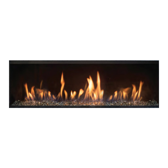
Arrangement du lit de braises Les pierres de verre sont incluses avec le foyer . Veuillez vous renseigner auprès de votre détaillant de foyer Faber pour les options de lit de braises supplémentaires . Suivez les instructions ci-dessous pour savoir comment ajouter et organiser des médias dans votre foyer :... - Page 124 OPTION BÛCHES ET CHARBON (vendus séparément) 1 . Disposez le charbon dans la configuration démontrée . 2 . Placer ensuite les bûches dans l'ordre comme démontré . Ne pas couvrir la veilleuse .
- Page 125 Installation finale Veilleuse - ne pas couvrir...
-
Page 126: Sceau Des Panneaux De Vitre
Sceau des panneaux de vitre Un tube d'adhésif en silicone est fourni avec le foyer pour une application sur toutes les connexions verre à verre des deux côtés des vitres . Schéma d'assemblage du • Le silicone a pour but de créer un joint, non de joint de vitre “coller”... -
Page 127: Retrait De Pièces
Retrait de pièces Retrait de l'écran de sécurité Suivez les instructions ci-dessous pour retirer l'écran de sécurité . ! NOTE : L'écran de sécurité peut être expédié séparément de l'appareil AVERTISSEMENT La barrière est conçue pour réduire le risque de brûlures de la vitre chaude et est fournie avec cet appareil . Il doit rester installé... -
Page 128: Retrait De La Vitre
Retrait de la vitre PRÉCAUTIONS DE SÉCURITÉ AVERTISSEMENT : Éteignez le foyer et laissez refroidir l'appareil avant d'essayer de retirer la vitre . MISE EN GARDE : Le verre céramique est très fragile et doit être manipulé avec précaution . AVERTISSEMENT : N'utilisez pas l'appareil avec la vitre enlevée, fissurée ou cassée . Le remplacement des panneaux doit être effectué... -
Page 129: Pièces De Rechange
2500990100RP Câble 8-fils 500 mm 2501010100RP Câble, Interrupteur-Récepteur TC 2501020100RP Câble, Interrupteur-Récepteur SW 2501020200RP Écrous d'accouplement pour vitre (jeu de 4) 8100370100RP FEG4916F 5904060100RP Vitre frontale (avec joint d'étanchéité) FEG5316L/FEG5316R 5904060200RP FEG5716B 5904060400RP FEG5316L/FEG5316R Vitre latérale (avec joint d'étanchéité) 5904060300RP... -
Page 130: Entretien
Entretien AVERTISSEMENT • Il est recommandé qu'un technicien d'entretien qualifié effectue une inspection de routine au début de chaque saison de chauffage . • Coupez l'alimentation avant de tenter l'entretien ou la réparation du foyer . • L'installation et l'entretien doivent être effectués par un installateur qualifié agréé, une agence de service ou un fournisseur de gaz . -
Page 131: Entretien Annuel
Entretien Entretien annuel Le fait de ne pas inspecter et de ne pas entretenir le foyer peut entraîner une combustion incorrecte et une situation potentiellement dangereuse . Nous recommandons que les procédures suivantes soient effectuées par un technicien qualifié . Entretien de la vitre •... -
Page 132: Configuration De La Flamme
Une configuration de flamme incorrecte aura de petites flammes probablement jaunes, n'entrant pas en contact approprié avec le brûleur arrière ou le capteur de flamme . ! NOTE : Si vous avez une configuration de flamme incorrecte, contactez Faber pour plus d'instructions . -
Page 133: Remplacement Des Bûches
• Ne pas nettoyer la vitre lorsqu'elle est chaude • L'utilisation de vitre de remplacement ne provenant pas de Faber annulera toutes les garanties des produits . • Des précautions doivent être prises pour éviter la rupture de la vitre . -
Page 134: Remplacement De La Vitre
Remplacement de la vitre Contactez Faber pour des pièces de rechange au besoin . Réinstallez selon les instructions fournies avec le remplacement . • Vérifiez pour des signes de condensation excessive, comme des gouttelettes d'eau se formant dans la doublure intérieure, et par la suite dégoulinant des joints, la condensation continue peut provoquer la corrosion des... -
Page 135: Guide De Dépannage
Guide de dépannage L’appareil ne s’allume pas à l’aide de la télécommande La télécommande doit apprendre un nouveau code Appuyez sur le bouton de réinitialisation du récepteur et maintenez-le enfoncé jusqu’à ce que vous entendiez 2 signaux acoustiques . Après le deuxième signal acoustique plus long, relâchez le bouton de réinitialisation et dans les 20 secondes suivantes, appuyez sur (flèche vers le bas) et maintenez la... - Page 136 Pas de flamme veilleuse et le contrôle continue de déclencher Présence d’air dans la ligne de la veilleuse Purger la ligne (démarrer l’allumage plusieurs fois) Vérifier l’éclateur ; vérifiez l’étincelle dans l’emplacement le long du câble . Aucune étincelle au brûleur de la veilleuse Vérifiez l’étincelle sur le récepteur en déconnectant le câble d’allumage du récepteur .
-
Page 137: Garantie
Garantie à vie limitée Faber étend cette garantie à vie limitée à l’acheteur d’origine de cet appareil à condition que le produit reste dans le lieu d’installation d’origine . Les articles couverts par cette garantie limitée et la durée de cette couverture sont indiqués dans le tableau ci-dessous . - Page 138 . choix de Faber par un distributeur agréé, un revendeur ou Dysfonctionnement, dommages ou problèmes liés aux un agent préapprouvé et affecté à condition que la pièce performances en raison des conditions environnementales, défectueuse soit retournée au distributeur, revendeur ou...
- Page 139 Enregistrement du produit et assistance client : Le recours exclusif de l’acheteur original en vertu de cette Merci d’avoir choisi un foyer Faber . Pour fournir le meilleur garantie et la seule obligation de Faber en vertu de cette support pour votre produit, nous vous demandons de remplir garantie, expresse ou implicite, contractuelle ou délictuelle,...