Scantronic KEY-K01 Guide D'installation
Table des Matières
Liens rapides
KEY-K01/KEY-KP01/KEY-KPZ01
Installation Instructions
UK
Guide d'installation
FR
Installatiehandleiding
NL
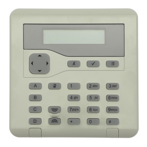
Programmable keys / Programmierbare Tasten / Touches programmables / Tasti programmabili / Programmeerbare toetsen
Figure 1. Key usage / Abb. 1. Verwendung der Tasten / Figure 1. Fonction des touches / Figura 1. Uso dei tasti / Afbeelding 1. Toetsgebruik
Figure 2. Removing the cover
Abb. 2. Die Abdeckung entfernen
Figure 2. Dépose du couvercle
Figura 2. Rimozione del coperchio
Afbeelding 2. Deksel verwijderen
Zones 1-2 (KEY-KPZ01 only) /
Zonen 1-2 (nur KEY-KPZ01) /
Zones 1-2 (KEY-KPZ01 uniquement) /
Zone 1-2 (solo KEY-KPZ01) /
Zones 1-2 (alleen KEY-KPZ01)
Volume / Lautstärke /
Volume / Volume / Volume
Figure 4. Keypad PCB / Abb. Keypad-Leiterplatte / Figure 4. Carte électronique du clavier (PCB) / Figura 4. PCB tastiera /
Scantronic
This product must be installed and maintained only by qualified service personnel. /
Dieses Produkt darf nur von qualifiziertem Servicepersonal installiert und gewartet werden. /
Ce produit doit être installé et entretenu par un technicien qualifié. /
Questo prodotto deve essere installato e sottoposto a manutenzione solo da personale di servizio qualificato. /
Dit product moet steeds door gekwalificeerde vakmensen worden geïnstalleerd en onderhouden.
LCD display / LCD-Display / Afficheur LCD / Display LCD / LCD-scherm
Navigation key / Navigationstaste / Touche de navigation / Tasto di navigazione / Navigatietoets
Programming keys / Programmiertasten / Touches de programmation / Tasti di programmazione / Programmeertoetsen
Unset key / Deaktivierungstaste / Touche de désarmement / Tasto disinserimento / Uitschakeltoets
Hold-up keys / Überfalltasten / Touches Agression / Tasti allarme panico / Overval-toetsen
Cable-entry holes (also on each side) / Öffnungen für Kabeleingang (auch an jeder Seite) / Trous de
passage de câble (de chaque côté) / Fori di ingresso cavi (anche su ciascun lato) / Kabelopening
(ook aan weerskanten)
Figure 3. Mounting the backplate / Abb. 3. Die Rückplatte montieren / Figure 3. Montage de la plaque
arrière / Figura 3. Montaggio della piastra posteriore / Afbeelding 3. Grondplaat monteren
LED
D1
D0
0V
12V
Z2
Z1
Afbeelding 4. Printplaat toetsenbord
Installationsanweisungen
DE
Istruzioni per l'installazione
IT
Use the supplied 3mm x 19mm (No4) screw for the tamper block.
Verwenden Sie die im Lieferumfang enthaltene Schraube (3 mm x 19 mm,
Nr. 4) für den Sabotageblock.
Utilisez la vis 3 mm x 19 mm (No4) fournie pour le bloc d'autoprotection.
Utilizzare la vite di 3 mm x 19 mm (N. 4) in dotazione per il blocco
antimanomissione.
Gebruik de meegeleverde 3 mm x 19 mm (Nr. 4) schroef als
sabotage-beveiliging.
Minimum 3 off 4mm x 25mm (No8) countersunk screws
Verwenden Sie mindestens drei Senkkopfschrauben (4 mm x 25 mm, Nr. 8)
Au moins 3 vis à tête fraisée 4 mm x 25 mm (No 8)
Minimo 3 viti svasate di 4 mm x 25 mm (N. 8)
Minimaal 3 van 4 mm x 25 mm (Nr. 8) verzonken schroeven
Address links / Adressverbindungen /
Cavaliers d'adressage / Collegamenti indirizzi /
Adresverbindingen
Brightness/ Helligkeit / Luminosité /
Luminosità / Helderheid
RS485 termination / RS485-Abschluss / Raccordement
RS485 / Terminazione RS485 / RS485-afsluiting
ADDR 4
ADDR 3
ADDR 2
BRIGHT
TERM
0V
12V
A
B
OP
Open-collector output (KEY-KPZ01 only) / Open-Kollektor-
Ausgang (nur KEY-KPZ01) / Sortie à collecteur ouvert
(KEY-KPZ01 uniquement) / Uscita open-collector (solo
KEY-KPZ01) / Open-collector uitgang (alleen KEY-KPZ01)
Bus device / Busgerät / Dispositif de
bus / Dispositivo bus / Busapparaat
Bus
Table des Matières

Manuels Connexes pour Scantronic KEY-K01


Sommaire des Matières pour Scantronic KEY-K01
- Page 1 KEY-K01/KEY-KP01/KEY-KPZ01 Installation Instructions Installationsanweisungen Guide d’installation Istruzioni per l’installazione Installatiehandleiding This product must be installed and maintained only by qualified service personnel. / Dieses Produkt darf nur von qualifiziertem Servicepersonal installiert und gewartet werden. / Ce produit doit être installé et entretenu par un technicien qualifié. / Questo prodotto deve essere installato e sottoposto a manutenzione solo da personale di servizio qualificato.
- Page 2 KEY-EP . Also enable EP The following options are available: Tamper (see Using the local menu ). The KEY-K01, KEY-KP01 and KEY-KPZ01 are wired ABCD LEDs Output keypads for use with i-on intrusion systems.
- Page 3 Alarmtönen ist fest eingestellt und kann nicht • Bevor Sie Kabel installieren, unterbrechen geändert werden. Das KEY-K01, KEY-KP01 und der KEY-KPZ01 Sie die Stromversorgung zur Steuereinheit sind verkabelte Keypads zur Verwendung mit Bevor Sie das Keypad öffnen, rufen Sie das inklusive der Batterie.
-
Page 4: Technische Daten
Reinigungsmittel. NF et A2P . Diese Option aktiviert bzw. deaktiviert die LEDs Technische Daten Les claviers KEY-K01, KEY-KP01 et KEY-KPZ01 hinter den ABCD-Tasten. Die LEDs zeigen den sont des claviers câblés destinés aux systèmes Aktivierungsstatus des Systems (zum Beispiel Versorgungsspannung: 12 VDC. -
Page 5: Entretien
Les connexions de zone ZFS (zone filaire • indiquent l’état d’armement du système (par KEY-K01 : 58 mA en alarme avec le supervisée), NF 4 fils et NF 2 fils sont prises exemple, un armement partiel de A illumine la rétroéclairage activé. 18 mA au repos avec le en charge. - Page 6 Introduzione uscita). Il volume dei toni di allarme è fisso. Collegare tutti i cavi al PCB (Figura 4). I KEY-K01, KEY-KP01 e KEY-KPZ01 sono tastierini Prima di aprire la tastiera, accedere al menu collegamenti del bus sono gli unici collegamenti cablati utilizzabili con i sistemi di rilevamento dell’Installatore (per evitare un allarme),...
-
Page 7: Specifiche Tecniche
EP Tamper (KEY-KP01/KEY-KPZ01) telefoondraden, computer-netwerkkabels, coaxkabels en voedingskabels voor sirenes Abilitare questa opzione se un lettore di De KEY-K01, KEY-KP01 en KEY-KPZ01 zijn en luidsprekers op afstand. prossimità esterno KEY-EP è collegato. Se bekabelde toetsenborden, geschikt voor i-on abilitata, la tastiera esegue il polling di KEY-EP •... -
Page 8: Specificaties
Voedingsspanning: 12Vdc. De volgende opties zijn beschikbaar: Stroomverbruik (max.): • LED’s ABCD KEY-K01: 58mA in alarm met heldere achtergrondverlichting. 18mA ruststroom met Via deze optie activeert of deactiveert u de LED’s achtergrondverlichting uit. achter de toetsen ABCD. De LED’s tonen de instelstatus van het systeem (als u bijv.