
Manuels Connexes pour Sentiotec Massivsauna


Sommaire des Matières pour Sentiotec Massivsauna
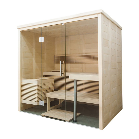
- Page 1 Massivsauna BALANCE VIEW LARGE 208 x 206 x 204 cm MONTAGEANLEITUNG Deutsch BALANCE-V-L Version 11/19 Artikel-Nr. 1-051-273...
-
Page 2: Table Des Matières
Inhaltsverzeichnis 1. Montage Vorbereitung 1.1. Benötigtes Werkzeug 1.2. Wartung und Reinigung 1.3. Entsorgung 1.4. Stückliste BALANCE VIEW LARGE 2. Montage der Kabine 2.1. Montage des Bodenrahmens 2.2. Montage der Wandelemente 2.3. Montage Dach 2.4. Montage Lüftungsschieber 2.5. Montage Inneneinrichtung 2.6. Montage Zubehör 2.7. -
Page 3: Montage Vorbereitung
Lesen Sie diese Montageanleitung gut durch und bewahren Sie sie in der Nähe der Sauna auf. So können Sie jederzeit Produktinformationen nachlesen. Sie finden diese Montageanleitung auch im Downloadbereich unserer Webseite auf www.sentiotec.com/downloads. Wichtige Hinweise: ● Kontrollieren Sie, bevor Sie mit der Arbeit beginnen, anhand der Stückliste, ob alle Einzelteile auch tatsächlich mitgeliefert wurden. -
Page 4: Benötigtes Werkzeug
Montageanleitung S. 4/32 1.1. Benötigtes Werkzeug ● Hammer und Beilageholz oder einen Gummihammer ● Akkuschrauber mit Bits für Kreuzschrauben und Torx ● Rollmaßband ● Bohrer mit Durchmesser 3 mm, 10 mm, 20 - 30 mm (für Stromkabel Saunaofen) ● Wasserwaage ●... -
Page 5: Wartung Und Reinigung
Montageanleitung S. 5/32 1.2. Wartung und Reinigung ● Die Sauna sollte mit einem feuchten Tuch gereinigt werden. Verwenden Sie nur warmes Wasser - keine Reinigungsmittel. ● Wird die Sauna längere Zeit nicht benutzt, empfehlen wir, die Kabine einmal im Monat aufzuheizen. Harzgallen sind kein Reklamationsgrund. -
Page 6: Stückliste Balance View Large
Montageanleitung S. 6/32 1.4. Stückliste BALANCE VIEW LARGE Az Bezeichnung Maß Bodenrahmen 2 Bodenrahmen 198 x 9 x 4 cm 1 Bodenrahmen 204 x 9 x 4 cm Wandelemente 3 Wandelement A/A mit Multiclip 193 x 48 x 4 cm 4 Wandelement A/A 193 x 48 x 4 cm 1 Elektroelement A/A mit Multiclip... - Page 7 Montageanleitung S. 7/32 Az Bezeichnung Maß Inneneinrichtung 2 Bänk 195 x 62 x 9 cm 1 Bank 28 x 62 x 9 cm 1 Bankblende 62 x 9 x 2 cm 1 Nirofuß 83,5 x 6 cm 2 Rückenlehne 185 x 26 x 5 cm 1 Banksichtblende 195 x 35 x 5 cm 1 Ofenschutzgitter...
-
Page 8: Montage Der Kabine
Montageanleitung S. 8/32 2. Montage der Kabine Die Kabine kann „links“ oder „rechts“ aufgebaut werden, beachten Sie dazu die Grundrisspläne auf Seite 30 und Seite 31. 2.1. Montage des Bodenrahmens 204 cm... -
Page 9: Montage Der Wandelemente
Montageanleitung S. 9/32 2.2. Montage der Wandelemente Die Ecksteher werden mittels „Multiclips“ mit den Wandelementen verbunden. Die weiteren Wandelemente sind mit Nut und Feder verbunden und werden miteinander verschraubt. A bezeichnet immer die Sichtseite, dies ist auf der Oberseite der Wand- elemente gekennzeichnet. - Page 10 Montageanleitung S. 10/32 Montage Ecksteher mit Wandelement Montieren Sie die Wandelemente mit den Eckstehern am Boden vor und setzen Sie diese Ecken dann auf den Bodenrahmen auf. Stecken Sie den Ecksteher von oben nach unten auf die Wandelemente. Achten Sie dabei auf die korrekte Ausrichtung der „Multiclips“ (siehe unten). Der Eck- steher muss bündig mit den Wandelementen sein.
- Page 11 Montageanleitung S. 11/32 Montage Wandelemente Das Elektroelement hat Bohrungen zum Verlegen der Kabel. Position siehe Grundrisspläne auf Seite 30 und Seite 31. Elektroelement (Grundriss „links“)
- Page 12 Montageanleitung S. 12/32 Steher für Glas...
- Page 13 Montageanleitung S. 13/32 Verschrauben der Wandelemente Überprüfen Sie die rechten Winkel, bevor Sie die Wandelemente verschrauben. Beachten Sie den Tipp auf Seite 4. Bohrer 3 mm, 7 Stk. Schrauben 4 x 70 mm Grundriss „links“...
- Page 14 Montageanleitung S. 14/32 Glaselemente Beachten Sie, dass Sie mit dem Einbau des Glaselements „Glas mit Bohrungen für Türbänder“ die Richtung der Türöffnung festlegen. Die untere Bohrung für das Türband ist in 26,3 cm Höhe. Element oberhalb der Tür 192 x 10,1 x 4 cm...
- Page 15 Montageanleitung S. 15/32 Bohrer 3 mm, 2 Stk. Schrauben 4 x 70 mm...
-
Page 16: Montage Dach
Montageanleitung S. 16/32 2.3. Montage Dach Dachauflageleisten 16 Stk. Schrauben 4 x 70 mm... - Page 17 Montageanleitung S. 17/32 Dachelemente Bohrer 3 mm, 20 Stk. Schrauben 4 x 70 mm...
-
Page 18: Montage Lüftungsschieber
Montageanleitung S. 18/32 2.4. Montage Lüftungsschieber Bohrer 3 mm, 4 Stk. Schrauben 3 x 40 mm 2.5. Montage Inneneinrichtung Bankauflageleisten Bohrer 3 mm, 3 Stk. Schrauben 5 x 70 mm 2 Stk. Schrauben 4 x 60 mm... - Page 19 Montageanleitung S. 19/32 3 Stk. Schrauben 5 x 70 mm 3 Stk. Schrauben 5 x 70 mm 2 Stk. Schrauben 4 x 60 mm...
- Page 20 Montageanleitung S. 20/32 3 Stk. Schrauben 5 x 70 mm 15 cm 3 Stk. Schrauben 5 x 70 mm...
- Page 21 Montageanleitung S. 21/32 Banksichtblende 2 Stk.Schrauben 3,5 x 50 mm...
- Page 22 Montageanleitung S. 22/32 Bank 6 Stk. Schrauben 3,5 x 35 mm...
- Page 23 Montageanleitung S. 23/32...
- Page 24 Montageanleitung S. 24/32 Rückenlehne Bohrer 3 mm, 4 Stk. Schrauben 3 x 40 mm...
- Page 25 Montageanleitung S. 25/32 ca. 25 cm Bohrer 3 mm, 4 Stk. Schrauben 3 x 40 mm...
-
Page 26: Montage Zubehör
Montageanleitung S. 26/32 2.6. Montage Zubehör Ofenschutzgitter Bohren Sie vor der Montage des Ofenschutzgitters den Auslass für das Ofenkabel im Elektroelement. 6 Stk. Schrauben 3,5 x 35 mm 6 Stk. Schrauben 3,5 x 35 mm... -
Page 27: Montage Glastür
Montageanleitung S. 27/32 2.7. Montage Glastür Die untere Bohrung des Türgriffs ist in 92,4 cm Höhe. Die Ausrichtung der Beschläge wird durch die Justierung / Drehung der beiden Kunststoffeinlagen vorgenommen. - Page 28 Montageanleitung S. 28/32 Türgriff Die Türgriffe werden von innen miteinander verschraubt. Silikonring in Bohrungen einlegen Kunststoff-Beilagscheiben bei Niro-Griff beilegen Türmagnet und Überschubblech...
-
Page 29: Montage Dachkranz
Montageanleitung S. 29/32 2.8. Montage Dachkranz Montieren Sie den Dachkranz erst nachdem Sie die Kabel zum Saunaofen und zur Saunasteuerung eingezogen haben. Möglicherweise muss die Leiste beim Elektroelement ausgeschnitten werden. Bohrer 3 mm, 12 Stk. Schrauben 3 x 40 mm 2.9. -
Page 30: Grundriss
Montageanleitung S. 30/32 3. Grundriss 3.1. Grundriss „links“... -
Page 31: Grundriss „Rechts
Gebrauchsanweisung für den Anwender S. 31/32 3.2. Grundriss „rechts“... -
Page 32: Änderungen Bei Montage Grundriss „Rechts
Gebrauchsanweisung für den Anwender S. 32/32 3.3. Änderungen bei Montage Grundriss „rechts“ Tausch Elektroelement mit Wandelement A/A mit Multiclip (Seite 11) Entfernen Sie die Fremde Feder vom Wandelement A/A mit Multiclip und set- zen Sie diese beim Elektroelement ein. Wandelement A/A mit Multiclip Fremde Feder Elektroelement - - -48 0 -- -... - Page 33 Solid wood sauna BALANCE VIEW LARGE 208 x 206 x 204 cm INSTRUCTIONS FOR INSTALLATION AND USE English BALANCE-V-L Version 11/19 Ident. no. 1-051-273...
- Page 34 Table of Contents 1. Preparing for installation 1.1. Tools required 1.2. Maintenance and cleaning 1.3. Disposal 1.4. BALANCE VIEW LARGE parts list 2. Cabin installation 2.1. Base frame installation 2.2. Wall element assembly 2.3. Roof installation 2.4. Ventilation slit installation 2.5.
-
Page 35: Preparing For Installation
These assembly instructions can also be found in the downloads section of our website: www.sentiotec.com/downloads. Important note: ● Before you begin work, check the parts list to ensure that all the individual parts have been delivered. -
Page 36: Tools Required
Instructions for installation and use p. 4/32 1.1. Tools required ● Hammer with a wooden head or a mallet ● Cordless screwdriver with bits for cross-head screws and Torx ● Roller tape measure ● Drill bits with a diameter of 3 mm, 10 mm, 20 - 30 mm (for sauna heater power cable) ●... -
Page 37: Maintenance And Cleaning
Instructions for installation and use p. 5/32 1.2. Maintenance and cleaning ● The sauna should be cleaned with a damp cloth. Only use warm water – no cleaning products. ● We recommend heating the cabin once a month if the sauna is not used for a long time. -
Page 38: Balance View Large Parts List
Instructions for installation and use p. 6/32 1.4. BALANCE VIEW LARGE parts list Name Dimensions No. of items Base frame 2 Base frame 198 x 9 x 4 cm 1 Base frame 204 x 9 x 4 cm Wall elements 3 A/A wall element with Multiclip 193 x 48 x 4 cm 4 A/A wall element... - Page 39 Instructions for installation and use p. 7/32 Name Dimensions No. of items Interior fittings 2 Bench 195 x 62 x 9 cm 1 Bench 28 x 62 x 9 cm 1 Bench blind 62 x 9 x 2 cm 1 Stainless foot 83.5 x 6 cm 2 Backrests 185 x 26 x 5 cm...
-
Page 40: Cabin Installation
Instructions for installation and use p. 8/32 2. Cabin installation The cabin can have a right or left set-up; please note the corresponding floor plans on Page 30 and Page 31. 2.1. Base frame installation 204 cm... -
Page 41: Wall Element Assembly
Instructions for installation and use p. 9/32 2.2. Wall element assembly The corner posts are connected to the wall elements using Multiclips. The other wall elements are connected tongue and groove and are screwed together. A always refers to the visible side. This is labelled on the top side of the wall elements. - Page 42 Instructions for installation and use p. 10/32 Installing corner posts with wall elements Pre-assemble the wall elements with the corner posts on the floor and then place these posts on the base frame. Insert the corner post from above down onto the wall elements. When doing this, ensure that the Multiclips are correctly aligned (see below).
- Page 43 Instructions for installation and use p. 11/32 Installing wall elements The electrical element has drill holes for laying cables. For the position see floor plans on Page 30 and Page 31. Electrical element (“left” floor plan)
- Page 44 Instructions for installation and use p. 12/32 Post for glass...
- Page 45 Instructions for installation and use p. 13/32 Screwing wall elements together Check the right angle before screwing the wall elements together. Observe the tip on page 4. 3 mm drill bit, 7 screws 4 x 70 mm Left floor plan...
- Page 46 Instructions for installation and use p. 14/32 Glass elements Note that when installing the glass element “glass with holes drilled for door hinges”, you are defining the direction in which the door will open. The bottom drill hole for the door hinge is 26.3 cm high. Element above the door 192 x 10.1 x 4 cm...
- Page 47 Instructions for installation and use p. 15/32 3 mm drill bit, 2 screws 4 x 70 mm...
-
Page 48: Roof Installation
Instructions for installation and use p. 16/32 2.3. Roof installation Roof support slats 16 screws 4 x 70 mm... - Page 49 Instructions for installation and use p. 17/32 Roof elements 3 mm drill bit, 20 screws 4 x 70 mm...
-
Page 50: Ventilation Slit Installation
Instructions for installation and use p. 18/32 2.4. Ventilation slit installation 3 mm drill bit, 4 screws 3 x 40 mm 2.5. Installing interior fittings Bench support slats 3 mm drill bit, 3 screws 5 x 70 mm 2 screws 4 x 60 mm... - Page 51 Instructions for installation and use p. 19/32 3 screws 5 x 70 mm 3 screws 5 x 70 mm 2 screws 4 x 60 mm...
- Page 52 Instructions for installation and use p. 20/32 3 screws 5 x 70 mm 15 cm 3 screws 5 x 70 mm...
- Page 53 Instructions for installation and use p. 21/32 Bench screen 2 screws 3.5 x 50 mm...
- Page 54 Instructions for installation and use p. 22/32 Bench 6 screws 3.5 x 35 mm...
- Page 55 Instructions for installation and use p. 23/32...
- Page 56 Instructions for installation and use p. 24/32 Backrests 3 mm drill bit, 4 screws 3 x 40 mm...
- Page 57 Instructions for installation and use p. 25/32 approx. 25 cm 3 mm drill bit, 4 screws 3 x 40 mm...
-
Page 58: Installing Accessories
Instructions for installation and use p. 26/32 2.6. Installing accessories Heater protection grille Before installing the heater protection grille, drill the outlet for the heater cable in the electrical element. 6 screws 3.5 x 35 mm 6 screws 3.5 x 35 mm... -
Page 59: Installing Glass Door
Instructions for installation and use p. 27/32 2.7. Installing glass door The bottom drill hole of the door handle is 92.4 cm high. The alignment of the fittings is achieved by adjusting / rotating both plastic inserts. - Page 60 Instructions for installation and use p. 28/32 Door handle The door handles are screwed together from the inside. Insert silicone ring in the drill holes Attach plastic washers on the stainless steel handle Door magnet and sleeve plate...
-
Page 61: Installing Roof Trim
Instructions for installation and use p. 29/32 2.8. Installing roof trim Install the roof trim only after you have inserted the cable to the sauna heater and to the sauna control unit. The slat on the electrical element may possibly have to be cropped. 3 mm drill bit, 12 screws 3 x 40 mm 2.9. -
Page 62: Floor Plan
Instructions for installation and use p. 30/32 3. Floor plan 3.1. Left floor plan... -
Page 63: Right Floor Plan
Instructions for installation and use p. 31/32 3.2. Right floor plan... -
Page 64: Changes For The Right Floor Plan Installation
Instructions for installation and use p. 32/32 3.3. Changes for the right floor plan installation Exchanging the electrical element with the A/A wall element with Multiclip (Page 32) Remove the external tongue element from the A/A wall element with Multiclip and insert it in the electrical element. A/A wall element with Multiclip External tongue element Electrical element... - Page 65 Sauna en bois massif BALANCE VIEW LARGE 208 x 206 x 204 cm INSTRUCTIONS DE MONTAGE ET MODE D’EMPLOI Français BALANCE-V-L Version 11/19 d’ident. 1-051-273...
- Page 66 Table des matières 1. Préparation du montage 1.1. Outils requis 1.2. Entretien et nettoyage 1.3. Élimination 1.4. Nomenclature BALANCE VIEW LARGE 2. Montage de la cabine 2.1. Montage du cadre de plancher 2.2. Montage des éléments muraux 2.3. Montage du toit 2.4.
-
Page 67: Préparation Du Montage
Vous avez ainsi accès à tout moment aux informations sur le produit. Vous trouverez également ces instructions de montage dans la rubrique de téléchargement de notre site Internet www.sentiotec.com/downloads. Remarques importantes : ● Avant de commencer les travaux, vérifiez au moyen de la nomenclature si toutes les pièces ont bien été... -
Page 68: Outils Requis
Instructions de montage et mode d’emploi p. 4/32 1.1. Outils requis ● Marteau et cales ou maillet en caoutchouc ● Visseuse électrique avec bits pour vis en croix et Torx ● Ruban de mesure ● Foret de 3 mm de diamètre, 10 mm, 20 - 30 mm (pour câble électrique poêle de sauna) ●... -
Page 69: Entretien Et Nettoyage
Instructions de montage et mode d’emploi p. 5/32 1.2. Entretien et nettoyage ● Le sauna doit être nettoyé au moyen d’un chiffon humide. N’utilisez que de l’eau chaude, pas de détergent. ● Si le sauna n’est pas utilisé pendant une période prolongée, nous recom- mandons de chauffer la cabine une fois par mois. -
Page 70: Nomenclature Balance View Large
Instructions de montage et mode d’emploi p. 6/32 1.4. Nomenclature BALANCE VIEW LARGE Az Désignation Dimensions Cadre de plancher 2 Cadre de plancher 198 x 9 x 4 cm 1 Cadre de plancher 204 x 9 x 4 cm Éléments muraux 3 Élément mural A/A avec multiclip 193 x 48 x 4 cm 4 Élément mural A/A... - Page 71 Instructions de montage et mode d’emploi p. 7/32 Az Désignation Dimensions Équipement intérieur 2 Banc 195 x 62 x 9 cm 1 Banc 28 x 62 x 9 cm 1 Cache pour banc 62 x 9 x 2 cm 1 Pied Niro 83,5 x 6 cm 2 Dossier 185 x 26 x 5 cm...
-
Page 72: Montage De La Cabine
Instructions de montage et mode d’emploi p. 8/32 2. Montage de la cabine La cabine peut être montée « à gauche » ou « à droite ». Référez-vous aux plans Page 30 et Page 31. 2.1. Montage du cadre de plancher 204 cm... -
Page 73: Montage Des Éléments Muraux
Instructions de montage et mode d’emploi p. 9/32 2.2. Montage des éléments muraux Fixez les montants d’angle aux éléments muraux au moyen des « multiclips ». Les autres éléments muraux sont reliés par des rainures et des languettes, et sont vissés les uns aux autres. A désigne toujours le côté... - Page 74 Instructions de montage et mode d’emploi p. 10/32 Montage des montants d’angle sur les éléments muraux Prémontez les éléments muraux et les montants d’angle au sol, puis placez ces angles sur le cadre de plancher. Placez le montant d’angle du haut vers le bas sur les éléments muraux. Assurez-vous que l’orientation des «...
- Page 75 Instructions de montage et mode d’emploi p. 11/32 Montage des éléments muraux Des trous sont prévus sur l’élément électrique afin de poser le câble. Pour la position, consultez Page 30 et Page 31. Élément électrique (Plan « à gauche »)
- Page 76 Instructions de montage et mode d’emploi p. 12/32 Montant pour verre...
- Page 77 Instructions de montage et mode d’emploi p. 13/32 Vissage des éléments muraux Contrôlez les angles droits avant de visser les éléments muraux. Consultez le conseil page 4. Foret de 3 mm, 7 vis 4 x 70 mm Plan « à gauche »...
- Page 78 Instructions de montage et mode d’emploi p. 14/32 Éléments en verre Prenez bien en compte le sens d’ouverture de la porte lors du montage de l’élément en verre « Verre avec alésage pour charnières ». L’alésage inférieur de la charnière se trouve à une hauteur de 26,3 cm. Élément au-dessus de la porte 192 x 10,1 x 4 cm...
- Page 79 Instructions de montage et mode d’emploi p. 15/32 Foret de 3 mm, 2 vis 4 x 70 mm...
-
Page 80: Montage Du Toit
Instructions de montage et mode d’emploi p. 16/32 2.3. Montage du toit Baguettes d’appui de toit 16 vis 4 x 70 mm... - Page 81 Instructions de montage et mode d’emploi p. 17/32 Éléments du toit Foret de 3 mm, 20 vis 4 x 70 mm...
-
Page 82: Montage Du Registre D'aération
Instructions de montage et mode d’emploi p. 18/32 2.4. Montage du registre d’aération Foret de 3 mm, 4 vis 3 x 40 mm 2.5. Montage de l’équipement intérieur Baguettes d’appui de banc Foret de 3 mm, 3 vis 5 x 70 mm 2 vis 4 x 60 mm... - Page 83 Instructions de montage et mode d’emploi p. 19/32 3 vis 5 x 70 mm 3 vis 5 x 70 mm 2 vis 4 x 60 mm...
- Page 84 Instructions de montage et mode d’emploi p. 20/32 3 vis 5 x 70 mm 15 cm 3 vis 5 x 70 mm...
- Page 85 Instructions de montage et mode d’emploi p. 21/32 Écran de banc 2 vis 3,5 x 50 mm...
- Page 86 Instructions de montage et mode d’emploi p. 22/32 Banc 6 vis 3,5 x 35 mm...
- Page 87 Instructions de montage et mode d’emploi p. 23/32...
- Page 88 Instructions de montage et mode d’emploi p. 24/32 Dossier Foret de 3 mm, 4 vis 3 x 40 mm...
- Page 89 Instructions de montage et mode d’emploi p. 25/32 Env. 25 cm Foret de 3 mm, 4 vis 3 x 40 mm...
-
Page 90: Montage Des Accessoires
Instructions de montage et mode d’emploi p. 26/32 2.6. Montage des accessoires Grilles de protection de poêle Avant le montage de la grille de protection du poêle, percez la sortie pour le câble du poêle dans l’élément électrique. 6 vis 3,5 x 35 mm 6 vis 3,5 x 35 mm... -
Page 91: Montage De La Porte En Verre
Instructions de montage et mode d’emploi p. 27/32 2.7. Montage de la porte en verre L’alésage inférieur de la poignée de porte se trouve à une hauteur de 92,4 cm. L’orientation des ferrures est effectuée en ajustant/tour- nant les deux armatures en plastique. - Page 92 Instructions de montage et mode d’emploi p. 28/32 Poignée de porte Les poignées sont vissées ensemble depuis l’intérieur. Introduction de la bague en silicone Pose des rondelles de calage dans les alésages en plastique pour poignée inox Aimant de porte et tôle extérieure...
-
Page 93: Montage De La Couronne
Instructions de montage et mode d’emploi p. 29/32 2.8. Montage de la couronne Ne montez la couronne qu’après avoir inséré les câbles vers le poêle de sauna et la commande de sauna. La baguette au niveau de l’élément électrique doit éventuellement être coupée. Foret de 3 mm, 12 vis 3 x 40 mm 2.9. -
Page 94: Plan
Instructions de montage et mode d’emploi p. 30/32 3. Plan 3.1. Plan « à gauche »... -
Page 95: Plan « À Droite
Instructions de montage et mode d’emploi p. 31/32 3.2. Plan « à droite »... -
Page 96: Modifications Lors Du Montage Selon Le Plan « À Droite
Instructions de montage et mode d’emploi p. 32/32 3.3. Modifications lors du montage selon le plan « à droite » Remplacement d’un élément électrique par un élément mural A/A avec multiclip (Page 32) Retirez la languette supplémentaire de l’élément mural A/A avec multiclip et la placer sur l’élément électrique. - Page 97 Sauna in legno massiccio BALANCE VIEW LARGE 208 x 206 x 204 cm ISTRUZIONI DI MONTAGGIO E PER L’USO Italiano BALANCE-V-L Versione 11/19 N. ident. 1-051-273...
- Page 98 Indice 1. Preparazione per il montaggio 1.1. Attrezzi necessari 1.2. Manutenzione e pulizia 1.3. Smaltimento 1.4. Elenco dei pezzi BALANCE VIEW LARGE 2. Montaggio della cabina 2.1. Montaggio del telaio di base 2.2. Montaggio degli elementi parete 2.3. Montaggio del tetto 2.4.
-
Page 99: Preparazione Per Il Montaggio
Le presenti istruzioni di montaggio si trovano anche nella sezione download del nostro sito web all’indirizzo: www.sentiotec.com/downloads. Indicazioni importanti: ● Prima di iniziare i lavori, controllare in base all’elenco dei pezzi se tutti i singoli componenti sono stati effettivamente forniti. -
Page 100: Attrezzi Necessari
Istruzioni di montaggio e per l’uso P. 4/32 1.1. Attrezzi necessari ● Martello e pezzo di legno oppure martello in gomma ● Avvitatore elettrico con punte per viti con testa a croce e viti Torx ● Metro a nastro avvolgibile ●... -
Page 101: Manutenzione E Pulizia
Istruzioni di montaggio e per l’uso P. 5/32 1.2. Manutenzione e pulizia ● La sauna deve essere pulita con un panno umido. Utilizzare solo acqua calda senza detergenti. ● Se la sauna non viene utilizzata per un tempo prolungato, si consiglia di riscaldare la cabina una volta al mese. - Page 102 Istruzioni di montaggio e per l’uso P. 6/32 1.4. Elenco dei pezzi BALANCE VIEW LARGE Pz. Denominazione Dimensioni Telaio di base 2 Telaio di base 198 x 9 x 4 cm 1 Telaio di base 204 x 9 x 4 cm Elementi parete 3 Elemento parete A/A con multiclip 193 x 48 x 4 cm...
- Page 103 Istruzioni di montaggio e per l’uso P. 7/32 Pz. Denominazione Dimensioni Allestimento interno 2 Panca 195 x 62 x 9 cm 1 Panca 28 x 62 x 9 cm 1 Pannello di rivestimento panca 62 x 9 x 2 cm 1 Piede Nirosta 83,5 x 6 cm 2 Schienale...
-
Page 104: Montaggio Della Cabina
Istruzioni di montaggio e per l’uso P. 8/32 2. Montaggio della cabina La cabina può essere montata “a sinistra” o “a destra”; consultare le piante a Pagina 30 e Pagina 31. 2.1. Montaggio del telaio di base 204 cm... -
Page 105: Montaggio Degli Elementi Parete
Istruzioni di montaggio e per l’uso P. 9/32 2.2. Montaggio degli elementi parete I montanti angolari vengono collegati agli elementi parete mediante “multiclip”. Gli altri elementi parete vengono collegati con scanalatura e linguetta e avvitati tra loro. A: indica sempre il lato a vista ed è riportata sulla parte superiore degli elementi parete. - Page 106 Istruzioni di montaggio e per l’uso P. 10/32 Montaggio del montante angolare con elemento parete Assemblare sul pavimento gli elementi parete con i montanti angolari e successivamente montarli sul telaio di base. Innestare i montanti angolari dall’alto verso il basso sugli elementi parete. Nel farlo, prestare attenzione all’orientamento corretto delle “multiclip”...
- Page 107 Istruzioni di montaggio e per l’uso P. 11/32 Montaggio degli elementi parete L’elemento per cavi elettrici ha dei fori per la posa dei cavi. Per la posi- zione, vedere le piante a Pagina 30 e Pagina 31. Elemento per cavi elettrici (pianta “a sinistra”)
- Page 108 Istruzioni di montaggio e per l’uso P. 12/32 Montante per vetro...
- Page 109 Istruzioni di montaggio e per l’uso P. 13/32 Collegamento a vite degli elementi parete Verificare l’ortogonalità degli elementi parete prima di avvitarli tra loro. Seguire l’indicazione a pagina 4. Punta per trapano da 3 mm, 7 viti 4 x 70 mm Pianta “a sinistra”...
- Page 110 Istruzioni di montaggio e per l’uso P. 14/32 Elementi in vetro Durante il montaggio dell’elemento in vetro “Vetro con fori per cerniere porta”, accertarsi di stabilire la direzione di apertura della porta. Il foro inferiore della cerniera della porta è a un’altezza di 26,3 cm. Elemento sopraporta 192 x 10,1 x 4 cm...
- Page 111 Istruzioni di montaggio e per l’uso P. 15/32 Punta per trapano da 3 mm, 2 viti 4 x 70 mm...
-
Page 112: Montaggio Del Tetto
Istruzioni di montaggio e per l’uso P. 16/32 2.3. Montaggio del tetto Listelli di supporto del tetto 16 viti 4 x 70 mm... - Page 113 Istruzioni di montaggio e per l’uso P. 17/32 Elementi del tetto Punta per trapano da 3 mm, 20 viti 4 x 70 mm...
-
Page 114: Montaggio Del Pannello Scorrevole Di Aerazione
Istruzioni di montaggio e per l’uso P. 18/32 2.4. Montaggio del pannello scorrevole di aerazione Punta per trapano da 3 mm, 4 viti 3 x 40 mm 2.5. Montaggio dell’allestimento interno Listelli di supporto panca Punta per trapano da 3 mm, 3 viti 5 x 70 mm 2 viti 4 x 60 mm... - Page 115 Istruzioni di montaggio e per l’uso P. 19/32 3 viti 5 x 70 mm 3 viti 5 x 70 mm 2 viti 4 x 60 mm...
- Page 116 Istruzioni di montaggio e per l’uso P. 20/32 3 viti 5 x 70 mm 15 cm 3 viti 5 x 70 mm...
- Page 117 Istruzioni di montaggio e per l’uso P. 21/32 Pannello di rivestimento panca 2 viti 3,5 x 50 mm...
- Page 118 Istruzioni di montaggio e per l’uso P. 22/32 Panca 6 viti 3,5 x 35 mm...
- Page 119 Istruzioni di montaggio e per l’uso P. 23/32...
- Page 120 Istruzioni di montaggio e per l’uso P. 24/32 Schienale Punta per trapano da 3 mm, 4 viti 3 x 40 mm...
- Page 121 Istruzioni di montaggio e per l’uso P. 25/32 ca. 25 cm Punta per trapano da 3 mm, 4 viti 3 x 40 mm...
-
Page 122: Montaggio Accessori
Istruzioni di montaggio e per l’uso P. 26/32 2.6. Montaggio accessori Griglia di protezione stufa Prima del montaggio della griglia di protezione della stufa eseguire il foro di uscita per il cavo della stufa nell’elemento per cavi elettrici. 6 viti 3,5 x 35 mm 6 viti 3,5 x 35 mm... -
Page 123: Montaggio Della Porta In Vetro
Istruzioni di montaggio e per l’uso P. 27/32 2.7. Montaggio della porta in vetro Il foro inferiore della maniglia porta è a un’altezza di 92,4 cm. L’orientamento delle guarnizioni viene eseguito regolando / ruotando i due inserti in plastica. - Page 124 Istruzioni di montaggio e per l’uso P. 28/32 Maniglia porta Le maniglie vengono avvitate tra loro dall’interno. Inserire un anello di silicone nei fori Applicare rondelle di plastica nelle maniglie Nirosta Magnete per porta e lamierino di battuta...
-
Page 125: Montaggio Del Coronamento Tetto
Istruzioni di montaggio e per l’uso P. 29/32 2.8. Montaggio del coronamento tetto Montare il coronamento tetto solo dopo aver inserito i cavi per la stufa della sauna e per il comando della sauna. Se possibile, ritagliare il listello dell’elemento per cavi elettrici. Punta per trapano da 3 mm, 12 viti 3 x 40 mm 2.9. - Page 126 Istruzioni di montaggio e per l’uso P. 30/32 3. Pianta 3.1. Pianta “a sinistra”...
- Page 127 Istruzioni di montaggio e per l’uso P. 31/32 3.2. Pianta “a destra”...
- Page 128 Istruzioni di montaggio e per l’uso P. 32/32 3.3. Differenze di montaggio per la pianta “a destra” Sostituzione dell’elemento per cavi elettrici con un elemento parete A/A con multiclip (Pagina 32) Rimuovere la linguetta estranea dall’elemento parete A/A con multiclip e inse- rirla nell’elemento per cavi elettrici.
- Page 129 Sauna z masivu BALANCE VIEW LARGE 208 x 206 x 204 cm NÁVOD K MONTÁŽI A POUŽITÍ Česky BALANCE-V-L Verze 11/19 Ident. č. 1-051-273...
- Page 130 Obsah 1. Příprava montáže 1.1. Potřebné nářadí 1.2. Údržba a čištění 1.3. Likvidace 1.4. Kusovník BALANCE VIEW LARGE 2. Montáž kabiny 2.1. Montáž podlahového rámu 2.2. Montáž stěnových prvků 2.3. Montáž střechy 2.4. Montáž větracího šoupátka 2.5. Montáž vnitřního vybavení 2.6.
-
Page 131: Příprava Montáže
Tento návod k montáži si důkladně pročtěte a uložte ho v blízkosti sauny. Tak si můžete vždy dodatečně přečíst informace o výrobku. Tento návod k montáži naleznete také v sekci ke stažení na našem webu na adrese www.sentiotec.com/downloads. Důležité pokyny: ● než začnete pracovat, zkontrolujte podle kusovníku, zda byly všechny díly skutečně... -
Page 132: Potřebné Nářadí
Návod k montáži a použití s. 4/32 1.1. Potřebné nářadí ● kladivo a příložné dřevo nebo gumová palice ● akumulátorový šroubovák s bity pro šrouby s křížovou drážkou a Torx ● svinovací metr ● vrtačka s průměrem 3 mm, 10 mm, 20–30 mm (pro napájecí... -
Page 133: Údržba A Čištění
Návod k montáži a použití s. 5/32 1.2. Údržba a čištění ● Sauna by měla být čištěna vlhkým hadříkem. Používejte pouze teplou vodu – žádné čisticí prostředky. ● Pokud se sauna delší dobu nepoužívá, doporučujeme ji jednou měsíčně vyhřát. Zásmolky nejsou důvodem k reklamaci. Ve smrkovém dřevě se totiž stále znovu objevují... -
Page 134: Kusovník Balance View Large
Návod k montáži a použití s. 6/32 1.4. Kusovník BALANCE VIEW LARGE Poč. Označení Rozměr Podlahový rám 2 Podlahový rám 198 x 9 x 4 cm 1 Podlahový rám 204 x 9 x 4 cm Stěnové prvky 3 Stěnový prvek A/A s vícenásobným klipsem 193 x 48 x 4 cm 4 Stěnový... - Page 135 Návod k montáži a použití s. 7/32 Poč. Označení Rozměr Vnitřní vybavení 2 Lavice 195 x 62 x 9 cm 1 Lavice 28 x 62 x 9 cm 1 Zakrytí lavice 62 x 9 x 2 cm 1 Noha z nerezové oceli 83,5 x 6 cm 2 Zádová...
-
Page 136: Montáž Kabiny
Návod k montáži a použití s. 8/32 2. Montáž kabiny Kabina může být postavena „vlevo“ nebo „vpravo“, dbejte na půdorysné plány na Strana 30 a Strana 31. 2.1. Montáž podlahového rámu 204 cm... -
Page 137: Montáž Stěnových Prvků
Návod k montáži a použití s. 9/32 2.2. Montáž stěnových prvků Rohové sloupky se připojí ke stěnovým prvkům pomocí „vícenásobných klipsů“. Další stěnové prvky jsou spojeny drážkou a perem a sešroubují se dohromady. A vždy označuje pohledovou stranu, ta je vyznačena na horní straně stěnových prvků. - Page 138 Návod k montáži a použití s. 10/32 Montáž rohového sloupku se stěnovým prvkem Stěnové prvky s rohovými sloupky předem namontujte na podlaze a na- saďte tyto sloupky poté na podlahový rám. Nasuňte rohový sloupek shora dolů na stěnové prvky. Přitom dbejte na správné vyrovnání...
- Page 139 Návod k montáži a použití s. 11/32 Montáž stěnových prvků Elektrický prvek má otvory k položení kabelů. Poloha viz půdorysné plány na Strana 30 a Strana 31. Elektrický prvek (půdorys „vlevo“)
- Page 140 Návod k montáži a použití s. 12/32 Sloupky pro sklo...
- Page 141 Návod k montáži a použití s. 13/32 Sešroubování stěnových prvků Před sešroubováním stěnových prvků zkontrolujte pravé úhly. Postupujte podle pokynů na straně 4. Vrták 3 mm, 7 ks šroubů 4 x 70 mm Půdorys „vlevo“...
- Page 142 Návod k montáži a použití s. 14/32 Skleněné prvky Vezměte prosím na vědomí, že montáží skleněného prvku „Sklo s otvory pro dveřní závěsy“ určujete směr otevírání dveří. Dolní otvor pro dveřní závěs je ve výšce 26,3 cm. Prvek nad dveřmi 192 x 10,1 x 4 cm...
- Page 143 Návod k montáži a použití s. 15/32 Vrták 3 mm, 2 ks šroubů 4 x 70 mm...
-
Page 144: Montáž Střechy
Návod k montáži a použití s. 16/32 2.3. Montáž střechy Střešní opěrné lišty 16 ks šroubů 4 x 70 mm... - Page 145 Návod k montáži a použití s. 17/32 Střešní prvky Vrták 3 mm, 20 ks šroubů 4 x 70 mm...
-
Page 146: Montáž Větracího Šoupátka
Návod k montáži a použití s. 18/32 2.4. Montáž větracího šoupátka Vrták 3 mm, 4 ks šroubů 3 x 40 mm 2.5. Montáž vnitřního vybavení Opěrné lišty lavice Vrták 3 mm, 3 ks šroubů 5 x 70 mm 2 ks šroubů 4 x 60 mm... - Page 147 Návod k montáži a použití s. 19/32 3 ks šroubů 5 x 70 mm 3 ks šroubů 5 x 70 mm 2 ks šroubů 4 x 60 mm...
- Page 148 Návod k montáži a použití s. 20/32 3 ks šroubů 5 x 70 mm 15 cm 3 ks šroubů 5 x 70 mm...
- Page 149 Návod k montáži a použití s. 21/32 Zaslepení lavice 2 ks šroubů 3,5 x 50 mm...
- Page 150 Návod k montáži a použití s. 22/32 Lavice 6 ks šroubů 3,5 x 35 mm...
- Page 151 Návod k montáži a použití s. 23/32...
- Page 152 Návod k montáži a použití s. 24/32 Zádová opěrka Vrták 3 mm, 4 ks šroubů 3 x 40 mm...
- Page 153 Návod k montáži a použití s. 25/32 cca 25 cm Vrták 3 mm, 4 ks šroubů 3 x 40 mm...
-
Page 154: Montáž Příslušenství
Návod k montáži a použití s. 26/32 2.6. Montáž příslušenství Ochranná mřížka kamen Před montáží ochranné mřížky kamen vyvrtejte vývod pro kabel kamen v elektrickém prvku. 6 ks šroubů 3,5 x 35 mm 6 ks šroubů 3,5 x 35 mm... -
Page 155: Montáž Skleněných Dveří
Návod k montáži a použití s. 27/32 2.7. Montáž skleněných dveří Dolní otvor rukojeti dveří je ve výšce 92,4 cm. Zarovnání kování se provádí seřízením/otočením obou plastových vložek. - Page 156 Návod k montáži a použití s. 28/32 Rukojeť dveří Rukojeti dveří se zevnitř navzájem sešroubují. Vložení silikonového kroužku Přiložení plastových příložek do otvorů u rukojetí z nerezové oceli Dveřní magnet a přesuvný plech...
-
Page 157: Montáž Střešní Římsy
Návod k montáži a použití s. 29/32 2.8. Montáž střešní římsy Střešní římsu namontujte až po vytažení kabelů k saunovým kamnům a řídicí jednotce sauny. Možná bude nutné vyříznout lištu v místě elek- trického prvku. Vrták 3 mm, 12 ks šroubů 3 x 40 mm 2.9. -
Page 158: Půdorys
Návod k montáži a použití s. 30/32 3. Půdorys 3.1. Půdorys „vlevo“... -
Page 159: Půdorys „Vpravo
Návod k montáži a použití s. 31/32 3.2. Půdorys „vpravo“... -
Page 160: Změny Při Montáži Půdorysu „Vpravo
Návod k montáži a použití s. 32/32 3.3. Změny při montáži půdorysu „vpravo“ Výměna elektrického prvku se stěnovým prvkem A/A s vícenásobným klipsem (Strana 32) Odstraňte samostatnou lištu ze stěnového prvku A/A s vícenásobným klipsem a vložte ji u elektrického prvku. Stěnový... - Page 161 Sauna maciça BALANCE VIEW LARGE 208 x 206 x 204 cm MANUAL DE MONTAGEM Português BALANCE-V-L Versão 11/19 N.º artigo 1-051-273...
- Page 162 Índice 1. Preparação para a montagem 1.1. Ferramentas necessárias 1.2. Manutenção e limpeza 1.3. Eliminação 1.4. Lista de peças do BALANCE VIEW LARGE 2. Montagem da cabina 2.1. Montagem da armação do chão 2.2. Montagem dos elementos de parede 2.3. Montagem do teto 2.4.
-
Page 163: Preparação Para A Montagem
Poderá, assim, ler as informações sobre o produto a qualquer momento posteriormente. Este manual de montagem também está disponível na área de downloads da nossa página web em www.sentiotec.com/downloads. Indicações importantes: ● Antes de começar a trabalhar, verifique, com base na lista de peças, se todas as peças individuais foram efetivamente fornecidas. -
Page 164: Ferramentas Necessárias
Manual de montagem P. 4/32 1.1. Ferramentas necessárias ● Martelo e madeira suplementar ou um martelo de borracha ● Aparafusadora sem fios com pontas para parafusos em cruz e Torx ● Rolo de fita métrica ● Brocas com um diâmetro de 3 mm, 10 mm, 20 - 30 mm (para o cabo de alimentação do aquecedor de sauna) ●... -
Page 165: Manutenção E Limpeza
Manual de montagem P. 5/32 1.2. Manutenção e limpeza ● A sauna deverá ser limpa com um pano húmido. Utilize apenas água quente. Não utilize qualquer produto de limpeza. ● Se a sauna não for utilizada por um longo período, recomendamos que aqueça a cabina uma vez por mês. -
Page 166: Lista De Peças Do Balance View Large
Manual de montagem P. 6/32 1.4. Lista de peças do BALANCE VIEW LARGE Quant. Designação Medida Armação do chão 2 Armação do chão 198 x 9 x 4 cm 1 Armação do chão 204 x 9 x 4 cm Elementos de parede 3 Elemento de parede A/A com multiclipe 193 x 48 x 4 cm 4 Elemento de parede A/A... - Page 167 Manual de montagem P. 7/32 Designação Medida Quant. Equipamento interior 2 Banco 195 x 62 x 9 cm 1 Banco 28 x 62 x 9 cm 1 Painel do banco 62 x 9 x 2 cm 1 Pé Niro 83,5 x 6 cm 2 Encosto 185 x 26 x 5 cm 1 Resguardo do banco...
-
Page 168: Montagem Da Cabina
Manual de montagem P. 8/32 2. Montagem da cabina A cabina pode ser montada “à esquerda” ou “à direita”. A este respeito, tenha em atenção os planos nas Página 30 e Página 31. 2.1. Montagem da armação do chão 204 cm... -
Page 169: Montagem Dos Elementos De Parede
Manual de montagem P. 9/32 2.2. Montagem dos elementos de parede Os suportes de canto são ligados aos elementos de parede através de “multicli- pes”. Os outros elementos de parede são ligados por meio de ranhuras e molas e aparafusados uns aos outros. A designa sempre o lado visível. - Page 170 Manual de montagem P. 10/32 Montagem dos suportes de canto com os elementos de parede Monte previamente os elementos de parede com os suportes de canto no chão e coloque depois esses cantos sobre a armação do chão. Insira o suporte de canto nos elementos de parede, de cima para baixo. Ao fa- zê-lo, tenha em atenção o alinhamento correto dos “multiclipes”...
- Page 171 Manual de montagem P. 11/32 Montagem dos elementos de parede O elemento elétrico dispõe de orifícios para passar os cabos. Consulte a posição nos planos, nas páginas Página 30 e Página 31. Elemento elétrico (plano “à esquerda”)
- Page 172 Manual de montagem P. 12/32 Suporte para vidro...
- Page 173 Manual de montagem P. 13/32 Aparafusamento dos elementos de parede Verifique os ângulos direitos antes de aparafusar os elementos de parede. Tenha em atenção a dica na página 4. Broca de 3 mm, 7 parafusos de 4 x 70 mm Plano “à...
- Page 174 Manual de montagem P. 14/32 Elementos de vidro Tenha em atenção que a montagem do elemento de vidro “Vidro com furos para dobradiças de porta” determina o sentido de abertura da porta. O furo inferior da dobradiça de porta encontra-se a 26,3 cm de altura. Elemento por cima da porta 192 x 10,1 x 4 cm...
- Page 175 Manual de montagem P. 15/32 Broca de 3 mm, 2 parafusos de 4 x 70 mm...
-
Page 176: Montagem Do Teto
Manual de montagem P. 16/32 2.3. Montagem do teto Barras de apoio para o teto 16 parafusos de 4 x 70 mm... - Page 177 Manual de montagem P. 17/32 Elementos do teto Broca de 3 mm, 20 parafusos de 4 x 70 mm...
-
Page 178: Montagem Da Corrediça De Ventilação
Manual de montagem P. 18/32 2.4. Montagem da corrediça de ventilação Broca de 3 mm, 4 parafusos de 3 x 40 mm 2.5. Montagem do equipamento interior Barras de apoio para o banco Broca de 3 mm, 3 parafusos de 5 x 70 mm 2 parafusos de 4 x 60 mm... - Page 179 Manual de montagem P. 19/32 3 parafusos de 5 x 70 mm 3 parafusos de 5 x 70 mm 2 parafusos de 4 x 60 mm...
- Page 180 Manual de montagem P. 20/32 3 parafusos de 5 x 70 mm 15 cm 3 parafusos de 5 x 70 mm...
- Page 181 Manual de montagem P. 21/32 Resguardo do banco 2 parafusos 3,5 x 50 mm...
- Page 182 Manual de montagem P. 22/32 Banco 6 parafusos de 3,5 x 35 mm...
- Page 183 Manual de montagem P. 23/32...
- Page 184 Manual de montagem P. 24/32 Encosto Broca de 3 mm, 4 parafusos de 3 x 40 mm...
- Page 185 Manual de montagem P. 25/32 aprox. 25 cm Broca de 3 mm, 4 parafusos de 3 x 40 mm...
-
Page 186: Montagem Dos Acessórios
Manual de montagem P. 26/32 2.6. Montagem dos acessórios Grelha de proteção do aquecedor Antes de montar a grelha de proteção do aquecedor, faça um furo para a saída do cabo do aquecedor no elemento elétrico. 6 parafusos de 3,5 x 35 mm 6 parafusos de 3,5 x 35 mm... -
Page 187: Montagem Da Porta De Vidro
Manual de montagem P. 27/32 2.7. Montagem da porta de vidro O furo inferior do puxador da porta encontra-se a 92,4 cm de altura. O alinhamento das ferragens é efetuado através do ajuste/rotação de ambas as inserções de plástico. - Page 188 Manual de montagem P. 28/32 Puxador da porta Os puxadores da porta são aparafusados entre si pelo interior. Colocar o anel de silicone Inserir as anilhas planas de plástico nos orifícios no puxador de aço inoxidável Íman da porta e chapa de transferência...
-
Page 189: Montagem Do Friso Do Teto
Manual de montagem P. 29/32 2.8. Montagem do friso do teto Monte o friso do teto só depois de ter puxado os cabos para o aquecedor da sauna e para o controlo da sauna. A barra poderá ter de ser cortada junto do elemento elétrico. -
Page 190: Plano
Manual de montagem P. 30/32 3. Plano 3.1. Plano “à esquerda”... -
Page 191: Plano "À Direita
Manual de montagem P. 31/32 3.2. Plano “à direita”... -
Page 192: Alterações Na Montagem Do Plano "À Direita
Manual de montagem P. 32/32 3.3. Alterações na montagem do plano “à direita” Substituição do elemento elétrico por elemento de parede A/A com multiclipe (Página 32) Retire as molas externas do elemento de parede A/A com multiclipe e insira-as junto do elemento elétrico. Elemento de parede A/A com multiclipe Molas externas Elemento elétrico... - Page 193 GmbH | Division of Harvia Group | Oberregauer Straße 48, A-4844 Regau T +43 (0) 7672/22 900-50 | F -80 | info@sentiotec.com | www.sentiotec.com...