Publicité

Les langues disponibles
  • FR

Les langues disponibles

  • FRANÇAIS, page 33

Liens rapides

UDHome2 BV
DE
G eräteeinsatz ohne Boden b elagaussparung, mit
Montageträger für Modul-45-System
Montageanleitung
EN
Service unit without floor covering recess, with
mounting support for Modul 45 system
Mounting instructions
ES
Cubeta sin entalladura de pavimento con soporte
de montaje para sistema de Modul 45
Instrucciones de montaje
FR
Boîtier de sol sans évidement du revêtement de
sol, avec support de montage pour le système
module 45
Instructions de montage
IT
Modulo apparecchi senza scanalatura nel
rivestimento del pavimento, con supporto di
montaggio per sistema Modul 45
Istruzioni di montaggio
RU
Лючок без углубления для вставки фрагмента
напольного покрытия, с монтажной рамкой для
системы с модулем 45
Монтажная инструкция

Publicité

Table des Matières
loading

Sommaire des Matières pour OBO Bettermann UDHome2 BV

  • Page 1 UDHome2 BV G eräteeinsatz ohne Boden b elagaussparung, mit Montageträger für Modul-45-System Montageanleitung Service unit without floor covering recess, with mounting support for Modul 45 system Mounting instructions Cubeta sin entalladura de pavimento con soporte de montaje para sistema de Modul 45 Instrucciones de montaje Boîtier de sol sans évidement du revêtement de sol, avec support de montage pour le système module 45 Instructions de montage Modulo apparecchi senza scanalatura nel rivestimento del pavimento, con supporto di montaggio per sistema Modul 45 Istruzioni di montaggio Лючок без углубления для вставки фрагмента напольного покрытия, с монтажной рамкой для системы с модулем 45 Монтажная инструкция...
  • Page 3: Table Des Matières

    DE Montageanleitung . . . . . . . . . . . . . . . . . 15 EN Mounting instructions . . . . . . . . . . . . . . 21 ES Instrucciones de montaje .
  • Page 4 95 mm + 20 mm...
  • Page 9 7408 650...
  • Page 10 150- 200 mm 11 mm...
  • Page 11 90°...
  • Page 15: De Montageanleitung

    DE Montageanleitung Produktbeschreibung Bild : Quadratischer Geräteeinsatz für trocken ge- pflegte Bodenbeläge auf Estrich und für Sys- temböden . Einbaugehäuse mit Schnurauslass im Klappdeckel zur Leitungsausführung . Mit acht vorgeprägten Einführungsöffnungen für Installationsrohre (M25) . Der Rahmen ist durch vier Nivellierstützen auf Oberkante Boden b elag einstellbar . Die Mindesteinbautiefe beträgt 95 mm, der N ivellierbereich +20 mm .
  • Page 16 Einbauprinzip Bild : Geräteeinsatz Fugendichtung, z . B . Silikon Bodenbelag Estrich (oder Systemboden) Betonboden Geräteeinsatz montieren K lappdeckel z . B . mit einem Schlitzschrau- bendreher öffnen . M ontageträger ggf . durch Lösen der Befesti- gungsschrauben entfernen und aufbewah- ren . B ohrlöcher auf Betonboden anzeichnen und bohren . N ach Bedarf die vorgeprägten Rohr- einführungen z . B . mit einem Schlitzschrau- bendreher aushebeln .
  • Page 17 I nstallationsrohre M25 (Zubehör) max . 5 mm in den Geräteeinsatz einführen und außer- halb am Boden fixieren . Tipp: Wenn im Anschluss die Estrichverlegung erfolgt, dann setzen Sie den Montageträger zur Aufbewahrung lose in den Geräteeinsatz ein . Estrich verlegen K lappdeckel schließen und Montage- abdeckung aufsetzen . Hinweis: Wir empfehlen, den Estrich ohne zu- sätzliche Trennlage zu verlegen . Zur Verminde- rung der Schallübertragung kann eine Trennla- ge verwendet werden, dies reduziert jedoch die feste Verankerung des Geräteeinsatzes im Est- rich . E strich bündig mit Oberkante Montage- abdeckung verlegen und an den Geräteein- satz an a rbeiten .
  • Page 18 Elektroinstallation vornehmen M ontageabdeckung entfernen und Klapp- deckel öffnen . Z ugentlastungen vor die Installations r ohre einsetzen . A nschlussleitungen ca . 150–200 mm weit einführen und durch Zusammen d rücken der Zugentlastung fixieren . M odul-45-Anschlusselemente (z . B . Steck- dosen) in den Montageträger einrasten und wie gezeigt anschließen . PE-Anschluss des Geräteeinsatzes mit anschließen . T rennblende um 90° nach unten biegen (1.), Montageträger in Geräteeinsatz einsetzen (2.) und festschrauben (3.) .
  • Page 19: Entsorgung

    D ehnungsfuge rund um den Geräteeinsatz mit einem geeigneten flexiblen Material (z . B . Silikon) verfüllen . Entsorgung – Verpackung wie Hausmüll – Geräteeinsatz wie Metallschrott Beachten Sie die örtlichen Müllentsorgungsvor- schriften .
  • Page 20: Technische Daten

    Technische Daten UDHome2 BV Artikelnummer 7427 019 Abmessungen 125 x 125 x 95 mm L x B x H Nivellierbereich + 20 mm Gewicht ca . 1,5 kg Einführungsöffnungen 8 x 25 mm (M25) Mindesteinbautiefe 95 mm Max . Einbauhöhe (Estrich/Systemboden + 115 mm Bodenbelag) Schutzklasse bei Schnurauslass IP 40 / IP 20 geschlossen/geöffnet Bodenpflegeart trocken nach EN 50085-2-2 Einsatztemperatur- 5 – 60 °C bereich kompatibel zu Steckdosentyp Modul 45...
  • Page 21: En Mounting Instructions

    EN Mounting instructions Product description Figure : Square service unit for dry-care floor coverings on screed and for system floors . Installation housing with cord outlet in the hinged cover for cable routing . With eight premarked entry openings for installation pipes (M25) . The frame can be adjusted to the top edge of the floor covering using four height-adjustment sup- ports . The minimum installation depth is 95 mm, the height adjustment range +20 mm . With mounting support for max . 2 Modul 45 in- stallation slots and strain relief . Up to two modular data sockets (keystones) or multimedia...
  • Page 22 Installation principle Figure : Service unit Joint seal, e .g . silicone Floor covering Screed (or system floor) Concrete floor Mounting the service unit O pen the hinged cover, e .g . with a slotted screwdriver . I f necessary, remove the mounting support by slackening the fastening screws and keep it in a safe place . D raw the drill holes on the concrete floor and drill them .
  • Page 23 I nsert the M25 installation pipe (accessory) max . 5 mm into the service unit, and fix it outside, on the floor . Tip: If screed laying follows, then place the mounting support loosely into the service unit for storage . Laying the screed C lose the hinged cover and attach the mounting cover . Note: We recommend routing the screed with- out an additional separation layer . A separation layer can be used to reduce noise transmission, although this reduces fixed anchoring of the ser-...
  • Page 24 Performing the electrical installation R emove the mounting cover and open the hinged lid . I nsert strain reliefs in front of the installation pipe . I nsert the connection cables approx . 150– 200 mm and fix them by pushing the strain relief together . E ngage the Modul 45 connection elements (e .g . sockets) into the mounting support as shown and connect them . Also connect the PE connection of the service unit .
  • Page 25 F ill the expansion joint around the service unit using a suitable flexible material (e .g . silicone) . Disposal – Packaging as household waste – Service unit as scrap metal Comply with the local waste disposal regula- tions .
  • Page 26: Technical Data

    Technical data Type UDHome2 BV Item number 7427 019 Dimensions 125 x 125 x 95 mm L x W x H Height-adjustment + 20 mm range Weight approx . 1 .5 kg Insertion openings 8 x 25 mm (M25) Minimum installation 95 mm depth Max . installation height (Screed/system floor + 115 mm floor covering) Protection class for closed/opened cord IP 40 / IP 20 outlet Floor care type according to EN 50085-2-2 Use temperature range 5 – 60 °C Compatible with Socket type Modul 45...
  • Page 27: Es Instrucciones De Montaje

    ES Instrucciones de montaje Descripción del producto Imagen : Unidad portamecanismos cuadrada para pavi- mentos de limpieza en seco sobre mortero y para suelos técnicos . Carcasa para montaje empotrado con salida de cable en la tapa abatible para el guiado de los cables . Con ocho entradas petroqueladas para tubos de instalación (M25) . El marco...
  • Page 28 Principio de montaje Imagen : Unidad portamecanismos Junta, p . ej . silicona Pavimento Mortero (o suelo técnico) Suelo de hormigón Montaje de la unidad portamecanismos A bra la tapa abatible utilizando, p . ej ., un destornillador plano . Extraiga el soporte de montaje quitan- do los tornillos de fijación, si es necesario, y póngalo a un lado . M arque los taladros que va a realizar en el suelo de hormigón y perfórelos . S i es necesario, abra las entradas pre- troqueladas para tubos utilizando, p . ej . un destornillador plano .
  • Page 29 I ntroduzca los tubos de instalación M25 (ac- cesorios) un máx . de 5 mm en la unidad por- tamecanismos y fíjelos por fuera al suelo . Recomendación: si va a colocar mortero a continuación, guarde el soporte de montaje suelto en el interior de la unidad portamecanis- mos . Aplicación del mortero C ierre la tapa abatible y coloque la cubierta de montaje . Nota: recomendamos aplicar el mortero directa- mente, sin ninguna otra capa de aislamiento adicional . Para reducir la transmisión de sonido se puede instalar una capa de aislamiento; no obstante, esta disminuirá la fuerza del anclaje fijo de la unidad portamecanismos en la capa de mortero .
  • Page 30: Instalación Eléctrica

    Instalación eléctrica R etire la cubierta de montaje y abra la tapa abatible . C oloque descargas de tracción antes de los tubos de insta l ación . I ntroducir los cables de conexión aprox . 150–200 mm y fijar comprimiendo la descar- ga de tracción . E ncajar los elementos de conexión Modul 45 (por ej . enchufes) en los soportes de monta- je y conectarlos como se muestra . Conecte también el conductor de tierra de la unidad portamecanismos . G ire el panel separador 90° hacia abajo (1.), introduzca el soporte de montaje en la uni- dad portamecanismos (2.) y atorníllela bien (3.) .
  • Page 31 Colocación y nivelación del pavimento C oloque el pavimento dejando una junta de dilatación de 1–5 mm entre este y la unidad portamecanismos . y Nivele el borde superior de la unidad portamecanismos con el borde superior del revestimiento, de manera que queden enra- sados . Para ello, desatornille cuanto sea ne- cesario los cuatro soportes de nivelación con un destornillador plano . R ellene la junta de dilatación alrededor de la unidad portamecanismos con un material flexible adecuado (p . ej . silicona) . Eliminación –...
  • Page 32: Datos Técnicos

    Datos técnicos Tipo UDHome2 BV Referencia 7427 019 Medidas 125 x 125 x 95 mm largo x ancho x alto Margen de nivelación + 20 mm Peso aprox . 1,5 kg Aberturas de entrada 8 x 25 mm (M25) Profundidad mínima de 95 mm montaje Altura máx . de montaje (mortero/suelo técnico 115 mm + revestimiento) Clase de protección con la salida de cable IP 40 / IP 20 cerrada/abierta Tipo de cuidado del suelo según seco EN 50085-2-2 Margen de temperatura 5 – 60 °C de a plicación Compatible con Tipo de enchufe Modul 45...
  • Page 33: Fr Instructions De Montage

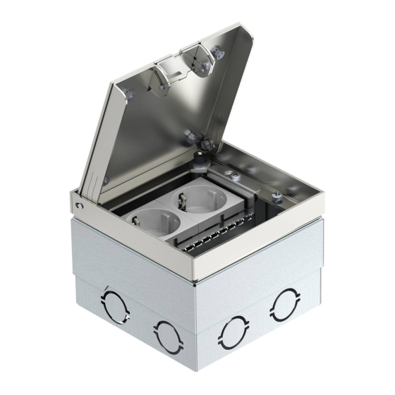
    FR Instructions de montage Description du produit Figure : Boîtier de sol carré pour revêtement de sol net- toyé à sec sur chape et pour systèmes au sol . Boîtier de montage avec sortie de câble dans le couvercle rabattable pour exécution à câbles . Avec huit ouvertures d‘insertion pré- découpées pour tubes d‘installation (M25) . Cadre réglable à l‘aide de quatre supports de nivellement sur le rebord supérieur du revête- ment de sol . La profondeur d‘encastrement mi- nimale est de 95 mm, la plage de réglage +20 mm .
  • Page 34 Principe de montage Figure : Boîtier de sol Garniture d‘étanchéité, par ex . Silicone Revêtement de sol Chape (ou système au sol) Sol en béton Montage du boîtier de sol O uvrir le couvercle rabattable, par ex . à l‘aide d‘un tournevis plat . R etirer et stocker le cas échéant le support de montage en desserrant les vis de fixation . T racer les trous de perçage sur un sol en béton et percer .
  • Page 35 I nsérer de 5 mm max . les tubes d‘installation M25 (accessoires) dans le boîtier de sol et les fixer au sol à l‘extérieur . Conseil : Si la pose de la chape s‘effectue im- médiatement après, installer le support de mon- tage dans le boîtier de sol sans le fixer, simple- ment à des fins de stockage . Couler la chape F ermer le couvercle rabattable et mettre le couvercle de montage en place . Remarque : Nous recommandons une pose de la chape sans couche d‘isolant . Pour réduire la transmission du bruit, une couche d‘isolant peut être utilisée ; elle réduit toutefois l‘ancrage du boîtier de sol dans la chape .
  • Page 36: Réalisation De L'installation Électrique

    Réalisation de l‘installation électrique R etirer le couvercle de montage et ouvrir le couvercle rabattable . M ettre les décharges de traction en place devant les tubes d‘installation . I nsérer les câbles de raccordement jusqu‘à env . 150–200 mm de profondeur et fixer en pressant la décharge de traction . É léments de raccordement module 45 (par ex . prises) dans le support de montage et procéder au raccordement comme indiqué...
  • Page 37: Élimination

    Mise en place et nivellement du revête- ment de sol M ettre le revêtement de sol en place, en conservant un joint de dilatation de 1 à 5 mm par rapport au boîtier de sol . e t Niveler l‘arête supérieure du boîtier de sol et la mettre à fleur par rapport à l‘arête supérieure du revêtement de sol . Pour ce faire, dévisser de manière appropriée les quatre supports de nivellement à l‘aide d‘un tournevis plat .
  • Page 38: Caractéristiques Techniques

    Caractéristiques techniques Type UDHome2 BV N° d'article 7427 019 Dimensions 125 x 125 x 95 mm L x l x H Plage de réglage + 20 mm Poids env . 1,5 kg Ouvertures 8 x 25 mm (M25) Profondeur de montage 95 mm minimale Hauteur de montage max . (chape/système 115 mm au sol + revêtement de sol) Classe de protection pour sortie de câble IP 40 / IP 20 fermée/ouverte Type de nettoyage du sécher sol selon EN 50085-2-2 Plage de température 5 – 60 °C compatible avec le Type de prise module 45...
  • Page 39: It Istruzioni Di Montaggio

    Istruzioni di montaggio Descrizione del prodotto Figura : Modulo apparecchi quadrato per rivestimenti dei pavimenti lavati a secco su massetti e per pavi- menti di sistema . Alloggiamento da incasso con uscita per fili nel coperchio ribaltabile per l‘uscita dei cavi . Con otto aperture passacavo preforate per i tubi di installazione (M25) . Il telaio è regolabile, grazie ai quattro supporti di livellamento , al bordo superiore del rivesti- mento del pavimento . La profondità di montag- gio minima è 95 mm, il campo di livellamento +20 mm .
  • Page 40 Principio di installazione Figura : Modulo apparecchi Sigillatura dei giunti, ad es . Silicone Rivestimento del pavimento Massetto (o pavimento di sistema) Pavimento in calcestruzzo Montaggio del modulo apparecchi A prire il coperchio ribaltabile ad es . con un cacciavite a taglio . R imuovere e conservare il supporto di mon- taggio svitando le viti di fissaggio . T racciare ed eseguire i fori sul pavimento in calcestruzzo . S e necessario rimuovere i passaggi per tubi perforati ad es . con un cacciavite a taglio . M ontare il modulo apparecchi con il materia- le di fissaggio adatto (ad es . tasselli e viti) al pavimento in calcestruzzo .
  • Page 41 Suggerimento: se viene poi realizzata la posa del massetto, allora inserire il supporto di mon- taggio all‘interno del modulo apparecchi . Posa massetto C hiudere il coperchio ribaltabile e applicare la copertura di montaggio . Nota: si consiglia di posare il massetto senza strato di separazione supplementare . Per ridurre la trasmissione del suono può essere utilizzato uno strato di separazione, ma questo riduce l‘ancoraggio saldo del modulo apparecchi al massetto . P osare il massetto a livello con il bordo su- periore della copertura di montaggio e adat- tarlo al modulo apparecchi .
  • Page 42 Esecuzione dell‘installazione elettrica R imuovere la copertura di montaggio e apri- re il coperchio ribaltabile . A pplicare gli scarichi di trazione prima dei tubi di installazione . I nserire i cavi di collegamento per circa 150– 200 mm e fissarli premendo insieme lo sca- rico di trazione . A gganciare gli elementi di collegamento del Modul 45 (ad es . inserti della presa) nel sup- porto di montaggio e collegarli come mostra- to . Collegare anche il collegamento PE del modulo apparecchi . P iegare verso il basso di 90° il diaframma di separazione (1.), inserire il supporto di mon- taggio nel modulo apparecchi (2.) e serrare (3.) .
  • Page 43: Smaltimento

    Applicazione e livellamento del rivesti- mento del pavimento A pplicare il rivestimento del pavimento, nel fare ciò lasciare un giunto di dilatazione di 1–5 mm dal modulo apparecchi . e livellare il bordo superiore del modulo apparecchi al bordo superiore del rivesti- mento del pavimento . Allo scopo svitare con un cacciavite a taglio i quattro supporti di li- vellamento . R iempire il giunto di dilatazione intorno al modulo apparecchi con un materiale flessibi- le adatto (ad es . silicone) .
  • Page 44: Dati Tecnici

    Dati tecnici Tipo UDHome2 BV Numero articolo 7427 019 Dimensioni 125 x 125 x 95 mm Lu . x La . x Al . Area di livellamento + 20 mm Peso ca . 1,5 kg Aperture passacavo 8 x 25 mm (M25) Profondità di montaggio 95 mm minima Altezza di montaggio max . (massetto/pavimento di 115 mm sistema + rivestimento del pavimento) Classe di protezione con uscita per fili chiusa/ IP 40 / IP 20 aperta Tipo di pulizia del pavimento secondo asciutto EN 50085-2-2 Range di temperatura di 5 – 60 °C lavoro compatibile con il Tipo di presa Modul 45...
  • Page 45: Ru Монтажная Инструкция

    RU Монтажная инструкция Описание изделия Рис . : Квадратный лючок для напольного покрытия с видом ухода «насухую» на стяжке и си- стемных полах . Встроенный корпус с выпу- ском кабеля в откидной крышке для вы- вода кабеля . С восемью заготовленными отверстиями с заглушками для ввода мон- тажных труб (M25) . Рамка выравнивается по верхней кромке напольного покрытия с помощью четырех регулируемых по высоте...
  • Page 46 Принцип монтажа Рис . : Лючок Уплотнение шва, например, силикон Напольное покрытие Стяжка (или системный пол) Бетонный пол Монтаж лючка О ткройте откидную крышку, например, с помощью отвертки . П ри необходимости выньте и отложите в сторону монтажную рамку, вывернув крепежные винты . Р азметьте отверстия на бетонном полу и просверлите их . В зависимости от потребности удалите, например, с помощью шлицевой отверт- ки, заглушки из отверстий для ввода труб . С...
  • Page 47 В ведите монтажные трубы M25 (принад- лежности) в лючок на расстояние не бо- лее 5 мм и закрепите их с внешней сторо- ны к полу . Рекомендация: если далее предстоит нане- сение стяжки, вставьте незакрепленную монтажную рамку в лючок, чтобы не поте- рять его . Нанесение стяжки З акройте откидную крышку и установите сверху монтажную накладку . Указание: рекомендуется наносить стяжку...
  • Page 48 Выполнение монтажа электропроводки С нимите монтажную накладку и откройте откидную крышку . В ставьте разгрузку от натяжения перед монтажными трубами . В ведите соединительные кабели прибл . на 150—200 мм и зафиксируйте их сжати- ем разгрузки от натяжения . С оединительные элементы для модуля 45 (например, розетки) введите до щелчка в монтажную рамку и подключите как по- казано . Присоедините клемму защитного провода лючка . С огните пластину перегородки под углом 90° вниз (1.), вставьте монтажную рамку в лючок (2.) и закрепите винтом (3.) .
  • Page 49 Укладка и выравнивание напольного покрытия У ложите напольное покрытие, оставив расширительный шов рядом с лючком шириной 1—5 мм . и выровняйте верхнюю кромку лючка заподлицо с верхней кромкой напольного покрытия . Для этого соответственно вы- верните шлицевой отверткой четыре ре- гулируемые по высоте опоры . З аполните расширительный шов вокруг лючка соответствующим эластичным ма- териалом (например, силиконом) .
  • Page 50: Технические Характеристики

    Технические характеристики Тип UDHome2 BV Артикульный номер 7427 019 Габаритные размеры 125 x 125 x 95 мм Д x Ш x В Диапазон 20 мм регулирования Вес ок . 1,5 кг Отверстия для ввода 8 x 25 мм (M25) Минимальная 95 мм монтажная глубина Максимальная монтажная высота 115 мм (стяжка/системный пол + напольное покрытие) Степень защиты при закрытом/открытом IP 40 / IP 20 выпуске кабеля Вид ухода за полами сухой согласно EN 50085-2-2 Диапазон рабочей 5 — 60 °C температуры совместим с Тип розетки модулем 45...
  • Page 52 OBO Bettermann Holding GmbH & Co. KG P. O. Box 1120 58694 Menden GERMANY Customer Service: Tel.: +49 2373 89 - 17 00 Fax.: +49 2373 89 -12 38 info@obo.de www.obo-bettermann.com...

Table des Matières