LiftMaster LMTBUL Mode D'emploi
Table des Matières
Les langues disponibles
Les langues disponibles
Liens rapides
Introduction
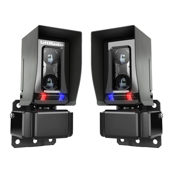
The LiftMaster
®
Photoelectric Sensors provide
non-contact monitored entrapment protection. For
use with LiftMaster
®
UL Listed gate operators. The
sensors are UL recognized components and meet UL
325 requirements. Monitored external entrapment
protection devices MUST be installed at each
Entrapment Zone. Refer to gate operator manual for
compatibility with LMTBUL sensor.
Specifi cations
Max Range: 90 ft. (27.4 m)
Sensor Dimensions with Hood: 2.29" W x 3.72" H x
2.76" D
Cable Length: 10 ft. (3 m)
Operating Temperature: -40˚C to 65˚C (-40˚F to
149˚F)
Outdoor Rating: Nema 4X
Heater: Thermostatically controlled, NOT
recommended for solar applications
To prevent possible SERIOUS INJURY or DEATH from a closing gate or door:
•
Read and follow ALL instructions.
•
Be sure to DISCONNECT ALL POWER to the operator BEFORE installing the photoelectric sensors.
•
The gate or door MUST be in the fully opened or closed position BEFORE installing the LiftMaster
Monitored Entrapment Protection device.
•
Correctly connect and align the photoelectric sensor.
•
Install the photoelectric sensor so that the center of the sensor window is NO HIGHER than 4-1/2"
(11.4 cm) above the fl oor for door operators and 26" (66 cm) above grade for gate operators.
•
Monitored external entrapment protection devices MUST be installed per the operator installation
manual at each Entrapment Zone.
•
The sensors MUST be mounted vertically.
•
Test the gate operator and ALL photoelectric sensors monthly. Replace ANY damaged devices.
•
SAVE THESE INSTRUCTIONS.
WARNING: This product can expose you to chemicals including lead, which are known
to the State of California to cause cancer or birth defects or other reproductive harm.
For more information go to www.P65Warnings.ca.gov.
MONITORED THROUGH BEAM
PHOTOELECTRIC SENSOR
Input Voltage:
Sensor: Black/red wires 6.8 VDC, 20mA
Heater: Green/white wires 10-40VDC or 8-28 VAC,
4 watts max., 170mA per pair @ 24 VDC/VAC,
340mA per pair @ 12 VDC/VAC
Model LMTBUL
®
Table des Matières

Manuels Connexes pour LiftMaster LMTBUL


Sommaire des Matières pour LiftMaster LMTBUL
-
Page 6: Capteur Photoélectrique Àfaisceau Continu Surveillé
S’assurer de DÉBRANCHER L’ALIMENTATION à l’actionneur AVANT d’installer le capteur à cellule photoélectrique. • La barrière ou la porte DOIT être en position complètement ouverte ou complètement fermée AVANT d’installer le dispositif de protection surveillé contre le piégeage LiftMaster ® • Raccorder et aligner correctement le capteur à cellule photoélectrique. -
Page 7: Inventaire De La Boîte
Inventaire de la boîte Outils nécessaires • Émetteur avec capot et support • Vis à frein-fi let 10-32x1 po (4) • Tournevis à tête cruciforme • Réfl ecteur avec capot et • Vis M3 (2) • Douille de 7/16 po support •... -
Page 8: Câblage Du Capteur
Câblage Câblage du capteur (fi ls rouge et noir) : Câbler les capteurs à cellule photoélectrique (fi ls rouge [+] et noir [-]) aux entrées appropriées sur l’actionneur ou la carte d’extension, comme montré. Câblage de l’appareil de chauffage (fi ls vert et blanc) : •... -
Page 9: Réinitialisation Du Mode De Portée
Alignement Remettre l’alimentation à l’actionneur. Aligner les capteurs. Les DEL sur le RÉCEPTEUR indiquent l’alignement. La DEL rouge indique un capteur désaligné ou obstrué. La DEL bleue indique la puissance du signal. Un clignotement lent indique un signal faible. Un clignotement rapide indique un signal plus fort. La DEL bleue allumée en continu indique un alignement optimal. -
Page 10: Dépannage
LMEHUL : Le capot allongé du capteur photoélectrique améliore encore plus la fi abilité dans des conditions météorologiques extrêmes. APOW1 : Transformateur enfi chable Garantie LiftMaster ® garantit à l’acheteur initial de ce produit que celui-ci est exempt de tout défaut matériel et/ou de fabrication pendant une période de deux ans suivant la date d’achat. - Page 16 © 2018, LiftMaster All Rights Reserved Tous droits réservés 01-39359B Todos los Derechos Reservados LiftMaster.com...