GE VE700AM Manuel D'installation
Table des Matières
Les langues disponibles
Les langues disponibles
GE
Security
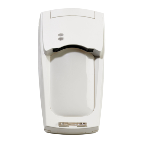
Vector Enhanced Motion Sensor VE700AM
Installation instructions
EN
pages 8-19
Rivelatore di movimento Vector Enhanced
VE700AM
IT
Istruzioni per l'installazione
pagg. 20-32
Capteur de mouvement à vecteur amélioré
VE700AM
FR
Manuel d'installation
pages 33-45
Bewegingsdetector met vector VE700AM
Installatie-handleiding
NL
Pagina's 46-58
Bewegungsmelder VE700AM mit
Vektorauswertung
DE
Installationsanweisungen
Seiten 59-72
Chapitres
Table des Matières

Manuels Connexes pour GE VE700AM


Sommaire des Matières pour GE VE700AM
- Page 1 Security Vector Enhanced Motion Sensor VE700AM Installation instructions pages 8-19 Rivelatore di movimento Vector Enhanced VE700AM Istruzioni per l’installazione pagg. 20-32 Capteur de mouvement à vecteur amélioré VE700AM Manuel d’installation pages 33-45 Bewegingsdetector met vector VE700AM Installatie-handleiding Pagina’s 46-58 Bewegungsmelder VE700AM mit...
- Page 3 1 2 3 4 5 6 7 8 9 10 11 12 DIN 7996 (3.5 mm x 35 mm) - 1 -...
- Page 5 (ex-factory) AM DIP switches COM port PIR DIP switches - 3 -...
- Page 7 VE700AM (ex-factory) 3 sec. 3 sec. VE700AM Right Left Night ---- Alarm Chime Alarm Night Chime Alarm ---- Alarm - 5 -...
- Page 8 VE700AM 1.8-3.0 m (5.9-9.8 ft.) - 6 -...
- Page 9 2.3 m (7.5 ft) 20 m (65.6 ft) 60 m (197 ft) SB01 1 2 3 4 5 6 7 8 9 10 11 Control panel 1 2 3 4 5 6 7 8 9 10 11 ST400 - 7 -...
- Page 35 Instructions d’installation 1. Introduction .................... 33 2. Instructions d’installation ............... 33 3. Montage du détecteur ................34 4. Réglage du détecteur ................35 5. Test de l’anti-masque ................39 6. Alignement du faisceau et test de marche du détecteur ...... 39 7.
-
Page 36: Montage Du Détecteur
3. Montage du détecteur Relevez l’insert personnalisé et retirez la vis qui s’y trouve (figure , étapes 1 et 2). A l’aide d’un tournevis, ouvrez délicatement le détecteur en faisant levier (figure , étapes 3 et 4). Retirez la partie interne (figure Fixez la base au mur à... -
Page 37: Réglage Du Détecteur
4. Réglage du détecteur Il faut redémarrer le détecteur (le remettre sous tension) après avoir modifié les paramètres ou les schémas de détection. Cavaliers (figure J1 : Sensibilité d’IRP Le délai de déclenchement de l’alarme (vitesse de l’algorithme de décision) dépend directement de la sensibilité... -
Page 38: Commutateur Dip 1 : Polarité De Tension De Contrôle
Activée haut Activée bas Commutateur DIP 1 : Polarité de tension de contrôle Activé : “Activée haut” (par positif) fournit la logique GE Security standard avec une sortie active pour activer les entrées test de marche et jour/nuit. Désactivé : “Activée bas” fournit une sortie non active pour activer les entrées test de marche et jour/nuit. -
Page 39: Commutateur Dip 4 : Voyants
Commutateur DIP 2 : Carillon (figure Le détecteur distingue la direction de l’intrus pendant la journée. Désactivez cette option en désactivant le carillon du détecteur. Lorsque le carillon est activé, le détecteur déclenche l’alarme dès lors qu’un intrus traverse les rideaux, de droite à... -
Page 40: Sensibilité D'anti-Masque
12 secondes. 3. Réinitialisation des sorties AM/PT Le détecteur VE700AM réinitialise une alarme AM une fois qu’il est sûr que la cause de l’alarme AM a été supprimée. Si le circuit AM ne peut pas revenir à ses niveaux de référence d’origine, soit le détecteur est toujours masqué, soit il a été... -
Page 41: Test De L'anti-Masque
5. Test de l’anti-masque Séquence d’initialisation AM : Lorsque le détecteur VE700AM est alimenté, le circuit AM attend que le cache du détecteur soit monté de manière appropriée. Une fois le cache monté, le circuit AM surveille le boîtier et la zone environnante et stocke les niveaux des signaux reçus comme niveaux de... -
Page 42: Sans L'outil D'alignement (Fig. J, Cache Arrière)
B. Sans l’outil d’alignement (fig. j, cache arrière) Insérez les œillères du miroir pour assurer le fonctionnement du détecteur en mode rideau simple. Placez J2 et patientez jusqu’à l’extinction des voyants lumineux. Déplacez-vous dans le champ de vision du détecteur, à une vitesse normale (sans pause) et à... -
Page 43: Identification De L'état Du Détecteur Via Les Voyants
7. Identification de l’état du détecteur via les voyants A) Indication des voyants Tableau 3 : Indication du voyant = Allumage continu = Clignotement normal (1 Hz) = Clignotement rapide (4 Hz) Etat du Voyant Voyant Réinitialisation détecteur jaune rouge Unité... -
Page 44: Verrouillage
A) Verrouillage Lorsque vous utilisez plusieurs détecteurs dans une seule boucle, câblez les entrées jour/nuit et test de marche, comme indiqué ci-après (à la figure Nuit Jour/nuit Jour Test de marche On (Activé) Off (Désactivé) Centrale Détecteurs B) Activation/désactivation à distance du voyant du test de marche (figure Mettez le détecteur en mode jour et activez l’état test de marche. -
Page 45: Masquage Des Rideaux (Figure D)
AM. B : Ils sont causés par l’auto-test et le test à distance. Test à distance : Ce test vous permet de tester le VE700AM depuis la centrale. Activez-le à partir de la borne 12. Le détecteur VE700AM active le relais d’alarme si le résultat du test est positif et le relais AM si le résultat... -
Page 46: Problème Technique
Auto-test : Etat PIR (IRP)* : Borne 12 : 8 hr. 8 hr. AM* : Relais d’alarme : VE700AM 8 hr. 8 hr. 3 sec. Relais AM : Relais AM : VE700AM non OK * Démarre 1 heure après l’installation Problème technique :... -
Page 47: Spécifications Techniques
Mode de localisation de rideau (MLR) : Fonction du détecteur permettant d’identifier précisément les extrémités des rideaux. Mode jour : Le détecteur ne génère aucun signal ou message d’alarme lorsqu’il détecte une personne dans son champ de vision. Mode nuit : Le détecteur génère un signal ou message d’alarme lorsqu’il détecte une personne dans son champ de vision. - Page 75 - 73 -...