Publicité
Publicité
Table des Matières

Manuels Connexes pour ENERMAX LIQMAX III ARGB


Sommaire des Matières pour ENERMAX LIQMAX III ARGB
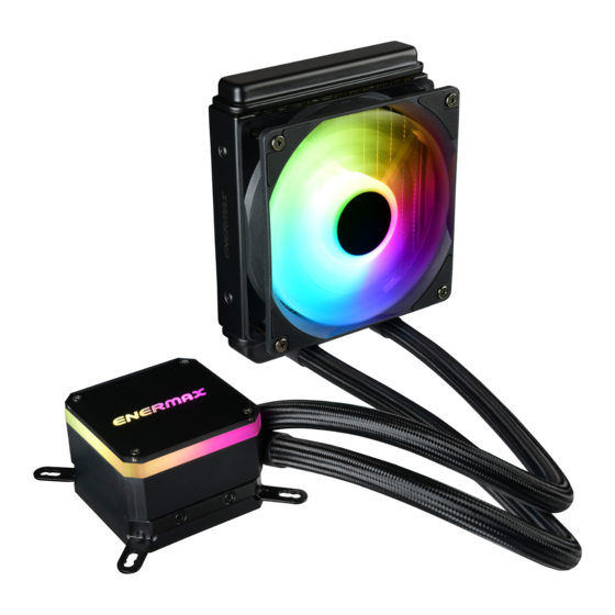
- Page 1 120|240|280|360 mm...
-
Page 2: Table Des Matières
Index Limited Warranty ........................Warranty & Support informa�on for Australia ................. Specifica�on ..........................Part List ............................. Intel® Installa�on ........................AMD® Installa�on ........................- 1 -... -
Page 3: Limited Warranty
This ENERMAX Technology Corpora�on product is warranted to be free from defects in material and workmanship for a period of two (2) years from the date of purchase. ENERMAX Technology Corpora�on agrees to repair or replace the product, at its own op�on and at no charge, if, during the warranty period, it is returned to nearest ENERMAX Technology Corpora�on subsidiary/agent with all shipping charges prepaid and if inspec�on reveals that... -
Page 4: Warranty & Support Informa�On For Australia
Web Site: h�p://www.enermax.com E-mail: enermax@enermax.com.tw This ENERMAX liquid cooler is warranted to be free from defects in material and workmanship for period stats in two(2) years. ENERMAX Technology Corpora�on agrees to repair or replace the product, at its own op�on and at no charge, if during the warranty perod, it is returned to nearest ENERMAX Technology Corpora�on subsidiary/agent with all shipping charges prepaid... -
Page 5: Specifica�On
Specifica�on ELC-LMT360-ARGB Model ELC-LMT120-ARGB ELC-LMT240-ARGB ELC-LMT280-ARGB ELC-LMT360-W-ARGB Intel® LGA 2066/2011-3/2011/1366/1200/1156/1155/1151/1150 CPU Socket AMD® AM4/AM3+/AM3/AM2+/AM2/FM2+/FM2/FM1 Material Copper Base with Aluminum Radiator Bearing Ceramic Bearing MTBF 50,000 hrs Motor Speed 3100 RPM ± 10% Pump Rated Voltage 12 V 0.4 A Rated Current - *or 0.53A if not connected to 4 pin RGB connector (5V/D/-/G) Pump Water... - Page 6 LIQMAX III ARGB 120 - Part List Cooler x 1 Back Plate x 1 Fan x 1 Posi�on Screw x 4 Square Spacer x 1 Stand-off x 4 Case Screw x 8 Fan Screw x 8 Intel LGA 2011/2066 Spring Screw x 4...
- Page 7 LIQMAX III ARGB 240 - Part List Cooler x 1 Back Plate x 1 Fan x 2 Posi�on Screw x 4 Square Spacer x 1 Stand-off x 4 Case Screw x 8 Fan Screw x 8 Intel LGA 2011/2066 Spring Screw x 4...
- Page 8 LIQMAX III ARGB 280 - Part List Cooler x 1 Fan x 2 Back Plate x 1 Posi�on Screw x 4 Square Spacer x 1 Case Screw x 8 Fan Screw x 8 Stand-off x 4 Intel Clip x 1...
- Page 9 LIQMAX III ARGB 360 - Part List Cooler x 1 Fan x 3 Back Plate x 1 Posi�on Screw x 4 Square Spacer x 1 Case Screw x 12 Fan Screw x 12 Stand-off x 4 Intel Clip x 1...
-
Page 10: Intel Installa�On
Intel Installa�on - 9 -... - Page 11 Intel Installa�on Step 1 A�ach the fan and the radiator to the chassis. Schrauben Sie den Lü�er und den Radiator am Gehäuse fest. Fixez le ven�lateur et le radiateur sur le châssis. Fissare la ventola e il radiatore al case. Fijar el ven�lador y el radiador a la caja.
- Page 12 Intel Installa�on Step 2 Install the Intel clip to the pump. Mon�eren Sie die Intel-Halterung an der Pumpe. Installez le clip Intel à la pompe. Installare il fermaglio Intel sulla pompa. Instalar la pinza Intel en la bomba. Zainstaluj do pompki zaczep Intel. 安裝Intel支架於泵浦...
- Page 13 Intel Installa�on Step 3 *LGA1200/1150/1151/1156/1366 LGA1366 LGA1200 /115X Insert the posi�on screws into the proper holes on the back plate. Then use the washers to fix the posi�on screws. 《 If your CPU pla�orm is Intel LGA2011/2011-3/2066, please skip to step 4-2》 Drehen Sie die Montageschrauben in die zu Ihrem Sockel passende Bohrung in der Backplate wie abgebildet an.《Wenn Sie einen LGA2011/2011-3/2066-Sockel verwenden, gehen Sie bi�e zu Schri�...
- Page 14 Intel Installa�on Step 4-1 *LGA1200/1150/1151/1156/1366 Install the Intel back plate on to the back of motherboard; fix the back plate with the stand-off. Befes�gen Sie die Intel-Backplate auf der Mainboard-Rückseite. Schrauben Sie die Backplate mit den zugehörigen Abstandshaltern fest. Installez la plaque arrière Intel sous la carte-mère à l’aide des vis du support. Installare la piastra posteriore Intel nella parte posteriore della scheda madre;...
- Page 15 Intel Installa�on Step 4-2 *Intel LGA 2011/2011-3/2066 Tighten the Intel LGA2011/2011-3/2066 screw to the motherboard. Schrauben Sie die Backplate mit den passenden LGA2011/2011-3/2066-Abstandshaltern am Mainboard fest. Serrez la vis du support Intel LGA2011/2011-3/2066 à la carte-mère. Fissare i montan� per Intel LGA2011/2011-3/2066 alla scheda madre. Fije los tornillos de pilar para Intel LGA2011/2011-3/2066 a la placa madre.
- Page 16 Intel Installa�on Step 5 Apply the thermal grease evenly on the CPU surface. Verteilen Sie gleichmäßig eine dünne Schicht Wärmeleitpaste auf der CPU-Oberfläche. Appliquez une couche uniforme de pâte thermique sur la surface du CPU. Applicare in modo uniforme la pasta termica sulla superficie della CPU. Aplicar de forma uniforme la pasta térmica en la superficie de la CPU.
- Page 17 Intel Installa�on Step 6 Remove the protect film from the cold-plate. En�ernen Sie die Schutzfolie von der Kühlpla�e der Pumpe. Re�rez le film protecteur de la plaque-froide. Rimuovere la pellicola di protezione dalla piastra di raffreddamento. Quite la película de protección del bloque de refrigeración. Zdjąć...
- Page 18 Intel Installa�on Step 7 Place the pump on the CPU and �ghten the spring screws un�l all four corners are secured. Platzieren Sie die Pumpe auf der CPU und drehen Sie die Federschrauben fest bis alle vier Seiten fixiert sind. Placez la pompe sur le CPU et serrez les vis à...
- Page 19 Intel Installa�on Step 8 Pump Pump 3 pin 4 pin Connect the pump power connector to the motherboard. No�ce: If you recognize that your mainboard's CPU fan or PWM sockets do not provide enough voltage to power the pump, please use the included 4-pin Molex adaptor and connect the pump directly to your PSU. Schließen Sie den Stromstecker der Pumpe am Mainboard an.
- Page 20 Intel Installa�on Step 9 PWM Y cable 4 pin Connect the fan connector to the motherboard. Schließen Sie den 4-Pin-PWM-Stecker des Lü�ers am Mainboard an. Branchez le connecteur du ven�lateur à la carte-mère. Collegare il conne�ore della ventola alla scheda madre. Conecte el conector del ven�lador a la placa madre.
-
Page 21: Amd Installa�On
AMD Installa�on - 20 -... - Page 22 AMD Installa�on Step 1 A�ach the fan and the radiator to the chassis. Schrauben Sie den Lü�er und den Radiator am Gehäuse fest. Fixez le ven�lateur et le radiateur sur le châssis. Fissare la ventola e il radiatore al case. Fijar el ven�lador y el radiador a la caja.
- Page 23 AMD Installa�on Step 2 Install the AMD clip to the pump Mon�eren Sie die AMD-Halterung an der Pumpe Installez le clip AMD à la pompe Installare il fermaglio AMD sulla pompa Instalar la pinza AMD en la bomba. Zainstaluj do pompki zaczep AMD 安裝AMD支架於泵浦...
- Page 24 AMD Installa�on Step 3 AM3/AM2 Insert the posi�on screw into the appropriate hole on the back plate for your CPU socket. Place the square spacer on the central hole of the back plate. Drehen Sie die Montageschrauben in die zu Ihrem Sockel passende Bohrung in der Backplate.
- Page 25 AMD Installa�on Step 4 Install the AMD back plate on to the back of motherboard; fix the back plate with the stand-off. Befes�gen Sie die AMD-Backplate auf der Mainboard-Rückseite. Schrauben Sie die Backplate mit den zugehörigen Abstandshaltern fest. Installez la plaque arrière AMD sous la carte-mère à l’aide des vis du support. Installare la piastra posteriore AMD nella parte posteriore della scheda madre;...
- Page 26 AMD Installa�on Step 5 Apply the thermal grease evenly on the CPU surface. Verteilen Sie gleichmäßig eine dünne Schicht Wärmeleitpaste auf der CPU-Oberfläche. Appliquez une couche uniforme de pâte thermique sur la surface du CPU. Applicare in modo uniforme la pasta termica sulla superficie della CPU. Aplicar de forma uniforme la pasta térmica en la superficie de la CPU.
- Page 27 AMD Installa�on Step 6 Remove the protect film from the cold-plate. En�ernen Sie die Schutzfolie von der Kühlpla�e der Pumpe. Re�rez le film protecteur de la plaque-froide. Rimuovere la pellicola di protezione dalla piastra di raffreddamento. Quite la película de protección del bloque de refrigeración. Zdjąć...
- Page 28 AMD Installa�on Step 7 Place the pump on the CPU and �ghten the spring screws un�l all four corners are secured. Platzieren Sie die Pumpe auf der CPU und drehen Sie die Federschrauben fest bis alle vier Seiten fixiert sind. Placez la pompe sur le CPU et serrez les vis à...
- Page 29 AMD Installa�on Step 8 Pump Pump 3 pin 4 pin Connect the pump power connector to the motherboard. No�ce: If you recognize that your mainboard's CPU fan or PWM sockets do not provide enough voltage to power the pump, please use the included 4-pin Molex adaptor and connect the pump directly to your PSU. Schließen Sie den Stromstecker der Pumpe am Mainboard an.
- Page 30 AMD Installa�on Step 9 PWM Y cable 4 pin Connect the fan connector to the motherboard. Schließen Sie den 4-Pin-PWM-Stecker des Lü�ers am Mainboard an. Branchez le connecteur du ven�lateur à la carte-mère. Collegare il conne�ore della ventola alla scheda madre. Conecte el conector del ven�lador a la placa madre.
-
Page 31: Motherboard Sync
Motherboard Sync - 30 -... - Page 32 Motherboard Sync Addressable RGB Header +5V D LIQMAX III ARGB 120 LIQMAX III ARGB 240 LIQMAX III ARGB 280 to the motherboard. +5V D LIQMAX III ARGB 360 Connect the sync cable to a supported motherboard with ARGB header Verbinden Sie das Sync-Kabel mit einem kompa�blen Motherboard mit ARGB-Header.
-
Page 33: Rgb Control Box
RGB Control Box For non-addressable RGB motherboard - 32 -... - Page 34 RGB Control Box When you install the cooler onto the motherboard, please connect the RGB Sync cable to the water block, and then connect the power connectors to RGB control box. Meanwhile, connect the SATA power cable to PC power supply SATA connector. Wenn Sie den Kühler auf dem Motherboard installieren, schließen Sie bi�e das RGB-Sync-Kabel an den Wasserblock und dann die Stromanschlüsse an die RGB-Steuerbox an.
- Page 35 RGB Control Box 120mm 240mm/ 280mm/ 360mm 280mm/360mm 280mm/360mm - 34 -...
- Page 36 RGB Control Box Light effect mode (GREEN) Effect up/down Mode The 4 LED colors indicate the different modes: GREEN (Light Effect), RED (Effect Speed), BLUE (Brightness), YELLOW (Auto-run). 1. Press “M” un�l you reach the Light Effect Mode (GREEN). 2. To change the effect, press the ▲ or ▼ bu�on. 3.
- Page 37 RGB Control Box Les 4 couleurs des diodes indiquent les différents modes: VERT (Effets lumineux), ROUGE (Vitesse), BLEU (Luminosité) et JAUNE (Mode Auto). 1. Appuyez sur “M” jusqu’à ce que vous a�eigniez le mode Effets lumineux (diode verte). 2. Pour faire varier l’effet, appuyez sur▲ou▼. 3.
- Page 38 RGB Control Box Znaczenie 4 kolorów światła LED: ZIELONE (tryb efektu światła), CZERWONE (tryb szybkości), NIEBIESKIE (tryb podświetlenia), ŻÓŁTE (automatyczne uruchamianie). 1. Naciśnij "M", aby przełączyć efekt, szybkość zmiany światła, podświetlenie i automatyczne uruchamianie. 2. W celu zmiany koloru, naciśnij przycisk▲lub▼, aby uruchomić jeden z 10, wstępnie ustawionych efektów światła.
- Page 39 RGB Control Box 緑色 (ライト効果) 、 赤色 (エフェク トスピード) 、 青色 (明るさ) 、 黄色 (オートラン) の つの カ ラーは、 異なるモードを示します。 1. ライトエフェク トモード (緑色) になるまで " "を押します。 2. エフェク トを変更するには、 ▲または▼ボタンを押します。 種のプリセッ トライト効果 : 1) レーシング - レインボー (デフォルト) 2) 呼吸 – レインボー 3) フラッシュレインボー...
- Page 40 RGB Control Box Effect Speed Mode (RED) Speed up/down Mode 1. Press “M” un�l you reach the Effect Speed Mode (RED). 2. To change the effect speed, press the▲or▼bu�on. 1. Drücken Sie "M", bis Sie den Effektgeschwindigkeitsmodus (ROT) erreichen. 2. Um die Effektgeschwindigkeit zu ändern, drücken Sie die Taste▲oder▼. 1.
- Page 41 RGB Control Box Brightness mode (BLUE) Brightness up/down Mode 1. Press “M” un�l you reach the Brightness Mode (BLUE). 2. To adjust the brightness, press the▲or▼bu�on. 3. Press “M” in any mode for 3 seconds to turn-off the light. Press “M” again to turn on the light and con�nue with the previous effect.
- Page 42 RGB Control Box 1.明暗模式下,指示燈亮藍燈;此時按▲▼鍵可調整燈的明暗度 2.按 鍵可切換到其他模式 3.任一模式下長按3秒 鍵會關機;關機狀態下再按 鍵會開機並回到上次關機前的燈型模式 1.明暗模式下,指示灯亮蓝灯;此时按▲▼键可调整灯的明暗度 2.按 M 键可切换到其它模式 3.任一模式下长按3秒M键会关机;关机状态下再按M键会开机并回到上次关机前的灯型模式 1. 明るさモード (青) に達するまで " "を押します。 2. 明るさを調整するには、 ▲または▼ボタンを押します。 3. 任意のモードで 「 」 を 秒間押して、 ライトを消灯させます。 " "をもう一度押してライトを点 灯させ、 前のエフェク トを続行します。 1.“ ”버튼을 눌러 밝기변경 모드(파랑)를 선택하세요. 2.▲혹은▼버튼을...
- Page 43 © 2020 ENERMAX TECHNOLOGY CORPORATION. All right reserved. Specifica�ons are subject to change without prior no�ce. Some trademarks may be claimed as the property of others. Mar. 2020...