Table des Matières

Publicité

Les langues disponibles

Les langues disponibles

Liens rapides

Installation and maintenance manual
SINGLE LEVER CONTROL
B 310
R
UK
F
I
page. 2
pag. 21
page. 41
PARTNER
(Dr./Dis./Des. n° 25975/a 13/02/2015)

Publicité

Table des Matières
loading

Sommaire des Matières pour Ultraflex B 310

  • Page 1 Installation and maintenance manual SINGLE LEVER CONTROL B 310 page. 2 pag. 21 page. 41 PARTNER (Dr./Dis./Des. n° 25975/a 13/02/2015)
  • Page 2 Products for pleasure boats are constantly tested to check their conformity with the 2013/53/EU. "ULTRAFLEX has over 80 years of experience in the marine industry and is a world leader in the production of mechanical, hydraulic and electronic steering systems, control boxes and steering wheels for any kind of pleasure, fishing or commercial boats.
  • Page 3: Table Des Matières

    ULTRAFLEX Installation and maintenance manual TABLE OF CONTENTS USE OF THE MANUAL AND SYMBOLS USED....................4 INFORMATION LETTER............................5 WARRANTY..........................5 SECTION 1 - PRODUCT DESCRIPTION PRODUCT DESCRIPTION AND RECOMMENDED USE............6 DIMENSIONS.........................6 SECTION 2 - TRANSPORT GENERAL WARNINGS..........................7 PACKAGING CONTENTS...........................7 SECTION 3 - INSTALLATION NECESSARY TOOLS..........................8...
  • Page 4: Use Of The Manual And Symbols Used

    ULTRAFLEX Installation and maintenance manual USE OF THE MANUAL AND SYMBOLS USED THE INSTALLATION AND MAINTENANCE MANUAL is the document accompanying the product from its sale to its replacement and discharge. The manual is an important part of the product itself.
  • Page 5: Information Letter

    We remind you that only marked steering systems must be used on the boats marked . We inform you that the ULTRAFLEX warranty is null if some ULTRAFLEX components are installed on a steering system together with products of other brands. page 5...
  • Page 6: Product Description And Recommended Use

    The B310 single control lever is also equipped with trim. The B310 control unit can use the following ULTRAFLEX cables: - C2 - C7 - C8 - MACHZero - C14 - MACH14 (no connection kit...
  • Page 7: Transport

    ULTRAFLEX Installation and maintenance manual 2 TRANSPORT 2.1 General warnings The product weight with its packaging is 2.5kg (5.5 pounds) and so it can be handled manually. WARNING The staff in charge of handling must operate with protective gloves and safety shoes.
  • Page 8: Necessary Tools

    ULTRAFLEX Installation and maintenance manual 3 INSTALLATION 3.1 Necessary tools Punch Drill Phillips Open end Pliers Ø 6 - 6,5 mm screwdriver wrench [0,23"-0,25"] or 10mm[0,395”] screwdriver 3.2 Throttle reversing THE B310 CONTROL IS SUPPLIED IF THE THROTTLE LEVER OF...
  • Page 9: C2-C7-C8-Machzero Cable Installation

    ULTRAFLEX Installation and maintenance manual Turn the lever (6) 180 degrees as shown in the drawing. Reinstall spring (5), tube (4), washer (3) and screw (2). WARNING - Correct control operation depends on precise adjustment of the shift gear travel.
  • Page 10: Throttle Cable Connection With Push Mechanism

    ULTRAFLEX Installation and maintenance manual Insert the pivot pin (11) into one of the two holes of the rocker Insert nut (10) on the arm (1) (inner hole for a 67 mm (2,64") and outer hole for a 78 cable end and screw the mm (3,07") travel) then attach with the screw (12).
  • Page 11: Throttle Cable Connection With Pull Mechanism

    ULTRAFLEX Installation and maintenance manual Attach casing Insert nut (10) on fastener (O) with the cable end and screws (L) to screw the terminal prevent cable (H). Tighten nut (10). disengagement Connect the terminal from control to the throttle lever box.
  • Page 12: C14 And Mach14 Cable Installation

    ULTRAFLEX Installation and maintenance manual 3.4 C14 and MACH14 cable installation 3.4.1 Shift cable connection Connect the terminal of the cable (H) to pivot pin (11) located on the inner hole of the rocker arm (67 mm (2.64") travel), then attach with snap ring (E).
  • Page 13: Throttle Cable Connection With Pull Mechanism

    ULTRAFLEX Installation and maintenance manual 3.4.3 Throttle cable connection with pull mechanism Connect the terminal of the cable to the throttle lever (16), then attach with snap ring (E). Insert the cross cylinder of cable sheath end into seat (g).
  • Page 14: Control Box Positioning

    1.2. The mechanism with the cables connected must be installed inside the boat bulkhead. WARNING Avoid bending the cables too tight (Minimum radius: 200 mm (8"). We recommend using ULTRAFLEX cables. After choosing the right position, drill to insert the control box using the suitable template.
  • Page 15: Assembling B310 Lever-Mechanism

    ULTRAFLEX Installation and maintenance manual 3.7 Assembling B310 lever-mechanism Insert bezel (A1) on flange (3) by pressing it. Insert the electric cable of lever (A2) through the hole of the cover. Attach the lever unit using screw (M) and press on cap (N).
  • Page 16: Trim Electrical Connections

    ULTRAFLEX Installation and maintenance manual 3.9 Trim electrical connections Carry out the electrical connections of the cables coming from the lever by following the diagrams below according to the motor used. NOTICE These controls work only on the motors shown below. Controls marked with (*) need an additional TILT switch.
  • Page 17 ULTRAFLEX Installation and maintenance manual SWITCH TECHNICAL DATA: Resistive load: 6 Ohm 12V Inductive load: 2A 12V NOTICE In case of high inductive load, it is advisable to use a supporting relay to protect the switch. page 17 of 63...
  • Page 18: Lever Use

    ULTRAFLEX Installation and maintenance manual 4 LEVER USE 4.1 Lever use The lever travel includes two movements: in the first phase the shift gear is enabled; in the second one the throttle is enabled. If the lever is in forward position, the boat moves forward; if the lever is in backward position, the boat goes in reverse.
  • Page 19: Safety Warnings

    5.1 Safety rules during installation and use RESPECT STRICTLY the following safety rules. ULTRAFLEX declines all responsibility in case the user does not follow these rules and it is not responsible for negligence during the use of the system. DANGER - DO NOT PUT HANDS BETWEEN THE MOVING PARTS.
  • Page 20: Extraordinary Maintenance

    ULTRAFLEX Installation and maintenance manual 6.2 Extraordinary maintenance Technical assistance For any information or for assistance with unusual applications please contact our technical support personnel (See paragraph "Information letter"). 7 DISMANTLING 7.1 Dismantling When for any reason, the system is put out of service, it is necessary to follow some rules in order to respect the environment.
  • Page 21 Manuale di installazione e manutenzione COMANDO MONOLEVA B 310 SOCIO...
  • Page 22 Gentile Cliente, La ringraziamo per aver scelto un prodotto ULTRAFLEX. ULTRAFLEX è da anni un punto di riferimento nei sistemi di guida nel settore della nautica da diporto e professionale. Da sempre la produzione ULTRAFLEX è sinonimo di grande affidabilità e sicurezza.
  • Page 23 ULTRAFLEX Manuale di installazione e manutenzione INDICE GENERALE USO DEL MANUALE E SIMBOLOGIA IMPIEGATA....................24 LETTERA INFORMATIVA............................25 GARANZIA..........................25 SEZIONE 1 - DESCRIZIONE DEL PRODOTTO DESCRIZIONE DEL PRODOTTO E RACCOMANDAZIONI SULL'UTILIZZO..........26 DIMENSIONI.........................26 SEZIONE 2 - TRASPORTO AVVERTENZE GENERALI..........................27 CONTENUTO IMBALLO..........................27 SEZIONE 3 - INSTALLAZIONE UTENSILI NECESSARI..........................28...
  • Page 24: Uso Del Manuale E Simbologia Impiegata

    ULTRAFLEX Manuale di installazione e manutenzione USO DEL MANUALE E SIMBOLOGIA IMPIEGATA Il MANUALE DI INSTALLAZIONE E MANUTENZIONE è il documento che accompagna il prodotto dal momento della sua vendita fino alla sua sostituzione e smaltimento. Risulta cioè essere parte integrante dello stesso.
  • Page 25: Lettera Informativa

    GARANZIA ULTRAFLEX garantisce che i suoi prodotti sono costruiti a regola d'arte e che sono privi di difetti di fabbricazione e di materiali. Questa garanzia è valida per un periodo di due anni decorrenti dalla data di fabbricazione dei prodotti ad eccezione dei casi in cui questi siano installati ed usati su barche da lavoro o comunque su barche ad utilizzo commerciale, nel qual caso la garanzia è...
  • Page 26: Descrizione Del Prodotto E Raccomandazioni Sull'utilizzo

    Dispone inoltre dell'azionamento "trim". Il comando monoleva B310 può utilizzare i seguenti cavi ULTRAFLEX: - C2 - C7 - C8 - MACHZero - C14 - MACH14 senza kit di connes- sione;...
  • Page 27: Avvertenze Generali

    ULTRAFLEX Manuale di installazione e manutenzione 2 TRASPORTO 2.1 Avvertenze generali Il peso del prodotto con il suo imballo è di circa 2,5Kg (5,5 pounds) e quindi la sua movimentazione può essere effettuata manualmente. AVVERTENZA Il personale addetto alla manipolazione del carico deve operare con guanti protettivi e scarpe antinfortunistiche.
  • Page 28: Utensili Necessari

    ULTRAFLEX Manuale di installazione e manutenzione 3 INSTALLAZIONE 3.1 Utensili necessari Punzone Trapano Cacciavite a Chiave Pinza Ø 6 - 6,5 mm stella esagonale [0,23"-0,25"] o 10mm[0,395”] cacciavite a croce 3.2 Inversione del senso di comando acceleratore IL COMANDO B310 VIENE FOR-...
  • Page 29: Montaggio Dei Cavi C2-C7-C8-Machzero

    ULTRAFLEX Manuale di installazione e manutenzione Ruotare la levetta (6) di 180° come indicato in figura. Reinstallare la molla (5), il tubetto (4), la rondella (3) e la vite (2). AVVERTENZA - Il corretto funzionamento del comando dipende dall'esatta regolazione della corsa dell'invertitore.
  • Page 30: Collegamento Del Cavo Acceleratore Con Meccanismo Che Lavora In Compressione

    ULTRAFLEX Manuale di installazione e manutenzione Inserire il perno con piastrina (11) in uno dei fori del Inserire il dado (10) sul bilanciere (1) (usare il foro interno per una corsa di 67 mm (2.64") terminale del cavo e avvi- ed il foro esterno per una corsa di 78 mm (3.07") e fissarlo con la...
  • Page 31: Collegamento Del Cavo Acceleratore Con Meccanismo Che Lavora In Trazione

    ULTRAFLEX Manuale di installazione e manutenzione Fissare Inserire il dado (10) fermaguaina (O) sul terminale del cavo con le viti (L) per e avvitare il puntale (H). impedire Stringere il dado (10). sfilamento dei Agganciare il puntale al cavi dal coman-...
  • Page 32: Montaggio Dei Cavi C14 E Mach14

    ULTRAFLEX Manuale di installazione e manutenzione 3.4 Montaggio dei cavi C14 e MACH14 3.4.1 Collegamento del cavo invertitore Collegare il puntale del cavo (H) al perno con piastri- na (11) posizionato sul foro interno (corsa di 67 mm (2.64") del bilanciere, fermandolo con l'anello di ritegno (E).
  • Page 33: Collegamento Del Cavo Acceleratore Con Meccanismo Che Lavora In Trazione

    ULTRAFLEX Manuale di installazione e manutenzione 3.4.3 Collegamento del cavo acceleratore con meccanismo che lavora in trazione Collegare il puntale del cavo al perno della levetta (16), fermandolo con l'anello di ritegno (E). Inserire il cilindretto del terminale guaina nella sede (g).
  • Page 34: Posizionamento Della Scatola Di Comando

    AVVERTENZA Evitare che i cavi siano sottoposti a curvature troppo strette (Raggio minimo: 200 mm - 8"-). Si raccomanda l'uso di cavi ULTRAFLEX. Dopo aver stabilito la collocazione ap- propriata, eseguire la foratura necessa- ria all'inserimento della scatola di coman- do con l'ausilio dell'apposita dima.
  • Page 35: Montaggio Gruppo Leva-Meccanismo B310

    ULTRAFLEX Manuale di installazione e manutenzione 3.7 Montaggio gruppo leva-meccanismo B310 Inserire a pressione il copriviti (A1) sulla flangia (3). Inserire il cavo elettri- co della leva (A2) attraver- foro della mascherina. Posizionare il gruppo leva e fissarlo con la vite (M).
  • Page 36: Collegamenti Elettrici Trim

    ULTRAFLEX Manuale di installazione e manutenzione 3.9 Collegamenti elettrici trim Effettuare i collegamenti elettrici dei cavi provenienti dalla leva seguendo gli schemi di seguito riportati in funzione del motore utilizzato. NOTA Questi comandi funzionano solo sui motori sotto elencati. Quelli indicati con (*) necessitano di un ulte- riore interruttore per il TILT.
  • Page 37 ULTRAFLEX Manuale di installazione e manutenzione DATI TECNICI DELLO SWITCH: Carico resistivo: 6 Ohm 12V Carico induttivo: 2A 12V NOTA In caso di alto carico induttivo, si suggerisce di utilizzare un relay di appoggio per salvaguardare lo switch. pag. 37...
  • Page 38: Uso Della Leva

    ULTRAFLEX Manuale di installazione e manutenzione 4 USO DELLA LEVA 4.1 Uso della leva La corsa della leva è divisa in due movimenti: nella prima fase si aziona l'invertitore; nella seconda fase l'acceleratore. Portando la leva in avanti si ottiene l'avanzamento dell'imbarcazione, mentre all'in- dietro si procede in retromarcia.
  • Page 39: Avvertenze Di Sicurezza

    RISPETTATE TASSATIVAMENTE le precauzioni ed i criteri di sicurezza indicati qui di seguito. ULTRAFLEX declina ogni responsabilità nel caso in cui l'utilizzatore non li osservi, così come non è respon- sabile per qualsiasi tipo di negligenza che venga commessa durante l'utilizzo del sistema.
  • Page 40: Manutenzione Straordinaria

    ULTRAFLEX Manuale di installazione e manutenzione PERICOLO L'allentamento o la separazione dei dadi di fissaggio può causare, oltre al malfunzionamento del comando monoleva, danni a persone e a cose. - Periodicamente controllare che non vi sia corrosione sulle parti metalliche dei terminali del cavo e abrasioni sulla guaina.
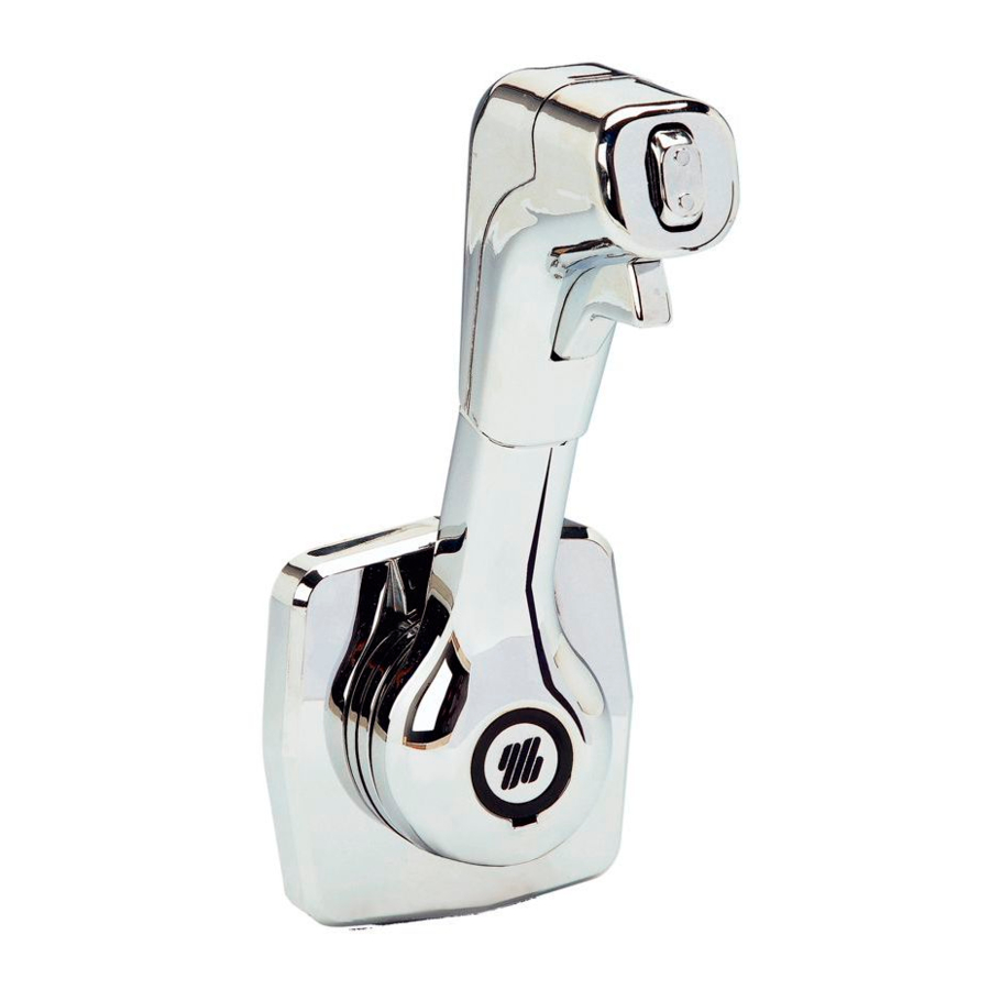
  • Page 41 Manuel d'installation et d'entretien COMMANDE MONO-LEVIER B 310 SOCIO...
  • Page 42 Tous les produits ULTRAFLEX sont conçus et fabriqués pour assurer toujours les performances les meilleures. Pour assurer votre sécurité et pour maintenir toujours un niveau de qualité élevé ULTRAFLEX ne garantit ses produits que si les pièces de rechange originales sont utilisées (voir annexe "Application Spare Parts").
  • Page 43 ULTRAFLEX Manuel d'installation et d'entretien INDEX GENERAL EMPLOI DU MANUEL ET SYMBOLES UTILISES....................44 LETTRE D'INFORMATION............................45 GARANTIE..........................45 SECTION 1 - DESCRIPTION DU PRODUIT DESCRIPTION DU PRODUIT ET RECOMMANDATIONS D'EMPLOI..........46 DIMENSIONS.........................46 SECTION 2 - TRANSPORT AVERTISSEMENTS GENERAUX.........................47 CONTENU EMBALLAGE...........................47 SECTION 3 - INSTALLATION OUTILS NECESSAIRES..........................48...
  • Page 44: Emploi Du Manuel Et Symboles Utilises

    ULTRAFLEX Manuel d'installation et d'entretien EMPLOI DU MANUEL ET SYMBOLES UTILISES Le MANUEL D'INSTALLATION ET D'ENTRETIEN est le document qui accompagne le produit de sa vente jusqu'à son remplacement et sa démolition. C'est donc une partie fondamentale du manuel lui-même.
  • Page 45: Lettre D'information

    à des fautes d'impression, contenues dans le manuel. Bien que les caractéristiques principales du type de produit décrit ne changent pas, la Société ULTRAFLEX se réserve le droit de modifier les descriptions, les details et les illustrations qu'elle jugera nécessaires afin de l'améliorer, soit pour des exigences de caractère constructif ou commercial, dans n'importe quel moment et sans être obligé...
  • Page 46: Description Du Produit Et Recommandations D'emploi

    ULTRAFLEX Manuel d'installation et d'entretien 1 DESCRIPTION DU PRODUIT 1.1 Description du produit et recommandations d'emploi La commande mono-levier doit être assemblée sur la cloison de B310 tribord ou de gauche la plus proche du poste de guidage du bateau.
  • Page 47: Avertissements Generaux

    ULTRAFLEX Manuel d'installation et d'entretien 2 TRANSPORT 2.1 Avertissements généraux Le poids du produit avec son emballage est d'environ 2,5Kg (5,5 livres), il peut donc être manutentionné manuellement. AVERTISSEMENT Le personnel chargé de la manipulation de l'installation doit porter des gants de protection et des chaussures de sécurité.
  • Page 48: Outils Necessaires

    ULTRAFLEX Manuel d'installation et d'entretien 3 INSTALLATION 3.1 Outils nécessaires Poinçon Perceuse Tournevis étoile Clé Pince Ø 6 - 6,5 mm [0,23"- hexagonale 0,25"] ou tournevis 10mm[0,395”] cruciforme 3.2 Inversion du sens de commande de l'accélérateur LA COMMANDE B310 EST...
  • Page 49: Montage Des Cables C2-C7-C8-Machzero

    ULTRAFLEX Manuel d'installation et d'entretien Touner le levier (6) de 180° comme indiqué dans la figure. Remonter le ressort (5), le tube (4), la rondelle (3) et la vis (2). AVERTISSEMENT - Le fonctionnement correct de la commande dépend du réglage précis de l'inverseur.
  • Page 50: Branchement Du Cable Accelerateur Avec Mecanisme Qui Travaille En Compression

    ULTRAFLEX Manuel d'installation et d'entretien Insérer le pivot avec plaque (11) dans un des trous du culbuteur Insérer l'écrou (10) sur (1) (trou interne pour une course de 67 mm (2,64") trou externe la partie terminale du câble pour une course de 78 mm (3,07") et le fixer avec la vis (12).
  • Page 51: Insérer L'écrou

    ULTRAFLEX Manuel d'installation et d'entretien Fixer l'arrête- Insérer l'écrou gaine (O) avec les (10) sur la partie ter- pour minale du câble et empêcher que les visser l'extrémité (H). câbles sortent de Serrer l'écrou (10). la commande. A c c r o c h e r l'extrémité...
  • Page 52: Montage Des Cables C14 Et Mach14

    ULTRAFLEX Manuel d'installation et d'entretien 3.4 Montage des câbles C14 et MACH14 3.4.1 Branchement du câble inverseur Connecter l'extrémité du câble (H) au pivot avec plaque (11) positionné sur le trou interne (course de 67 mm (2.64") du culbuteur en le fixant avec la bague d'arrêt (E).
  • Page 53: Branchement Du Cable Accelerateur Avec Mecanisme Qui Travaille En Traction

    ULTRAFLEX Manuel d'installation et d'entretien 3.4.3 Branchement du câble accélérateur avec mécanisme qui travaille en traction Connecter l'extrémité du câble au pivot du levier (16), en la fixant avec la bague d'arrêt (E). Insérer le petit cylindre du terminal de la gaine dans le logement (g).
  • Page 54: Positionnement De La Boite De Commande

    1.2. Le mécanisme, avec les câbles connectés, doit être assemblé de la partie intérieure de la cloison du bateau. AVERTISSEMENT Eviter que les câbles soient soumis à des courbures trop étroites (Rayon minimum: 200 mm (8"). On recommande d'utiliser de câbles ULTRAFLEX. Après avoir choisi la position appropriée, effectuer perçage...
  • Page 55: Assemblage Groupe Levier-Mecanisme B310

    ULTRAFLEX Manuel d'installation et d'entretien 3.7 Assemblage groupe levier-mécanisme B310 Insérer à pression le couvre-vis (A1) dans la bride (3). Insérer le câble électrique du levier (A2) à travers le trou de la couverture. Positionner le groupe levier et le fixer à l'aide de la vis (M).
  • Page 56: Branchements Trim

    ULTRAFLEX Manuel d'installation et d'entretien 3.9 Branchements trim Brancher les câbles sortant du levier en suivant les schémas indiqués ci-dessous selon le moteur utilisé. NOTE Ces commandes fonctionnent seulement sur les moteurs listés ci-dessous. Les moteurs indiqués avec (*) nécessitent d'un autre interrupteur pour le TILT. Se référer au schéma de circuit relatif au moteur qui est en train d'être utilisé.
  • Page 57 ULTRAFLEX Manuel d'installation et d'entretien HAUT N.B.: CONNECTER CONDUCTEUR DE MAS- I N T E R R U P T E U R HAUT D ' I N C L I N A I S O N SE MARRON B A S...
  • Page 58: Emploi Du Levier

    ULTRAFLEX Manuel d'installation et d'entretien 4 EMPLOI DU LEVIER 4.1 Emploi du levier La course du levier est divisée en deux mouvements: dans la première phase l'inverseur est activé; dans la deuxième phase l'accélérateur est activé. En positionnant en avant le levier le bateau avance, en le positionnant en arrière le bateau va en marche arrière.
  • Page 59: Avertissements De Securite

    RESPECTER RIGOUREUSEMENT les précautions et les critères de sécurité indiqués ci-dessous. La Société ULTRAFLEX décline toute responsabilité au cas où l'usager ne les respecterait pas; elle n'est pas non plus responsable pour tout type de négligence commise pendant l'emploi du système.
  • Page 60: Entretien Extraordinaire

    ULTRAFLEX Manuel d'installation et d'entretien DANGER Le desserrage ou la séparation des écrous de fixation peut causer non seulement le mauvais fonctionnement de la commande mono-levier, mais aussi des dommages aux personnes et aux choses. - Périodiquement vérifier l'absence de corrosion sur les parties métalliques des extrémités des câbles et d'abrasions sur la gaine.
  • Page 61 ULTRAFLEX Manuel d'installation et d'entretien NOTES page 61 de 63 COMMANDE MONO-LEVIER B310...
  • Page 62 ULTRAFLEX Manuel d'installation et d'entretien NOTES page 62 de 63 - COMMANDE MONO-LEVIER B310...
  • Page 63 ULTRAFLEX Manuel d'installation et d'entretien NOTES page 63 de 63 COMMANDE MONO-LEVIER B310...
  • Page 64 ULTRAFLEX S.p.A. 16015 Casella (Genova) Italia - Via Crose, 2...
  • Page 65: Gabarit De Perçage Pour Commande Mono-Levier B310

    Drilling template for B310 single lever control Dima di foratura per comando monoleva B310 Gabarit de perçage pour commande mono-levier B310 Ø 5,6mm (0,22 TYP) 76,2 +0 -0,25 (3”+0 -0,01”) ULTRAFLEX SOCIO...

Table des Matières