Télécharger Imprimer la page

Publicité

Les langues disponibles

Les langues disponibles

Liens rapides

Preface
X99S SLI PLUS
Motherboard
G52-78851X7

Publicité

loading

Sommaire des Matières pour MSI X99S SLI PLUS

  • Page 1 Preface X99S SLI PLUS Motherboard G52-78851X7...
  • Page 2: Trademarks

    Copyright Notice The material in this document is the intellectual property of MICRO-STAR INTERNATIONAL. We take every care in the preparation of this document, but no guarantee is given as to the correctness of its contents. Our products are under continual improvement and we reserve the right to make changes without notice.
  • Page 3: Smartphone Application

    If a problem arises with your system and no solution can be obtained from the user’s manual, please contact your place of purchase or local distributor. Alternatively, please try the following help resources for further guidance. Visit the MSI website for technical guide, BIOS updates, driver updates, and other information: http://www.msi.com/support/ Contact our technical staff at: http://register.msi.com/...
  • Page 4: Safety Instructions

    Safety Instructions ■ Always read the safety instructions carefully. ■ Keep this User’s Manual for future reference. ■ Keep this equipment away from humidity. ■ Lay this equipment on a reliable flat surface before setting it up. ■ The openings on the enclosure are for air convection hence protects the equipment from overheating.
  • Page 5: Fcc-B Radio Frequency Interference Statement

    FCC-B Radio Frequency Interference Statement This equipment has been tested and found to comply with the limits for a Class B digital device, pursuant to Part 15 of the FCC Rules. These limits are designed to provide reasonable protection against harmful interference in a residential installation. This equipment generates, uses and can radiate radio frequency energy and, if not installed and used in accordance with the instructions, may cause harmful interference to radio communications.
  • Page 6: Radiation Exposure Statement

    Radiation Exposure Statement This equipment complies with FCC radiation exposure limits set forth for an uncontrolled environment. This equipment and its antenna should be installed and operated with minimum distance 20 cm between the radiator and your body. This equipment and its antenna must not be co-located or operating in conjunction with any other antenna or transmitter.
  • Page 7: Battery Information

    Replace only with the same or equivalent type recommended by the manufacturer. Chemical Substances Information In compliance with chemical substances regulations, such as the EU REACH Regulation (Regulation EC No. 1907/2006 of the European Parliament and the Council), MSI provides the information of chemical substances in products at: http://www.msi.com/html/popup/csr/evmtprtt_pcm.html Preface...
  • Page 8: Weee (Waste Electrical And Electronic Equipment) Statement

    MSI will comply with the product take back requirements at the end of life of MSI-branded products that are sold into the EU. You can return these products to local collection points.
  • Page 9 MSI će poštovati zahtev o preuzimanju ovakvih proizvoda kojima je istekao vek trajanja, koji imaju MSI oznaku i koji su prodati u EU. Ove proizvode možete vratiti na lokalnim mestima za prikupljanje.
  • Page 10 MSI si adeguerà a tale Direttiva ritirando tutti i prodotti marchiati MSI che sono stati venduti all’interno dell’Unione Europea alla fine del loro ciclo di vita.
  • Page 11 2008 № 1057. Việt Nam RoHS Kể từ ngày 01/12/2012, tất cả các sản phẩm do công ty MSI sản xuất tuân thủ Thông tư số 30/2011/TT-BCT quy định tạm thời về giới hạn hàm lượng cho phép của một số...
  • Page 12: Table Des Matières

    CONTENTS ▍ English ...................... En-1 Motherboard Specifications ................En-2 Block Diagram ....................En-5 Connectors Quick Guide ..................En-6 Back Panel Quick Guide ..................En-8 CPU (Central Processing Unit) ................En-10 Memory ......................En-14 Mounting Screw Holes ..................En-17 Power Supply ....................En-18 Expansion Slots ....................En-19 Internal Connectors ..................En-20 Button .......................En-27 Jumper ......................En-29 Switch .......................En-30...
  • Page 13 Français ..................... Fr-1 Spécifications ......................Fr-2 Block Diagram .....................Fr-5 Guide Rapide Des Connecteurs .................Fr-6 Guide rapide du panneau arrière ................Fr-8 Processeur : CPU .....................Fr-10 Mémoire ......................Fr-14 Trous Taraudés de Montage ................Fr-17 Connecteurs d’alimentation ................Fr-18 Emplacements d’extension ................Fr-19 Connecteurs internes ..................Fr-20 Boutons ......................Fr-27 Cavaliers ......................Fr-29 Interrupteur ......................Fr-30 Pilotes et Utilitaires ....................Fr-31...
  • Page 14 Installation/ Установка ................A-1 CPU ........................A-2 Memory/ Speicher/ Mémoire/ Памяти ..............A-4 Motherboard/ Carte mère/ Материнские платы ..........A-5 Power Connector/ ATX-Stromanshcluss/ Connecteurs d'alimentation/ Pазъема питания ........................A-7 SATA HDD ......................A-9 M.2 ........................A-10 Front Panel Connector/ Frontpanel Anschluss/ Connecteur panneau avant/ Pазъемов передней панели ................A-11 Peripheral Connector/ Peripheriestecker/ Connecteur périphérique/ Периферийных...
  • Page 15: English

    English Thank you for choosing the X99S SLI PLUS Series (MS-7885 v1.X) ATX motherboard. The X99S SLI PLUS Series motherboards are based on Intel ® X99 chipset for optimal system efficiency. Designed to fit the advanced Intel ® LGA2011-3 processor, the X99S SLI PLUS Series motherboards deliver a...
  • Page 16: Motherboard Specifications

    USB 2.0 connectors) ■ ASMedia ASM1042AE - 2x USB 3.0 ports on the back panel ■ VIA VL805 - 4x USB 3.0 ports on the back panel * Internal JUSB1 connector supports MSI Super Charger. Audio ■ Realtek ALC892 Codec ®...
  • Page 17 Back Panel ■ 1x PS/2 keyboard/ mouse combo port ■ 2x USB 2.0 ports Connectors ■ 1x Clear CMOS button ■ 8x USB 3.0 ports ■ 1x LAN (RJ45) port ■ 1x Optical S/PDIF OUT connector ■ 5x OFC audio jacks Internal ■...
  • Page 18 Software ■ Drivers ■ MSI - Command Center - Live Update 6 - Smart Utilities - Super Charger - Fast Boot - ECO Center ■ Norton Internet Security Solution ■ Intel Extreme Tuning Utility Form ■ ATX Form Factor ■ 12 in. x 9.6 in. (30.5 cm x 24.4 cm)
  • Page 19: Block Diagram

    Block Diagram 4 Channel DDR4 Memory Haswell-E Processor LGA2011-3 CPU Switch PCIe x1 slot PCI Express Bus (for 40 lanes CPU only) Switch PCI Express Bus Intel I218 Gigabit LAN DMI 2.0 1 x M.2 Switch 1 x SATA Express PCIe x1 slot 10 x SATA 6Gb/s (2 ports reserved for SATA Express)
  • Page 20: Connectors Quick Guide

    Connectors Quick Guide JPWR2 CPUFAN2 DIMM1 DIMM8 SYSFAN1 DIMM2 DIMM7 DIMM3 DIMM6 CPU Socket DIMM4 DIMM5 CPUFAN1 JBAT1 Back Panel JPWR1 JUSB1 JCI1 PCI_E1 JUSB2 PCI_E2 SATA1_2 PCI_E3 SATA3_4 PCI_E4 SATA7_8 M2_1 PCI_E5 SATA9_10 JTPM1 PCI_E6 BIOS1 SYSFAN2 JAUD1 SYSFAN3 SATA6 SATA5 JSLOW1...
  • Page 21 Connectors Reference Guide Port Name Port Type Page Back Panel En-8 BIOS1 Multi-BIOS Switch En-30 CPUFAN1~2,SYSFAN1~3 Fan Power Connectors En-22 LGA2011-3 CPU Socket En-11 DIMM1~8 Memory Slots En-14 JAUD1 Front Panel Audio Connector En-26 JBAT1 Clear CMOS Jumper En-29 JCI1 Chassis Intrusion Connector En-25 JFP1, JFP2...
  • Page 22: Back Panel Quick Guide

    Back Panel Quick Guide LAN Port PS/2 Port CS-Out Line-In/ SS-Out USB 3.0 Port USB 3.0 Port Clear CMOS RS-Out Line-Out Button USB 2.0 Port USB 3.0 Port USB 3.0 Port Optical S/PDIF-Out ▶ PS/2 Port A PS/2 DIN connector is for a PS/2 mouse/keyboard.
  • Page 23 ▶ LAN Port The standard RJ-45 LAN jack is for connecting to a Local Area Network (LAN). LED Status Description No link Link/ Activity LED Yellow Linked LINK/ACT SPEED Blinking Data activity 10 Mbps connection Speed LED Green 100 Mbps connection Orange 1 Gbps connection ▶...
  • Page 24: Cpu (Central Processing Unit)

    This motherboard is designed to support overclocking. Before attempting to overclock, please make sure that all other system components can tolerate overclocking. Any attempt to operate beyond product specifications is not recommend. MSI does not guarantee the damages or risks caused by inadequate operation beyond product specifications.
  • Page 25: Cpu & Heatsink Installation

    CPU & Heatsink Installation When installing a CPU, always remember to install a CPU heatsink. A CPU heatsink is necessary to prevent overheating and maintain system stability. Follow the steps below to ensure correct CPU and heatsink installation. Wrong installation can damage both the CPU and the motherboard.
  • Page 26 5. Line up the CPU to fit the CPU socket. Be sure to hold the CPU by the base with the metal contacts facing downward. The alignment keys on the CPU will line up with the edges of the CPU socket to ensure a correct fit. 6.
  • Page 27 9. Evenly spread a thin layer of thermal paste (or thermal tape) on the top of the CPU. This will help in heat dissipation and prevent CPU overheating. 10. Locate the CPU fan connector on the mainboard. CPUFAN1 Thermal paste 11.
  • Page 28: Memory

    Memory These DIMM slots are used for installing memory modules. DIMM1 DIMM2 DIMM3 DIMM4 DIMM8 DIMM7 DIMM6 DIMM5 SATA9_10 SATA7_8 SATA3_4 SATA1_2 Video Demonstration Watch the video to learn how to install memory. http://youtu.be/T03aDrJPyQs Up to Quad-Channel mode This mainboard supports up to four memory channels. Two DIMM slots provide a single channel.
  • Page 29 Suggestions for Multi-Channel mode population rule Dual-Channel mode Installed DIMMs Diagram (2 memory modules) DIMM1 DIMM2 DIMM3 DIMM4 DIMM1, DIMM5 DIMM8 DIMM7 DIMM6 DIMM5 Triple-Channel mode Installed DIMMs Diagram (3 memory modules) DIMM1 DIMM2 DIMM3 DIMM4 DIMM1, DIMM3, DIMM5 DIMM8 DIMM7 DIMM6 DIMM5...
  • Page 30 Quad-Channel mode Installed DIMMs Diagram (6 memory modules) DIMM1 DIMM2 DIMM3 DIMM4 DIMM1, DIMM2, DIMM3, DIMM5, DIMM6, DIMM7 DIMM8 DIMM7 DIMM6 DIMM5 Installed DIMMs Diagram (8 memory modules) DIMM1 DIMM2 DIMM3 DIMM1, DIMM2, DIMM4 DIMM3, DIMM4, DIMM5, DIMM6, DIMM8 DIMM7, DIMM8 DIMM7 DIMM6 DIMM5...
  • Page 31: Mounting Screw Holes

    Mounting Screw Holes When installing the motherboard, first install the necessary mounting stands required for an motherboard on the mounting plate in your computer case. If there is an I/O back plate that came with the computer case, please replace it with the I/O backplate that came with the motherboard package.
  • Page 32: Power Supply

    Power Supply Video Demonstration Watch the video to learn how to install power supply connectors. http://youtu.be/gkDYyR_83I4 JPWR1~2: ATX Power Connectors These connectors allow you to connect an ATX power supply. To connect the ATX power supply, align the power supply cable with the connector and firmly press the cable into the connector.
  • Page 33: Pci_E1~6: Pcie Expansion Slots

    Expansion Slots This motherboard contains numerous slots for expansion cards, such as discrete graphics or audio cards. PCI_E1~6: PCIe Expansion Slots The PCIe slot supports the PCIe interface expansion card. PCIe 3.0 x16 Slot PCIe 2.0 x1 Slot PCIe Bandwidth Table ■...
  • Page 34: Internal Connectors

    Internal Connectors SATA1~10: SATA Connectors This connector is a high-speed SATA interface port. Each connector can connect to one SATA device. SATA devices include disk drives (HDD), solid state drives (SSD), and optical drives (CD/ DVD/ Blu-Ray). Video Demonstration Watch the video to learn how to Install SATA HDD. http://youtu.be/RZsMpqxythc SATA2 SATA1...
  • Page 35 SATA_EX1: SATA Express Connector The SATA Express, a new high performance storage interface, supports to connect 1 SATA Express device with up to 10 Gb/s transfer rate. Connects the SATA Express device to this 3-in-1 connector by a SATA Express cable. M2_1: M.2 Port The M.2 port supports either M.2 SATA 6Gb/s module or M.2 PCIe module.
  • Page 36 CPUFAN1~2,SYSFAN1~3: Fan Power Connectors The fan power connectors support system cooling fans with +12V. If the motherboard has a System Hardware Monitor chipset on-board, you must use a specially designed fan with a speed sensor to take advantage of the CPU fan control. Remember to connect all system fans.
  • Page 37 JFP1, JFP2: System Panel Connectors These connectors connect to the front panel switches and LEDs. The JFP1 connector is compliant with the Intel Front Panel I/O Connectivity Design Guide. When ® installing the front panel connectors, please use the optional M-Connector to simplify installation.
  • Page 38 • Please only connect one device per USB port to ensure stable charging. • Super-Charger Technology is only available on select MSI motherboard models. Please refer to the MSI website to check if your motherboard has Super-Charger technology. • For iPad, JUSB1 (red mark) can still charge iPad in S3, S4, S5 state.
  • Page 39: Jci1: Chassis Intrusion Connector

    JUSB3~4: USB 2.0 Expansion Connectors This connector is designed for connecting high-speed USB peripherals such as USB HDDs, digital cameras, MP3 players, printers, modems, and many others. Important Note that the VCC and GND pins must be connected correctly to avoid possible damage.
  • Page 40: Jtpm1: Tpm Module Connector

    JAUD1: Front Panel Audio Connector This connector allows you to connect the front audio panel located on your computer case. This connector is compliant with the Intel Front Panel I/O Connectivity Design ® Guide. JTPM1: TPM Module Connector This connector connects to a TPM (Trusted Platform Module). Please refer to the TPM security platform manual for more details and usages.
  • Page 41: Button

    BIOS section of the manual for instructions on how to turn off OC Genie from the BIOS. • The usage of OC Genie is at the user’s own risk. Overclocking is never guaranteed by MSI. • To ensure successfully OC Genie usage, MSI components are recommended. En-27...
  • Page 42 POWER1: Power Button This button is used to turn-on and turn-off the system. Press the button once to turn-on or turn-off the system. RESET1: Reset Button This reset button is used to reset the system. Press the button to reset the system. En-28...
  • Page 43: Jslow1: Slow Mode Booting Jumper

    Jumper JBAT1: Clear CMOS Jumper There is CMOS RAM onboard that is external powered from a battery located on the motherboard to save system configuration data. With the CMOS RAM, the system can automatically boot into the operating system (OS) every time it is turned on. If you want to clear the system configuration, set the jumpers to clear the CMOS RAM.
  • Page 44: Bios1: Multi-Bios Switch

    Preparation: 1. Prepare a bootable USB flash drive. 2. Download the latest BIOS file from the MSI official website at www.msi.com, and then decompress the file. 3. Copy the AFUDE238.exe and the BIOS file to the bootable USB flash drive BIOS recovery steps: 1.
  • Page 45: Drivers And Utilities

    After you install the operating system you will need to install drivers to maximize the performance of the new computer you just built. MSI motherboard comes with a Driver Disc. Drivers allow the computer to utilize your motherboard more efficiently and take advantage of any special features we provide.
  • Page 46: Bios Setup

    "MSI Fast Boot" utility screen. Important • Please be sure to install the “MSI Fast Boot” utility before using it to enter the BIOS setup. • The items under each BIOS category described in this chapter are under continuous update for better system performance. Therefore, the description may be slightly different from the latest BIOS and should be held for reference only.
  • Page 47 Overview After entering BIOS, the following screen is displayed. Temperature monitor My Favorites Language System information Boot device priority bar Virtual OC Genie Button BIOS menu BIOS menu selection selection Menu display ▶ BIOS menu selection The following options are available: ■...
  • Page 48 Enables or disables the OC Genie function by clicking on this button. When enabled, this button will be light. Enabling OC Genie function can automatically overclock with MSI optimized overclocking profile. Important We recommend that you do not to make any modification in OC menu mode and do not to load defaults after enabling the OC Genie function.
  • Page 49 Operation You can control BIOS settings with the mouse and the keyboard. The following table lists and describes the hot keys and the mouse operations. Hot key Mouse Description <↑↓→← > Select Item Move the cursor <Enter> Select Icon/ Field Click/ Double-click the left button <Esc>...
  • Page 50 OC Menu This menu is for advanced users who want to overclock the mainboard. Important • Overclocking your PC manually is only recommended for advanced users. • Overclocking is not guaranteed, and if done improperly, can void your warranty or severely damage your hardware.
  • Page 51 Enables the OC Genie function by virtual button in BIOS or physical button on motherboard. Enabling OC Genie function can automatically overclock the system with MSI optimized overclocking profile. [By BIOS Options] OC Genie function is enabled by clicking the virtual OC Genie button at the top left corner of BIOS setup screen.
  • Page 52 ▶ CPU Base Clock Apply Mode [Auto]* Sets the applying mode for adjusted CPU base clock. [Auto] This setting will be configured automatically by BIOS. [Next Boot] CPU will run the adjusted CPU base clock at next boot. [Immediate] CPU runs the adjusted CPU base clock immediately. [During Boot] CPU will run the adjusted CPU base clock during boot.
  • Page 53 ▶ Memory Fast Boot [Auto] Enables or disables the initiation and training for memory every booting. [Auto] This setting will be configured automatically by BIOS. [Enabled] Memory will completely imitate the archive of first initiation and first training. After that, the memory will not be initialed and trained when booting to accelerate the system booting time.
  • Page 54 ▶ CPU VRM Over Temperature Protection [Enabled] Enables or disables the CPU VRM over-temperature protection. [Enabled] Sets the temperature limit on CPU VRM for over-temperature protection. The CPU frequency may be throttled when CPU temperature over the specified temperature. [Disabled] Disables this function.
  • Page 55 ▶ CPU Core/Ring Voltage Mode [Auto]* Selects the control mode for CPU Core/ Ring voltages. [Auto] This setting will be configured automatically by BIOS. [Adaptive Mode] Sets the adaptive voltage automatically for optimizing the system performance. [Override Mode] Allows you to set the voltage manually. [Offset Mode] Allows you to set the offset voltage and select the voltage offset mode.
  • Page 56 ▶ XXX Voltage [Auto]* (optional) Sets the voltages related to memory/ PCH. If set to "Auto", BIOS will set the voltage automatically or you can set it manually. < Other Setting > ▶ CPU Memory Changed Detect [Enabled]* Enables or disables the system to issue a warning message during boot when the CPU or memory has been replaced.
  • Page 57 ▶ Execute Disable Bit [Enabled] Intel’s Execute Disable Bit functionality can prevent certain classes of malicious “buffer overflow” attacks where worms attempt to execute code to damage the system. It is recommended that keeps this item enabled always. [Enabled] Enables NO-Execution protection to prevent the malicious attacks and worms.
  • Page 58 ▶ Intel C-State [Enabled] C-state is a processor power management technology defined by ACPI. [Auto] This setting will be configured automatically by BIOS. [Enabled] Detects the idle state of system and reduce CPU power consumption accordingly. [Disabled] Disable this function. ▶...
  • Page 59 ▶ Internal VR OVP OCP Protection [Auto] Enables or disables the over-voltage protection and over-current protection for CPU internal VR (Voltage Regulator). [Auto] This setting will be configured automatically by BIOS. [Enabled] Enables the limitation of internal VR for over-voltage protection and over-current protection.
  • Page 61: Deutsch

    Deutsch Danke, dass Sie das X99S SLI PLUS (MS-7885 v1.X) ATX Motherboard gewählt haben. Diese X99S SLI PLUS Motherboard basiert auf dem Intel ® X99 Chipsatz und ermöglicht so ein optimales und effizientes System. Entworfen, um den hochentwickelten Intel LGA2011-3 Prozessor zu ®...
  • Page 62: Spezifikationen

    Anschlussleiste, 4 Anschlüsse stehen durch die internen USB 2.0 Anschlüsse zur Verfügung) ■ ASMedia ASM1042AE - 2x USB 3.0 Anschlüsse an der rückseitigen Anschlussleiste ■ VIA VL805 - 4x USB 3.0 Anschlüsse an der rückseitigen Anschlussleiste * Interner JUSB1 Anschluss unterstützt MSI Super Charger. De-2...
  • Page 63 Audio ■ Realtek ALC892 Codec ® - 7.1-Kanal-HD-Audio - Unterstützt S/PDIF-Ausgang ■ 1x Intel I218 Gigabit LAN Controller Hintere Ein-/ ■ PS/2 Tastatur-/Maus-Combo-Anschluss x1 ■ USB 2.0 Anschlüsse x2 und Ausgänge ■ Clear CMOS Taste x1 ■ USB 3.0 Anschlüsse x8 ■...
  • Page 64 Software ■ Treiber ■ MSI - Kommandozentrale - Live Update 6 - Smart-Funktion - Super Charger - Fast Boot - ECO Center ■ Norton Internet Security Solution ■ Intel Extreme Tuning Utility Formfaktor ■ ATX Formfaktor ■ 12 Zoll x 9,6 Zoll (30,5 cm x 24,4 cm) Weitere CPU Informationen finden Sie unter http://www.msi.com/cpu-support/...
  • Page 65: Blockdiagramm

    Blockdiagramm 4 Channel DDR4 Memory Haswell-E Processor LGA2011-3 CPU Switch PCIe x1 slot PCI Express Bus (for 40 lanes CPU only) Switch PCI Express Bus Intel I218 Gigabit LAN DMI 2.0 1 x M.2 Switch 1 x SATA Express PCIe x1 slot 10 x SATA 6Gb/s (2 ports reserved for SATA Express) X99 PCH...
  • Page 66: Anschlussübersicht

    Anschlussübersicht JPWR2 CPUFAN2 DIMM1 DIMM8 SYSFAN1 DIMM2 DIMM7 DIMM3 DIMM6 CPU Sockel DIMM4 DIMM5 CPUFAN1 JBAT1 Rück- tafel JPWR1 JUSB1 JCI1 PCI_E1 JUSB2 PCI_E2 SATA1_2 PCI_E3 SATA3_4 PCI_E4 SATA7_8 M2_1 PCI_E5 SATA9_10 JTPM1 PCI_E6 BIOS1 SYSFAN2 JAUD1 SYSFAN3 SATA6 SATA5 JSLOW1 JUSB4 JUSB3...
  • Page 67 Übersicht der Motherboard-Anschlüsse Port-Name Port-Typ Seite Rücktafel De-8 BIOS1 Multi-BIOS Schalter De-30 CPUFAN1~2,SYSFAN1~3 Stromanschlüsse für Lüfter De-22 LGA2011-3 CPU Sockel De-11 DIMM1~8 Speichersteckplätze De-14 JAUD1 Audioanschluss des Frontpanels De-26 JBAT1 Steckbrücke zur CMOS-Löschung De-29 JCI1 Gehäusekontaktanschluss De-25 JFP1, JFP2 Systemtafelanschlüsse De-23 JPWR1~2 ATX Stromanschlüsse...
  • Page 68: Rücktafel-Übersicht

    Rücktafel-Übersicht Anschluss PS/2 Anschluss USB 3.0 USB 3.0 CS-Out Line-In/ SS-Out Anschluss Anschluss Clear CMOS RS-Out Line-Out Taste USB 2.0 USB 3.0 Anschluss USB 3.0 Optischer Anschluss Anschluss S/PDIF- Ausgang ▶ PS/2 Anschluss Der PS/2 DIN Anschluss ist für eine PS/2 Maus/Tastatur.
  • Page 69 ▶ LAN Anschluss Die Standard RJ-45 Buchse dient zur Verbindung in einem lokalen Netzwerk (LAN). LED Status Bezeichnung Keine Verbindung Link/ Activity LED Gelb Verbindung (Verbindung/ LINK/ACT SPEED Aktivität LED) Blinkt Datenaktivität 10 Mbps-Verbindung Speed LED Grün 100 Mbps-Verbindung (Geschwindigkeit LED) Orange 1 Gbps-Verbindung...
  • Page 70: Cpu (Prozessor)

    CPU (Prozessor) Erklärung zur LGA2011-3 CPU Die Obserseite der LGA2011-3 CPU hat vier Justierungen und ein gelbes Dreieck um die korrekte Ausrichtung der CPU auf dem Motherboard zu gewährleisten. Das gelbe Dreieck des Prozessors definiert die Position des ersten Pins. Justierung Das gelbe Dreieck des Prozessors...
  • Page 71: Cpu & Kühlkörper Einbau

    CPU & Kühlkörper Einbau Wenn Sie die CPU einbauen, denken sie bitte daran einen CPU-Kühler zu installieren. Ein CPU-Kühlkörper ist notwendig, um eine Überhitzung zu vermeiden und die Systemstabilität beizubehalten. Befolgen Sie die nachstehenden Schritte, um die richtige CPU und CPU-Kühlkörper Installation zu gewährleisten. Ein fehlerhafter Einbau führt zu Schäden an der CPU und dem Motherboard.
  • Page 72 5. Positionieren Sie die CPU so, dass sie auf den Sockel passt. Die CPU muss dabei mit der Pin_seite nach unten zeigen. Vergewissern Sie sich anhand der Justiermarkierungen, dass die CPU in der korrekten Position ist. 6. Verschließen Sie die Abdeckplatte vorsichtig und entfernen Sie die Plastikabdeckung.
  • Page 73 9. Verteilen Sie die dafür geeignete Wärmeleitpaste oder ein Wärmeleitklebepad auf der Oberseite der eingesetzten CPU. Dies verbessert die Wärmeableitung maßgeblich und verhindert damit die Überhitzung des Prozessors. 10. Machen Sie den CPU-Lüfteranschluss auf dem Motherboard ausfindig. CPUFAN1 Wärmeleitpaste 11. Setzen Sie den Prozessorkühler auf die Kühlerhalterung des Motherboards und beachten Sie die Übereinstimmung der Lüfterverankerungen mit den dafür vorgesehenen Löchern auf dem Sockel.
  • Page 74: Speicher

    Speicher Die DIMM-Steckplätze nehmen Arbeitsspeichermodule auf. DIMM1 DIMM2 DIMM3 DIMM4 DIMM8 DIMM7 DIMM6 DIMM5 SATA9_10 SATA7_8 SATA3_4 SATA1_2 Video-Demonstration Anhand dieses Video erfahren Sie, wie Sie die Speichermodule installieren. http://youtu.be/T03aDrJPyQs Unterstützung von Quad-Channel-Speicher Diese Motherboard unterstützt bis zu vier Speicherkanäle. Zwei DIMM-Steckplätze stellen einen Single-Channel zur Verfügung.
  • Page 75 Vorgeschlagene Bestückungsregeln für Multi-Kanal Speicher-Modus Zwei-Kanal-Modus Installierte DIMMs Abbildung (2 Speichermodule) DIMM1 DIMM2 DIMM3 DIMM4 DIMM1, DIMM5 DIMM8 DIMM7 DIMM6 DIMM5 Drei-Kanal-Modus Installierte DIMMs Abbildung (3 Speichermodule) DIMM1 DIMM2 DIMM3 DIMM4 DIMM1, DIMM3, DIMM5 DIMM8 DIMM7 DIMM6 DIMM5 Vier-Kanal-Modus Installierte DIMMs Abbildung (4 Speichermodule) DIMM1...
  • Page 76 Vier-Kanal-Modus Installierte DIMMs Abbildung (6 Speichermodule) DIMM1 DIMM2 DIMM3 DIMM4 DIMM1, DIMM2, DIMM3, DIMM5, DIMM6, DIMM7 DIMM8 DIMM7 DIMM6 DIMM5 Installierte DIMMs Abbildung (8 Speichermodule) DIMM1 DIMM2 DIMM3 DIMM1, DIMM2, DIMM4 DIMM3, DIMM4, DIMM5, DIMM6, DIMM8 DIMM7, DIMM8 DIMM7 DIMM6 DIMM5 Wichtig Stellen Sie im Dual-/ Triple-/ Quad-Kanal-Modusbitte sicher, dass Sie Module des...
  • Page 77: Schraubenlöcher Für Die Montage

    Schraubenlöcher für die Montage Verwenden Sie die dem Motherboard beiliegende I/O-Platte und setzen Sie sie mit leichtem Druck von innen in die Aussparung des Computergehäuses ein. Zur Installation des Motherboards in Ihrem PC-Gehäuse befestigen Sie zunächst die dem Gehäuse beiliegenden Abstandhalter im Gehäuse. Legen Sie das Motherboard mit den Schraubenöffnungen über den Abstandhaltern und schrauben Sie das Motherboard mit den dem Gehäuse beiliegenden Schrauben fest.
  • Page 78: Stromversorgung

    Stromversorgung Video-Demonstration Anhand dieses Video an untenstehender Adresse erfahren Sie, wie Sie die Stromversorgungsstecker installieren. http://youtu.be/gkDYyR_83I4 JPWR1~2: ATX Stromanschlüsse Mit diesem Anschluss verbinden Sie den ATX Stromanschlusse. Achten Sie bei dem Verbinden des ATX Stromanschlusses darauf, dass der Anschluss des Netzteils richtig auf den Anschluss an der Hauptplatine ausgerichtet ist.
  • Page 79: Pci_E1~6: Pcie Erweiterungssteckplätze

    Erweiterungssteckplätze Dieses Motherboard enthält zahlreiche Schnittstellen für Erweiterungskarten, wie diskrete Grafik-oder Soundkarten. PCI_E1~6: PCIe Erweiterungssteckplätze Der PCIe Steckplatz unterstützt PCIe-Erweiterungskarten. PCIe 3.0 x16-Steckplatz PCIe 2.0 x1-Steckplatz Tabelle der PCIe Bandbreiten ■ 3.0 = PCIe Gen 3.0 Lanes , 2.0 = PCIe Gen 2.0 Lanes Bandbreite 1-Weg 2-Wege...
  • Page 80: Interne Anschlüsse

    Interne Anschlüsse SATA1~10: SATA Anschlüsse Dieser Anschluss basiert auf der Hochgeschwindigkeitsschnittstelle Serial ATA (SATA). Pro Anschluss kann ein Serial ATA Gerät angeschlossen werden. Zu Serial ATA Geräten gehören Festplatten (HDD), SSD Festplatten (SSD) und optische Laufwerke (CD-/DVD-/Blu-Ray-Laufwerke). Video-Demonstration Anhand dieses Video an untenstehender Adresse erfahren Sie, wie Sie eine SATA-Featplatte installieren.
  • Page 81 SATA_EX1: SATA Express Anschluss SATA Express (SATAe) ist eine Hochleistungs-Speicherschnittstelle und der Nachfolger von SATA 6G. Dieser Anschluss unterstützt 1 SATA Express Gerät mit einer Übertragungsrate von bis zu 10 Gb/s. Um das SATA Express Gerät am 3-in-1 Anschluss anzuschließen wird ein SATA Express Kabel benötigt. M2_1: M.2 Anschluss Der M.2-Anschluss unterstützt entweder ein M.2 SATA 6Gb/s-Modul oder ein M.2 PCIe- Modul.
  • Page 82: Cpufan1~2,Sysfan1~3: Stromanschlüsse Für Lüfter

    CPUFAN1~2,SYSFAN1~3: Stromanschlüsse für Lüfter Die Anschlüsse unterstützen aktive Systemlüfter mit +12V. Ist Ihr Motherboard mit einem Chipsatz zur Überwachung der Systemhardware versehen, dann brauchen Sie einen speziellen Lüfter mit Geschwindigkeitsregelung, um die Vorteile der Steuerung des CPU Lüfters zu nutzen. Vergessen Sie nicht, alle Systemlüftern anzuschließen. Einige Systemlüfter können nicht direkt an dem Motherboard angeschlossen werden und müssen stattdessen mit dem Netzteil direkt verbunden werden.
  • Page 83 JFP1, JFP2: Systemtafelanschlüsse Diese Anschlüsse sind für das Frontpanel angelegt. Sie dienen zum Anschluss der Schalter und LEDs des Frontpanels. JFP1 erfüllt die Anforderungen des “Intel Front ® Panel I/O Connectivity Design Guide”. Bei der Installation des Frontpanel-Anschlüsse, nutzen Sie bitte die optionalen M-Connectors um die Installation zu vereinfachen. Schließen Sie alle Kabel aus dem PC-Gehäuse zunächst an die M-Connectors an und stecken Sie die M-Connectors auf das Motherboard.
  • Page 84 Ladevorgang. • Die Super-Charger Technologie ist nur für ausgewählte MSI Motherboard-Modelle verfügbar. Prüfen Sie bitte anhand der MSI Webseite ob Ihr Motherboard die SuperCharger Technologie unterstützt. • Das iPad kann auch im S3-, S4- und S5-Status über den JUSB1 (rote Markierung) geladen werden.
  • Page 85: Jci1: Gehäusekontaktanschluss

    JUSB3~4: USB 2.0 Erweiterungsanschlüsse Dieser Anschluss eignet sich für die Verbindung der Hochgeschwindigkeits-USB Peripheriegeräte, wie z.B. USB Festplattenlaufwerke, Digitalkameras, MP3-Player, Drucker, Modems und ähnliches. Wichtig Bitte beachten Sie, dass Sie die mit VCC (Stromführende Leitung) und GND (Erdleitung) bezeichneten Pins korrekt verbinden müssen, ansonsten kann es zu Schäden kommen.
  • Page 86: Jaud1: Audioanschluss Des Frontpanels

    JAUD1: Audioanschluss des Frontpanels Dieser Anschluss ermöglicht den Anschluss von Audio Ein- und Ausgängen eines Frontpanels. Der Anschluss entspricht den Richtlinien des “ Intel® Front Panel I/O Connectivity Design Guide”. JTPM1: TPM Anschluss Dieser Anschluss wird für das TPM Modul (Trusted Platform Module) verwendet. Weitere Informationen über den Einsatz des optionalen TPM Modules entnehmen Sie bitte dem TPM Plattform Handbuch.
  • Page 87: Tasten

    • Bitte installieren Sie DDR4 2133 oder schnelleren Hauptspeicher sowie hochwertige Kühler wenn Sie OC Genie einsetzen. • MSI gibt keine Garantie auf den Übertaktungsbereich und auf eventuelle Schäden, die durch eine Übertaktung entstehen können. • OC Genie kann im BIOS deaktiviert werden. Der BIOS-Bereich dieses Handbuchs gibt darüber Auskunft.
  • Page 88 POWER1: Ein-/Ausschalter Dieser Ein-/ Ausschalter wird verwendet, um das System ein- und auszuschalten. Drücken Sie diese Taste, um das System ein- bzw. auszuschalten. RESET1: Reset-Taste Diese Reset-Taste wird verwendet, um das System zurückzusetzen. Drücken Sie die Taste, um das System zurückzusetzen. De-28...
  • Page 89: Jslow1: Slow Mode Booting Steckbrücke

    Steckbrücke JBAT1: Steckbrücke zur CMOS-Löschung Der Onboard CMOS Speicher (RAM) wird durch eine externe Spannungsversorgung durch eine Batterie auf dem Motherboard versorgt, um die Daten der Systemkonfiguration zu speichern. Er ermöglicht es dem Betriebssystem, mit jedem Einschalten automatisch hochzufahren. Wenn Sie die Systemkonfiguration löschen wollen, müssen Sie die Steckbrücke für kurze Zeit umsetzen.
  • Page 90: Bios1: Multi-Bios Schalter

    Sie die folgenden Schritte ausführen, um das BIOS wiederherzustellen. Vorbereitung: 1. Bereiten Sie ein bootsfähiges USB-Flashlaufwerk vor. 2. Laden Sie bitte die neueste BIOS Version von der offiziellen MSI Website: www. msi.com, und dekomprimieren Sie die Datei. 3. Kopieren Sie AFUDE238.exe und die BIOS-Datei auf das bootsfähige USB-Flash- Laufwerk.
  • Page 91: Treiber Und Dienstprogramme

    Treiber und Dienstprogramme Nach der Installation des Betriebssystems müssen Sie Treiber installieren, um die Leistung des neuen Computers zu maximieren. Dem MSI Mainbaord liegt eine Treiber-CD bei. Die enthaltenen Treiber ermöglichen es Ihnen, das Motherboard effizienter zu nutzen und von den besonderen Eigenschaften des MSI Motherboards zu profitieren.
  • Page 92: Bios Setup

    BIOS Setup CLICK BIOS wurde von MSI entwickelt, es bietet eine intuitiv bedienbare grafische Benutzeroberfläche in der BIOS-Parameter einfach per Maus und Tastatur konfiguriert werden können. Mit CLICK BIOS können Benutzer alle wichtigen BIOS-Einstellungen ändern, die CPU-Temperatur überwachen, die Boot-Reihenfolge festlegen und die Systeminformationen anzeigen, wie CPU-Name, DRAM Kapazität, OS-Version und...
  • Page 93 Überbilck Nach dem Aufrufen des BIOS, sehen Sie die folgende Anzeige. Temperaturüberwachung Favoriten Sprache System- Information Bootgeräte- Prioritätsleiste Virtual OC Genie Taste BIOS-Menü BIOS-Menü -Auswahl -Auswahl Menüanzeige ▶ BIOS-Menü-Auswahl Die folgenden Optionen stehen zur Verfügung: ■ SETTINGS - Mit diesem Menü können Sie die Parameter für Chipsatz, Boot- Geräte angeben.
  • Page 94 Aktivieren oder deaktivieren Sie die OC Genie Funktion durch einen Klick auf diese Taste. Wenn aktiviert, leuchtet diese Taste auf. Aktivieren Sie die OC Genie-Funktion mit einem von MSI optimierten Übertaktungsprofil automatisch zu übertakten. Wichtig Es wird empfohlen, keine Änderung im OC-Menü zu machen und die Werkseinstellungen nach dem Aktivieren der OC Genie-Funktion nicht zu laden.
  • Page 95 Betrieb Sie können die BIOS-Einstellungen mit der Maus oder der Tastatur steuern. Die folgende Tabelle zeigt und beschreibt die Hotkeys und Mausaktionen. Hotkey Maus Beschreibung <↑↓→← > Auswahl eines Eintrages Bewegen Sie den Cursor <Eingaber> Auswahl eines Symbols/ Feldes Klicken/ doppelt- klicken Sie mit der linken Maustaste <Esc>...
  • Page 96 OC-Menü In diesem Menü können Benutzer das BIOS anpassen und übertakten. Bitte führen Sie nur Änderungen durch, wenn Sie sich über das Ergebniss im Klaren sind. Sie sollten Erfahrung beim Übertakten haben, da Sie sonst das Motherboard oder Komponenten des Systems beschädigen können. Wichtig •...
  • Page 97 Aktivieren Sie die OC Genie Funktion durch die virtuelle Taste im BIOS oder die physische Taste auf dem Motherboard. Das Aktivieren der OC Genie-Funktion kann das System mit dem von MSI optimierten Übertaktungsprofil automatisch übertakten. [By BIOS Options] Aktivieren Sie die OC Genie Funktion durch einen Klick auf die virtuelle Taste in der linken oberen Ecke des BIOS-Setup- Bildschirm.
  • Page 98 ▶ Ring Ratio [Auto] Setzen Sie den Ring Ratio. Der erlaubte Wertebereich ist abhängig von der installierten CPU. ▶ Adjusted Ring Frequency Zeigt die angepasste Ring Frequenz. Nur Anzeige – keine Änderung möglich. < CPU BCLK Einstellung > ▶ CPU Base Clock (MHz) [Default] Hier können Sie den CPU Grundtakt anpassen.
  • Page 99 ▶ Advanced DRAM Configuration Drücken Sie die Eingabetaste <Enter>, um das Untermenü aufzurufen. Dieses Untermenü wird nach der Einstellung [Link] oder [Unlink] in “DRAM Timing Mode” aktiviert werden. Der Anwender kann die Speicher-Timing für jeden Kanal des Speichers einstellen. Das System könnte nach dem Ändern Speicher-Timings instabil werden oder nicht mehr booten.
  • Page 100 ▶ CPU Over Voltage Protection [Auto] Legen Sie die Spannungsgrenze für den CPU-Überspannungsschutz fest. Wenn die Einstellung auf [Auto] gesetzt ist, wird das BIOS diese Einstellungen automatisch konfigurieren. Höhere Spannung bietet weniger Sicherheit und kann das System beschädigen. ▶ CPU Under Voltage Protection [Auto] Legen Sie die Spannungsgrenze für den CPU-Unterspannungsschutz fest.
  • Page 101 ▶ DRAM CH_A/B, CH_C/D Over Current Protection [Auto] Legen Sie den aktuellen Grenzwert für den DRAM-Überstromschutz fest. [Auto] Diese Einstellungen werden vom BIOS automatisch konfiguriert. [Enhanced] Erweitert die Begrenzung des Speicher-Überstromschutz. ▶ DRAM CH_A/B, CH_C/D Switching Frequency [Auto] Stellen Sie die PWM Arbeitsgeschwindigkeit ein, um die DRAM-Spannung und den Ripple Bereich zu stabilisieren.
  • Page 102 ▶ CPU Core/ Ring Voltage Offset Mode [Auto]* Wählen Sie die CPU Core/ Ring-Spannungs-Offset-Modi aus. Diese Option wird angezeigt, wenn “CPU Core/Ring Voltage Mode” auf [Offset Mode]/ [Adaptive + Offset]/ [Override + Offset] steht. [Auto] Diese Einstellungen werden vom BIOS automatisch konfiguriert. Hier können Sie die positive Offset-Spannung einstellen.
  • Page 103 < Andere Einstellung > ▶ CPU Memory Changed Detect [Enabled]* Aktivierung oder Deaktivierung der Systemwarnmeldung beim Booten, wenn die CPU oder Hauptspeicher ersetzt wurde. [Enabled] Das System zeigt eine Warnmeldung beim Systemstart und lädt die Default-Einstellungen für neue Geräte. [Disabled] Deaktivierung der Funktion und Beibehaltung der aktuellen BIOS- Einstellungen.
  • Page 104 ▶ Limit CPUID Maximum [Disabled] Aktiviert oder deaktiviert den erweiterten CPUID-Wert. [Enabled] Das BIOS begrenzt den maximalen CPUID Eingabewert, um Bootprobleme mit älteren Betriebssystem zu umgehen, die den Prozessor mit erweiterten CPUID-Wert nicht unterstützen. [Disabled] Verwenden Sie den maximalen CPUID Eingabewert. ▶...
  • Page 105 ▶ CPU AES Instructions [Enabled] Aktiviert oder deaktiviert die CPU AES (Advanced Encryption Standard-New Instructions) Unterstützung. Diese Option wird angezeigt, wenn die CPU diese Funktion unterstützt. [Enabled] Aktiviert die Intel AES Unterstützung. [Disabled] Deaktiviert die Intel AES Unterstützung. ▶ Intel Adaptive Thermal Monitor [Enabled] Aktiviert oder deaktiviert die Intel Adaptive Thermal-Monitor-Funktion, um die CPU vor Überhitzung zu schützen.
  • Page 106 ▶ Long Duration Power Limit (W) [Auto] Hier stellen Sie die TDP Leistungsgrenze für die CPU in Turbo Boost Modus ein. ▶ Long Duration Maintained (s) [Auto] Hier stellen Sie den Zeitraum (ms) für die TDP Leistungsgrenze (W) ein. ▶ Short Duration Power Limit (W) [Auto] Hier stellen Sie die TDP Leistungsgrenze für CPU in Turbo Boost Modus ein.
  • Page 107: Français

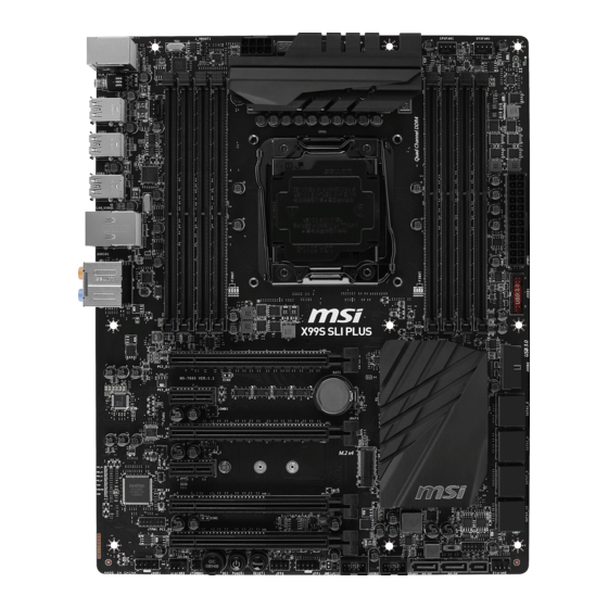
    Français Merci d’avoir choisi une carte mère ATX de la série X99S SLI PLUS (MS- 7885 v1.X). La série X99S SLI PLUS est basée sur le chipset Intel X99 pour ® une efficacité optimale. Conçue pour fonctionner avec les processeurs Intel ®...
  • Page 108: Spécifications

    USB 2.0 internes) ■ ASMedia ASM1042AE - 2x ports USB 3.0 sur le panneau arrière ■ VIA VL805 - 4x ports USB 3.0 sur le panneau arrière * Le connecteur JUSB1 supporte MSI Super Charger. Audio ■ Realtek ALC892 Codec ®...
  • Page 109 ■ 1x contrôleur Intel I218 Gigabit LAN Connecteurs ■ 1x port combo clavier/ souris PS/2 ■ 2x ports USB 2.0 sur le ■ 1x bouton d’effacement CMOS panneau ■ 8x ports USB 3.0 arrière ■ 1x port LAN (RJ45) ■ 1x connecteur S/PDIF OUT optique ■...
  • Page 110 Logiciel ■ Pilotes ■ MSI - Command Center - Live Update 6 - Smart Utilities - Super Charger - Fast Boot - ECO Center ■ Norton Internet Security Solution ■ Intel Extreme Tuning Utility Dimension ■ Dimensions ATX ■ 12 in. x 9.6 in. (30.5 cm x 24.4 cm) Pour plus d’information sur le CPU, veuillez visiter...
  • Page 111: Block Diagram

    Block Diagram 4 Channel DDR4 Memory Haswell-E Processor LGA2011-3 CPU Switch PCIe x1 slot PCI Express Bus (for 40 lanes CPU only) Switch PCI Express Bus Intel I218 Gigabit LAN DMI 2.0 1 x M.2 Switch 1 x SATA Express PCIe x1 slot 10 x SATA 6Gb/s (2 ports reserved for SATA Express)
  • Page 112 Guide Rapide Des Connecteurs JPWR2 CPUFAN2 DIMM1 DIMM8 SYSFAN1 DIMM2 DIMM7 DIMM3 DIMM6 DIMM4 DIMM5 CPUFAN1 JBAT1 Panneau arrière JPWR1 JUSB1 JCI1 PCI_E1 JUSB2 PCI_E2 SATA1_2 PCI_E3 SATA3_4 PCI_E4 SATA7_8 M2_1 PCI_E5 SATA9_10 JTPM1 PCI_E6 BIOS1 SYSFAN2 JAUD1 SYSFAN3 SATA6 SATA5 JSLOW1 JUSB4...
  • Page 113: Guide Référence Des Connecteurs

    Guide référence des connecteurs Noms de ports Types des ports Page Panneau arrière Fr-8 BIOS1 Interrupteur Multi-BIOS Fr-30 CPUFAN1~2,SYSFAN1~3 Connecteurs d'alimentation de ventilateurs Fr-22 LGA2011-3 CPU Socket Fr-11 DIMM1~8 Emplacements de mémoire Fr-14 JAUD1 Connecteur audio avant Fr-26 JBAT1 Cavalier d’effacement CMOS Fr-29 JCI1 Connecteur intrusion châssis...
  • Page 114: Guide Rapide Du Panneau Arrière

    Guide rapide du panneau arrière Port LAN Port PS/2 CS-Out Ligne-In/ SS-Out Port USB 3.0 Port USB 3.0 Bouton d’effacement RS-Out Ligne-Out CMOS Port USB 2.0 Port USB 3.0 Port USB 3.0 S/PDIF-Out optique ▶ Port PS/2 Connecteur souris / clavier PS/2 DIN pour une souris ou un clavier PS/2 ®...
  • Page 115 ▶ Port LAN La prise standard RJ-45 LAN sert à la connexion au réseau local (Local Area Network (LAN)). LED Status Description No link Link/ Activity LED Yellow Linked LINK/ACT SPEED Blinking Data activity 10 Mbps connection Speed LED Green 100 Mbps connection Orange 1 Gbps connection...
  • Page 116: Processeur : Cpu

    Processeur : CPU Introduction du LGA2011-3 CPU A la surface du LGA2011-3 CPU vous noterez quatre clés d'alignement ainsi qu'un triangle jaune pour assister l'alignement correct du CPU sur la position de carte mère. Le triangle jaune corresponde à la Pin 1.
  • Page 117: Installation Du Cpu Et Son Ventilateur

    Installation du CPU et son ventilateur Quand vous installez un CPU, assurez-vous toujours que le CPU soit équipé d’un ventilateur, qui est nécessaire pour éviter la surchauffe et maintenir la stabilité. Suivez les instruction suivantes pour installer le CPU et son ventilateur correctement. Une installation incorrecte peut endommager votre CPU et la carte mère.
  • Page 118 5. Alignez le CPU pour dans la douille CPU. Assurez-vous de maintenir le CPU par la base avec les contacts métaux vers le bas. Les clés d'alignement sur le CPU s'alignent avec les bords de la douille pour garantir la bonne position. 6.
  • Page 119 9. Appliquez une couche de pâte thermique (ou d’adhésif thermique) sur le dessus du CPU. Cela aide la dissipation de chaleur et prévient la surchauffe du CPU. 10. Localisez le connecteur du ventilateur CPU sur la carte mère. CPUFAN1 Pâte thermique 11.
  • Page 120: Mémoire

    Mémoire Ces emplacements DIMM sont destinés à installer les modules de mémoire. DIMM1 DIMM2 DIMM3 DIMM4 DIMM8 DIMM7 DIMM6 DIMM5 SATA9_10 SATA7_8 SATA3_4 SATA1_2 Démonstration de vidéo Voir le vidéo sur l'installation des mémoires sur le site ci-dessous. http://youtu.be/T03aDrJPyQs Jusqu'au mode Quatre Canaux Cette carte mère supporte la mémoire jusqu'à...
  • Page 121: Dimm1, Dimm5

    Conseils pour la règle de population du mode multi-canaux Mode double-canaux DIMMs installé Diagramme (2 modules de mémoire) DIMM1 DIMM2 DIMM3 DIMM4 DIMM1, DIMM5 DIMM8 DIMM7 DIMM6 DIMM5 Mode triple-canaux DIMMs installé Diagramme (3 modules de mémoire) DIMM1 DIMM2 DIMM3 DIMM4 DIMM1, DIMM3, DIMM5 DIMM8...
  • Page 122: Dimm1 Dimm2

    Mode quatre-canal DIMMs installé Diagramme (6 modules de mémoire) DIMM1 DIMM2 DIMM3 DIMM4 DIMM1, DIMM2, DIMM3, DIMM5, DIMM6, DIMM7 DIMM8 DIMM7 DIMM6 DIMM5 DIMMs installé Diagramme (8 modules de mémoire) DIMM1 DIMM2 DIMM3 DIMM1, DIMM2, DIMM4 DIMM3, DIMM4, DIMM5, DIMM6, DIMM8 DIMM7, DIMM8 DIMM7...
  • Page 123: Trous Taraudés De Montage

    Trous Taraudés de Montage Avant d’installer votre carte mère, il faut d’abord installer les socles de montage néce saires sur le plateau de montage du boîtier de l’ordinateur. Si le boîtier de l’ordinateur est accompagné par un panneau Entrée/ Sortie arrière, veuillez le remplacer et utiliser celui qui est fournit dans la boîte de la carte.
  • Page 124: Connecteurs D'alimentation

    Connecteurs d’alimentation Démonstration de vidéo Voir le vidéo sur l’installation des connecteurs d’alimentation sur le site ci-dessous. http://youtu.be/gkDYyR_83I4 JPWR1~2 : Connecteur d'alimentation ATX Ce connecteur vous permet de relier une alimentation ATX. Pour cela, alignez le câble d’alimentation avec le connecteur et appuyez fermement le câble dans le connecteur. Si ceci est bien fait, la pince sur le câble d’alimentation doit être accrochée sur le connecteur d’alimentation de la carte mère.
  • Page 125: Emplacements D'extension

    Emplacements d’extension Cette carte mère contient de nombreux ports pour les cartes d’extension, tels que les cartes graphiques ou les cartes audio. PCI_E1~6 : Emplacement d’extension PCIe L'emplacement PCIe supporte l'interface de carte d'extension PCIe. Emplacement PCIe 3.0 x16 Emplacement PCIe 2.0 x1 Tableau de débit PCIe ■...
  • Page 126: Connecteurs Internes

    Connecteurs internes SATA1~10 : Connecteurs SATA Ce connecteur est un port d’interface SATA haut débit. Chaque connecteur peut être relié à un appareil SATA. Les appareils SATA sont des disques durs (HDD), disque état solide (SSD), et lecteurs optiques (CD/ DVD/ Blu-Ray). Démonstration de vidéo Voir le vidéo sur l’installation d’un SATA HDD.
  • Page 127: Sata_Ex1 : Connecteur Sata Express

    SATA_EX1 : Connecteur SATA Express SATA Express, la nouvelle interface de stockage de haute performance, sert à connecter 1 périphérique SATA Express au taux de transfert jusqu’à 10 Gb/s. Connectez le périphérique SATA Express à ce connecteur 3-en-1 via un câble SATA Express.
  • Page 128: Cpufan1~2,Sysfan1~3 : Connecteur D'alimentation Du Ventilateur

    CPUFAN1~2,SYSFAN1~3 : Connecteur d’alimentation du ventilateur Les connecteurs d’alimentation du ventilateur supportent les ventilateurs de type +12V. Si la carte mère est équipée d’un moniteur du matériel système intégré, vous devrez utiliser un ventilateur spécial pourvu d’un capteur de vitesse afin de contrôler le ventilateur de l’unité...
  • Page 129: Jfp1, Jfp2 : Connecteur Panneau Système

    JFP1, JFP2 : Connecteur panneau système Ces connecteurs se connectent aux interrupteurs et LEDs du panneau avant. Le JFP1 est conforme au guide de conception de la connectivité Entrée/sortie du panneau avant Intel . Lors de l’installation des connecteurs du panneau avant, veuillez utiliser ®...
  • Page 130: Jusb1~2 : Connecteurs D'extension Usb

    • La SuperCharger Technology n’est pas disponible sur tous les modèles de carte mère. Veuillez vous référer au site MSI pour vérifier si votre carte mère est équipé de la SuperCharger Technology. • Pour l’iPad, JUSB1 (marqué rouge) peut aussi charger l’iPad en état S3, S4, S5.
  • Page 131: Jusb3~4 : Connecteurs D'extension Usb

    JUSB3~4 : Connecteurs d’extension USB 2.0 Ce connecteur est destiné à connecter les périphériques USB haute vitesse tels que les disques durs USB, les appareils photo numériques, les lecteurs MP3, les imprimantes, les modems et les appareils similaires. Important Notez que les pins VCC et GND doivent être branchées correctement afin d’éviter tout dommage possible.
  • Page 132: Jaud1 : Connecteur Audio Panneau Avant

    JAUD1 : Connecteur audio panneau avant Ce connecteur vous permet de connecter un audio sur le panneau avant.Il est conforme au guide de conception de la connectivité Entrée/sortie du panneau avant Intel ® JTPM1 : Connecteur de Module TPM Ce connecteur est relié à un module TPM (Trusted Platform Module) en option. Veuillez vous référer au manuel du module TPM pour plus d’information détaillée.
  • Page 133: Boutons

    à la section BIOS de ce manuel pour les instructions comment désactiver OC Genie dans le BIOS. • L’utilisation d’OC Genie est à la risque de l’utilisateur. Overclocking n’est jamais garanti par MSI. • Pour assurer un usage réussi d’OC Genie, les composants MSI sont recommandés. Fr-27...
  • Page 134: Power1 : Bouton D'alimentation

    POWER1 : Bouton d’alimentation Ce bouton sert à allumer ou éteindre le système. Appuyez sur ce bouton pour allumer ou éteindre le système. RESET1 : Bouton de réinitialisation Ce bouton sert à réinitialiser le système. Appuyez sur ce bouton pour le réinitialiser. Fr-28...
  • Page 135: Cavaliers

    Cavaliers JBAT1 : Cavalier d’effacement CMOS Il y a un CMOS RAM intégré, qui est alimenté par une batterie externe située sur la carte mère, destiné à conserver les données de configuration du système. Avec le CMOS RAM, le système peut lancer automatiquement le système d’exploitation chaque fois qu’il est allumé.
  • Page 136: Interrupteur

    BIOS avec les étapes suivantes. Préparation : 1. Préparez un disque flash USB. 2. Téléchargez le fichier BIOS à jour sur le site officiel MSI : www.msi.com, et puis décompressez le fichier. 3. Copiez AFUDE238.exe et le fichier BIOS sur le disque flash USB.
  • Page 137: Pilotes Et Utilitaires

    Veuillez suivre les étapes suivantes pour installer les pilotes et les utilitaires pour votre ordinateur neuf. 1. Insérez le disque de pilote MSI dans le lecteur optique. L'écran de réglages apparaît automatiquement si l'autorun est activé dans le système d'exploitation.
  • Page 138: Configuration Bios

    Configuration BIOS CLICK BIOS est développé par MSI qui fournit une interface graphique utilisateur pour régler les paramètres du BIOS a l'aide de la souris et du clavier. Avec CLICK BIOS, vous pouvez modifier les réglages BIOS, surveiller la température du CPU, choisir la priorité...
  • Page 139: Vue D'ensemble

    Vue d'ensemble Entrer dans le BIOS, l'écran suivant apparaît. Indicateur température Langue Favori Information du système Barre priorité de périphérique Bouton virtuel démarrage OC Genie Sélection du Sélection du menu BIOS menu BIOS Ecran de menu ▶ Sélection du menu BIOS Les options suivantes sont disponibles : ■...
  • Page 140 Activer ou désactiver la fonction OC Genie en cliquant sur ce bouton. Lorsqu’il est activé, le bouton s’allume. Activer la fonction OC Genie peut automatiquement overclocker avec le profil d’overclocking optimisé MSI. Important Il est conseillé de ne faire aucune modification au menu OC ni de charger les valeurs par défaut après l’activation de la fonction OC Genie.
  • Page 141 Opération Vous pouvez contrôler le réglage BIOS avec la souris et le clavier. La liste ci-dessous décrit les opérations des touches raccourcis et de la souris. Touches Souris Description <↑↓→← > Choisir un article Choisir un champ <Enter> Choisir une icône/ un domaine Cliquer/ Double-cliquer le bouton gauche <Esc>...
  • Page 142 OC Menu Ce menu est destiné aux utilisateur avancés souhaitant overclocker la carte mère. Important • L’Overclocking manuel du PC n’est recommandé que pour les utilisateurs avancés. • L’Overclocking n’est pas garanti, et une mauvaise manipulation peut invalider votre garantie et endommager sévèrement votre matériel. •...
  • Page 143 Active la fonction OC Genie via le bouton virtuel dans le BIOS ou le bouton physique sur la carte mère. L’activation de la fonction OC Genie peut overclocker automatiquement le système avec le profil d’overclocking MSI optimisé. [By BIOS Options] La fonction OC Genie est activée en cliquant le bouton virtuel OC Genie en haut à...
  • Page 144 ▶ CPU Base Clock Apply Mode [Auto]* Définit le mode d’application pour le CPU base clock ajusté. [Auto] Ce réglage est configuré automatiquement par le BIOS. [Next Boot] Le CPU fonctionne avec base clock ajusté pour le prochain démarrage. [Immediate] Le CPU fonctionne avec base clock ajusté...
  • Page 145 ▶ Memory Fast Boot [Auto] Active ou désactive l'initialisation et le test de la mémoire à chaque démarrage. [Auto] Ce réglage est automatiquement configuré par le BIOS. [Enabled] La mémoire imitera complètement l'archive de la première initiation et la première formation. La mémoire n'est ensuite plus initialisée ni testée au moment du démarrage, de façon à...
  • Page 146 ▶ CPU Switching Frequency [Auto] Définit la vitesse de fonction du PWM pour stabiliser la tension du cœur CPU et minimiser minimize la gamme d'ondulation. L'augmentation de la vitesse de fonction PWM élève la température MOSFET. Il est nécessaire alors de disposer d'une solution de refroidissement adéquate pour MOSFET avant d'augmenter cette valeur.
  • Page 147 ▶ VCCIN Voltage [Auto] Définit la tension d'entrée du CPU. La tension d'entrée du CPU est la source d'alimentation du CPU partagée avec ses composants. ▶ CPU Core/Ring Voltage Mode [Auto]* Choisit le mode de contrôle pour les tensions du cœur CPU/ Ring. [Auto] Ce réglage est configuré...
  • Page 148 ▶ CPU SA Voltage [Auto] Définit les tensions CPU SA. En “Auto”, le BIOS définit ces tensions automatiquement ou vous pouvez les régler manuellement. Ce menu apparaît lorsque “CPU SA Voltage Mode” est mis en [Manual Mode]. ▶ XXX Voltage [Auto]* (en option) Définit les tensions relatives à...
  • Page 149 ▶ Core0~X [Enabled] Active ou désactive le cœur CPU. Ces menus n’apparaîssent qu’avec “Active Processor Cores Control” activé. ▶ Limit CPUID Maximum [Disabled] Active ou désactive la valeur étendue CPUID. [Enabled] Le BIOS limite la valeur d'entrée maximum CPUID pour contourner le problème démarrage de l'ancien système d'exploitation ne prenant pas en charge le processeur avec la valeur étendue CPUID.
  • Page 150 ▶ CPU AES Instructions [Enabled] Active ou désactive le support CPU AES (Advanced Encryption Standard-New Instructions). Ce menu apparaît si le CPU prend cette fonction en charge. [Enabled] Active le support Intel AES. [Disabled] Désactive le support Intel AES. ▶ Intel Adaptive Thermal Monitor [Enabled] Active ou désactive la fonction de régulation adaptative de la température du moniteur Intel pour protéger le CPU contre la surchauffe.
  • Page 151 ▶ Long Duration Power Limit (W) [Auto] Définit la limite d'alimentation de longue durée TDP pour le CPU en mode Turbo Boost. ▶ Long Duration Maintained (s) [Auto] Définit le temps de maintien pour "Long duration power Limit(W)". ▶ Short Duration Power Limit (W) [Auto] Définit la limite d'alimentation de courte durée TDP pour le CPU en mode Turbo Boost.
  • Page 153: Русский

    Русский Благодарим вас за выбор системной платы серии X99S SLI PLUS(MS-7885 v1.X) ATX. Материнские платы серии X99S SLI PLUS на базе чипсета Intel X99 и обеспечивают оптимальную производительность ® системы. Платы серии X99S SLI PLUS, обеспечивают высокую производительность и являются профессиональными платформами для...
  • Page 154: Характеристики Материнской Платы

    доступны через внутренние USB 2.0 разъемы) ■ ASMedia ASM1042AE - 2x порта USB 3.0 на задней панели ■ VIA VL805 - 4x порта USB 3.0 на задней панели * Внутренний JUSB1 разъем поддерживает MSI Super Charger. Аудио ■ Realtek ALC892 Codec ®...
  • Page 155 Разъемы ■ 1x комбинированный порт PS/2 клавиатуры/ мыши ■ 2x порта USB 2.0 на задней ■ 1x кнопка очистки данных CMOS панели ■ 8x портов USB 3.0 ■ 1x порт LAN (RJ45) ■ 1x оптический разъем S/PDIF ВЫХОД ■ 5x OFC аудиоразъемов Разъемы...
  • Page 156 ■ Intel Extreme Tuning Utility Форм-фактор ■ ATX Форм-фактор ■ 12 дюймов x 9.6 дюймов (30.5 см x 24.4 см) Последние сведения о поддержке процессора можно получить по адресу http://www.msi.com/ cpu-support/ Дополнительные сведения о совместимых компонентах можно получить по адресу http://www.msi.com/test-report/...
  • Page 157: Блок-Схема

    Блок-схема 4 Channel DDR4 Memory Haswell-E Processor LGA2011-3 CPU Switch PCIe x1 slot PCI Express Bus (for 40 lanes CPU only) Switch PCI Express Bus Intel I218 Gigabit LAN DMI 2.0 1 x M.2 Switch 1 x SATA Express PCIe x1 slot 10 x SATA 6Gb/s (2 ports reserved for SATA Express) X99 PCH...
  • Page 158: Краткое Руководство По Разъемам

    Краткое руководство по разъемам JPWR2 CPUFAN2 DIMM1 DIMM8 SYSFAN1 DIMM2 DIMM7 DIMM3 DIMM6 DIMM4 DIMM5 CPUFAN1 JBAT1 Задняя панель JPWR1 JUSB1 JCI1 PCI_E1 JUSB2 PCI_E2 SATA1_2 PCI_E3 SATA3_4 PCI_E4 SATA7_8 M2_1 PCI_E5 SATA9_10 JTPM1 PCI_E6 BIOS1 SYSFAN2 JAUD1 SYSFAN3 SATA6 SATA5 JSLOW1 JUSB4...
  • Page 159: Справочное Руководство По Разъемам

    Справочное руководство по разъемам Наименование порта Тип порта Страница Задняя панель Ru-8 BIOS1 Переключатель Multi-BIOS Switch Ru-30 CPUFAN1~2,SYSFAN1~3 Разъемы питания вентиляторов Ru-22 Разъем LGA2011-3 CPU Ru-11 DIMM1~8 Память Ru-14 JAUD1 Аудио коннектор передней панели Ru-26 JBAT1 Джампер очистки данных CMOS Ru-29 JCI1 Разъем...
  • Page 160: Краткое Руководство По Работе С Задней Панелью

    Краткое руководство по работе с задней панелью Порт LAN Порт PS/2 Линейный Порт USB Порт USB 3.0 CS-Выход вход/SS-Выход Кнопка очистки Линейный RS-Выход CMOS выход Порт USB Микрофон Порт USB 2.0 Порт USB 3.0 Оптический выход S/PDIF ▶ Порт PS/2 Комбинированный...
  • Page 161 ▶ Порт LAN Стандартный разъем RJ-45 для подключения к локальной вычислительной сети (LAN). Состояние Индикатор Описание индикатора Выкл. Не подключен Link/ Activity LED (Подключение/ Желтый Подключен LINK/ACT SPEED Работа индикатора) Мигает Передача данных Выкл. 10 Мбит/с подключение Speed LED (Скорость Зеленый...
  • Page 162: Цп (Центральный Процессор)

    выполнением разгона системы убедитесь в том, что все компоненты системы смогут выдержать разгон. Производитель не рекомендует использовать параметры, выходящие за пределы технических характеристик устройств. Гарантия MSI не распространяется на повреждения и другие возможные последствия ненадлежащей эксплуатации и несоблюдения технических характеристик изделия.
  • Page 163 Установка ЦП и радиатора При установке процессора обязательно установите радиатор ЦП. Радиатор ЦП предупреждает перегревание и обеспечивает стабильность работы системы. Ниже представлены инструкции по правильной установке процессора и радиатора ЦП. Неправильная установка приводит к выходу из строя процессора и материнской платы. Видео...
  • Page 164 5. Выравняйте процессор относительно сокета. Процессор необходимо держать за края контактами вниз. Для правильной установки ключи на процессоре должны совпадать с ключами сокета. 6. Закройте загрузочную пластину и удалите защитную пластиковую крышку. Ключи совмещения 7. Аккуратно закройте прижимной рычаг и зафиксируйте его на сокете. 8.
  • Page 165 9. Ровно нанесите тонкий слой термопасты на поверхность процессора. Это поможет улучшить теплоотвод и предотвратит перегрев процессора. 10. Найдите на плате коннектор процессорного вентилятора. CPUFAN1 Термопаста 11. Расположите радиатор охлаждения так, чтобы его провода смотрели на коннектор питания вентилятора, а элементы крепления располагались над соответствующими...
  • Page 166: Память

    Память Разъемы DIMM предназначены для установки модулей памяти. DIMM1 DIMM2 DIMM3 DIMM4 DIMM8 DIMM7 DIMM6 DIMM5 SATA9_10 SATA7_8 SATA3_4 SATA1_2 Видео Демонстрация Смотрите видео, чтобы узнать как установить память по указанному адресу. http://youtu.be/T03aDrJPyQs Поддержка четырехканального режима работы Эта плата поддерживает четырехканальный режим работы памяти. Два DIMM слота...
  • Page 167: Dimm8 Dimm7 Dimm6 Dimm5

    Установка модулей памяти в многоканальном режиме Двух канальный режим Установлены модули DIMM (2 Схема установки модуля памяти) DIMM1 DIMM2 DIMM3 DIMM4 DIMM1, DIMM5 DIMM8 DIMM7 DIMM6 DIMM5 Трех канальный режим Установлены модули DIMM (3 Схема установки модуля памяти) DIMM1 DIMM2 DIMM3 DIMM4 DIMM1, DIMM3, DIMM5...
  • Page 168: Dimm8 Dimm7 Dimm6 Dimm5

    Четырех канальный режим Установлены модули DIMM (6 Схема установки модулей памяти) DIMM1 DIMM2 DIMM3 DIMM4 DIMM1, DIMM2, DIMM3, DIMM5, DIMM6, DIMM7 DIMM8 DIMM7 DIMM6 DIMM5 Установлены модули DIMM (8 Схема установки модулей памяти) DIMM1 DIMM2 DIMM3 DIMM1, DIMM2, DIMM4 DIMM3, DIMM4, DIMM5, DIMM6, DIMM8 DIMM7, DIMM8...
  • Page 169: Отверстия Под Установочные Винты

    Отверстия под установочные винты Для установки материнской платы на монтажной плате системного блока сначала установите необходимые установочные стойки. Если в комплект поставки системного блока входит задняя панель ввода-вывода, замените ее задней панелью ввода-вывода, которая поставляется с материнской платой. Задняя панель ввода-вывода без труда устанавливается в системном блоке...
  • Page 170: Электропитание

    Электропитание Видео Демонстрация Смотрите видео, чтобы узнать как установить разъем питания. http://youtu.be/gkDYyR_83I4 JPWR1~2: Разъемы питания ATX Эти разъемы предназначены для подключения разъема питания ATX. Для подключения ATX разъема питания совместите кабель питания с разъемом и прочно закрепите его. При правильном выполнении подключения защелка на кабеле...
  • Page 171: Pci_E1~6: Слоты Расширения Pcie

    Слоты расширения Данная материнская плата содержит множество разъемов для установки плат расширения, в частности, дискретных видеокарт или звуковых карт. PCI_E1~6: Слоты Расширения PCIe Слот PCIe поддерживает платы расширения с интерфейсом PCIe. PCIe 3.0 x16 слот PCIe 2.0 x1 слот Таблица пропускной способности PCIe ■...
  • Page 172: Внутренние Разъемы

    Внутренние разъемы SATA1~10: Разъемы SATA Данный разъем является высокоскоростным интерфейсом SATA. К любому разъему SATA можно подключить одно устройство SATA. К устройствам SATA относятся жесткие диски, твердотельные накопители и накопители на оптических дисках (компакт-диски/ DVD-диски/ Blu-Ray-диски). Видео Демонстрация Смотрите видео, чтобы узнать как установить SATA жесткие...
  • Page 173 SATA_EX1: Разъем SATA Express SATA Express, новый интерфейс хранения высокой производительности, поддерживает подключения 1 устройство SATA Express со скоростью передачи до 10 Гбит/с. Подключается устройство SATA Express к этому 3-в-1 разъему с помощью кабеля SATA Express. M2_1: Порт M.2 Порт M.2 поддерживает как модули M.2 SATA 6Гб/с, так и модули M.2 PCIe. Видео...
  • Page 174 CPUFAN1~2, SYSFAN1~3: Разъемы питания вентиляторов Разъемы питания вентиляторов поддерживают вентиляторы с питанием +12 В. Если на системной плате установлена микросхема аппаратного мониторинга, необходимо использовать специальные вентиляторы с датчиками скорости для использования функции управления вентиляторами. Обязательно подключите все системные вентиляторы. Некоторые системные вентиляторы невозможно подключить...
  • Page 175 JFP1, JFP2: Разъемы панели системы Эти разъемы служат для подключения кнопок и светодиодных индикаторов, расположенных на передней панели. Разъем JFP1 соответствует стандарту Intel Front Panel I/O Connectivity Design. При установке разъемов передней ® панели для удобства используются переходники и кабели, входящие в комплект поставки.
  • Page 176 скорость передачи данных до 5 Гбит/с(SuperSpeed). Разъем JUSB1 (красный значок) поддерживает новую технологию SuperCharger от компании MSI, которая обеспечивает ускоренную зарядку сотового телефона или другого устройства, подключаемого к разъему USB. Для активации этой функции установите приложение MSI SuperCharger в свой компьютер. При...
  • Page 177: Jci1: Разъем Датчика Открытия Корпуса

    JUSB3~4: Разъемы расширения USB 2.0 Этот разъем служит для подключения таких высокоскоростных периферийных устройств, как жесткие диски с интерфейсом USB, цифровые камеры, МРЗ плееры, принтеры, модемы и т. д. Внимание Помните, что во избежание повреждений необходимо правильно подключать контакты VCC и GND. JCI1: Разъем...
  • Page 178: Jtpm1: Разъем Модуля Трм

    JAUD1: Аудио коннектор передней панели Этот коннектор служит для подключения аудиоразъемов передней панели системного блока. Коннектор соответствует стандарту Intel Front Panel I/O Con- ® nectivity Design. JTPM1: Разъем модуля ТРМ Данный разъем подключается к модулю ТРМ (Trusted Platform Module). Дополнительные сведения см. в описании модуля безопасности ТРМ. Ru-26...
  • Page 179: Кнопки

    отключению функции OC Genie из BIOS представлены в разделе BIOS руководства пользователя. • Ответственность за применение функции OC Genie и его последствия несет пользователь. Компания MSI никогда не гарантирует успешность и результаты «разгона» системы. • Для успешной работы функции OC Genie рекомендуется использовать...
  • Page 180 POWER1: Кнопка питания Эта кнопка предназначена для включения и выключения системы. Нажмите на кнопку один раз для включения или выключения системы. RESET1: Кнопка перезагрузки Эта кнопка предназначена для перезагрузки системы. Нажмите на нее для сброса системы. Ru-28...
  • Page 181: Джампер

    Джампер JBAT1: Джампер очистки данных CMOS На плате установлена CMOS память с питанием от батарейки для хранения данных о конфигурации системы. С помощью памяти CMOS операционная система (ОС) автоматически загружается каждый раз при включении. Для сброса конфигурации системы (очистки данных CMOS памяти), воспользуйтесь этой перемычкой.
  • Page 182: Переключатели

    вы можете восстановить BIOS, следуя инструкции ниже. Необходимо приготовить: 1. Приготовьте загрузочную USB флэшку. 2. Скачайте и разархивируйте с официального сайта MSI www.msi.com последнюю версию BIOS. 3. Скопируйте файл BIOS и AFUDE238.exe на загрузочную USB флэшку. Пошаговая инструкция восстановления BIOS: 1.
  • Page 183: Драйверы И Утилиты

    Установка драйверы и утилит Для установки драйверов и утилит на своем компьютере следуйте приведенным ниже указаниям. 1. Вставьте диск с драйверами MSI Driver Disc в привод для оптических дисков. Если в операционной системе включена функция автозапуска, автоматически отобразится утилита installer.
  • Page 184: Настройка Bios

    на экране утилиты "MSI Fast Boot". Внимание • Не забудьте установить “MSI Fast Boot” до того как войти в настройки BIOS. • Для улучшения работы системы содержимое каждого из разделов BIOS, рассматриваемое в данной главе, постоянно совершенствуется. Поэтому для новых версий BIOS оно может несколько отличаться от данного описания, которое...
  • Page 185: Общие Сведения

    Общие Сведения После входа в BIOS отображается следующий экран. Мониторинг температур Избранное Язык Системная Информация Приоритет загрузочных Кнопка Virtu- устройств al OC Genien Выбор меню Выбор меню BIOS BIOS Экран просмотра раздела ▶ Выбор меню BIOS Доступны следующие опции: ■ SETTINGS - В...
  • Page 186 ▶ Кнопка Virtual OC Genie Включает или выключает функции OC Genie, при нажатии кнопки. Данная кнопка мигает при включении. Включение функции OC Genie приводит к автоматическому разгону с оптимизированным профилем MSI. Внимание Мы рекомендуем не делать никаких изменений в меню OC и не загружать...
  • Page 187 Работа Вы можете управлять параметрами настройки BIOS с помощью мыши и клавиатуры. В нижеследующей таблице представлен перечень и описание «клавиш быстрого вызова» и функций мыши. Клавиша Mыши Описание быстрого вызова <↑↓→← > Выбор элемента Перемещение указателя <Enter> Выбор значка/ поля Щелчок/ Двойной...
  • Page 188 Меню OC Данное меню предназначено для опытных пользователей и предоставляет возможности для "разгона" системы. Внимание • Разгонять ПК вручную рекомендуется только опытным пользователям. • Производитель не гарантирует успешность разгона. Неправильное выполнение разгона может привести к аннулированию гарантии и серьезному повреждению оборудования. •...
  • Page 189 Для включения функции OC Genie нажмите виртуальную кнопку в BIOS или физическую кнопку на материнской плате. Включение функции OC Genie позволяет автоматически разгонять систему с оптимизированным профилем разгона MSI. [By BIOS Options] Для включения функции OC Genie нажмите на виртуальную...
  • Page 190 ▶ Adjusted Ring Frequency Показывает скорректированную частоту шины Ring. Это значение нельзя изменять. < Настройка BCLK процессора > ▶ CPU Base Clock (MHz) [Default] Установка базовой тактовой частоты ЦП. Изменение этого параметра обеспечивает возможность «разгона» ЦП. Обращаем ваше внимание на то, что...
  • Page 191 ▶ DRAM Timing Mode [Auto] Режимы таймингов памяти. [Auto] Временные параметры DRAM устанавливаются на основе SPD (Serial Presence Detect) модуля памяти. [Link] Позволяет пользователю настроить тайминги DRAM вручную для всех каналов памяти. [UnLink] Позволяет пользователю настроить тайминги DRAM вручную для соответствующего...
  • Page 192 ▶ CPU Vdroop Offset Control [Auto] Устанавливает напряжение смещения в процентах для vdroop процессора. При установке в "Auto", BIOS автоматически настроит этот параметр. ▶ CPU Over Voltage Protection [Auto] Устанавливает верхнюю границу максимального напряжения для защиты процессора от слишком высокого напряжения. Если установлено "Auto", BIOS автоматически...
  • Page 193 ▶ DRAM CH_A/B, CH_C/D Over Current Protection [Auto] Устанавливает ограничение по максимальному току для защиты DRAM. [Auto] Этот параметр будет настроен автоматически с помощью BIOS. [Enhanced] Расширяет ограничение тока для защиты памяти. ▶ DRAM CH_A/B, CH_C/D Switching Frequency [Auto] Устанавливает скорость работы PWM для стабилизации напряжения DRAM и...
  • Page 194 ▶ CPU Core/ Ring Voltage Offset Mode [Auto]* Выбор режима смещения для ядра процессора/ шины Ring. Этот пункт появляется, когда “CPU Core/Ring Voltage Mode” установлено в [Offset Mode]/ [Adaptive + Offset]/ [Override + Offset]. [Auto] Параметр будет настроен автоматически с помощью BIOS. Позволяет...
  • Page 195 < Другие настройки > ▶ CPU Memory Changed Detect [Enabled]* Включение или выключение предупреждающих сообщений при загрузке системы, когда процессор или память были заменены. [Enabled] Система выдает предупреждение во время загрузки. Требуется загрузить настройки по умолчанию для новых устройств. [Disabled] Выключение...
  • Page 196 ▶ Execute Disable Bit [Enabled] Функция Intel’s Execute Disable Bit позволяет защититься от некоторых видов злонамеренных действий типа «ошибки переполнения буфера», при которых вирусы пытаются выполнить код, разрушающий систему. Рекомендуется не отключать данную функцию. [Enabled] NO-Execution позволяет защититься от злонамеренных действий и...
  • Page 197 ▶ Intel Adaptive Thermal Monitor [Enabled] Включение или выключение этой функции для защиты процессора от перегрева. [Enabled] Уменьшает частоту ядра процессра, когда процессор превышает адаптивную температуру. [Disabled] Выключение функции. ▶ Intel C-State [Enabled] C-state - это технология управления питанием процессора, определяется ACPI.
  • Page 198 ▶ Long Duration Maintained (s) [Default] Настроить максимальное время работы процессора с ограничением мощности при Long Duration Power Limit. ▶ Short Duration Power Limit (W) [Auto] Настроить предельную мощность TDP на короткий срок для процессора в режиме Turbo Boost. ▶ CPU Current Limit (A) [Auto] Устанавливает...
  • Page 199: Installation/Установка

    Installation/ Установка This chapter provides demonstration diagrams about how to install your computer. Some of the installations also provide video demonstrations. Please link to the URL to watch it with the web browser on your phone or tablet. You may have even link to the URL by scanning the QR code. Das vorliegende Kapitel bietet die Demo-Diagrammen, wie Sie Ihren Computer zu installieren.
  • Page 200: Cpu

    Youtube http://youtu.be/WPhyn2C5mgs...
  • Page 202: Memory/ Speicher/ Mémoire/ Памяти

    Memory/ Speicher/ Mémoire/ Памяти http://youtu.be/T03aDrJPyQs...
  • Page 203: Motherboard/ Carte Mère/ Материнские Платы

    Motherboard/ Carte mère/ Материнские платы...
  • Page 205: Power Connector/ Atx-Stromanshcluss/Connecteurs D'alimentation/ Pазъема Питания

    Power Connector/ ATX-Stromanshcluss/ Connecteurs d'alimentation/ Pазъема питания http://youtu.be/gkDYyR_83I4...
  • Page 206 oder или...
  • Page 207: Sata Hdd

    SATA HDD http://youtu.be/RZsMpqxythc oder или oder или...
  • Page 208 Youtube http://youtu.be/JCTFABytrYA 30° A-10...
  • Page 209: Front Panel Connector/ Frontpanel Anschluss/ Connecteur Panneau Avant/Pазъемов Передней Панели

    Front Panel Connector/ Frontpanel Anschluss/ Connecteur panneau avant/ Pазъемов передней панели JFP1 http://youtu.be/DPELIdVNZUI JAUD1 A-11...
  • Page 210: Peripheral Connector/ Peripheriestecker/Connecteur Périphérique/ Периферийных Разъемов

    Peripheral Connector/ Peripheriestecker/ Connecteur périphérique/ Периферийных разъемов USB2.0 oder или USB3.0 A-12...
  • Page 211: Graphics Card/ Grafikkarte/ Carte Graphique/Bидеокарты

    Graphics Card/ Grafikkarte/ Carte graphique/ Bидеокарты http://youtu.be/mG0GZpr9w_A A-13...
  • Page 212 A-14...