
Manuels Connexes pour Mitsubishi Electric Al2 Série


Sommaire des Matières pour Mitsubishi Electric Al2 Série
- Page 1 α 2 Simple Application Controller HARDWARE MANUAL HARDWARE-HANDBUCH MANUEL DU MATÉRIEL MANUALE HARDWARE MANUAL DE HARDWARE MASKINVARUHANDBOK...
- Page 2 2 series always consult a professional electrical engineer who is qualified and trained to the local and national standards. If in doubt about the operation or use of the a series controller please consult the nearest Mitsubishi Electric distributor. •...
- Page 3 α 2 Simple Application Controller α 2 Simple Application Controller Hardware Manual Manual number: JY992D97301 Manual revision: B Date: 06/2002 ENG-i...
- Page 4 α 2 Simple Application Controller ENG-ii...
- Page 5 Mitsubishi users are always welcomed. This page has been designed for you, the reader, to fill in your comments and fax them back to us. We look forward to hearing from you. Fax numbers: Your name............ Mitsubishi Electric................. America (01) 847-478-2253 Your company ..........
- Page 6 α 2 Simple Application Controller ENG-iv...
- Page 7 α 2 Simple Application Controller Guidelines for the Safety of the User and Protection of equipment α This manual provides information for the use of the 2 Series Controllers. The manual has been written to be used by trained and competent personnel. The definition of such a person or persons is as follows;...
- Page 8 α 2 Simple Application Controller • Under no circumstances will Mitsubishi Electric be liable or responsible for any consequential damage that may arise as a result of the installation or use of this equipment. • All examples and diagrams shown in this manual are intended only as an aid to understanding the text, not to guarantee operation.
-
Page 9: Table Des Matières
α 2 Simple Application Controllers Table of Contents Guidelines of Safety ..............ENG-v 1. Introduction..................ENG-1 α 1.1 Special Features of the 2 Series System............ ENG-2 1.2 Available Models ................... ENG-3 1.3 Dimensions and Each Part Name ..............ENG-4 1.4 System Configuration ..................ENG-5 1.5 Applicable Programming Software .............. - Page 10 α 2 Simple Application Controllers 7. AL-232CAB ...................ENG-31 7.1 Introduction....................ENG-31 7.1.1 External Dimensions ..................ENG-31 7.2 Connected to AL-232CAB cable..............ENG-32 8. AL2-GSM-CAB ................ENG-35 8.1 Introduction....................ENG-35 8.1.1 External Dimensions ..................ENG-35 8.1.2 System Configuration with using AL2-GSM-CAB..........ENG-36 8.2 Installation ....................
-
Page 11: Introduction
α Introduction 1 2 Simple Application Controllers Introduction α 2 series can be easily used in all places where control is needed for the home, office, or factory. The controller outputs cycle ON/OFF to control electrical equipment per the Function Block program. -
Page 12: Special Features Of The Α 2 Series System
α Introduction 1 2 Simple Application Controllers α Special Features of the 2 Series System 1) Display message and Function Block data α 2 series can display the state of operation and the alarm on the LCD display as a message. -
Page 13: Available Models
α Introduction 1 2 Simple Application Controllers Available Models Table 1.2:Main Units Input Output MASS Power Dimensions Model (Weight) Supply mm (inches) Type Number Type Number kg (lbs) 100 - 240V 100 - 240V AL2-14MR-A RELAY 0.30 (0.66) 24V DC 124.6 x 90 x 52 AL2-14MR-D 24V DC... -
Page 14: Dimensions And Each Part Name
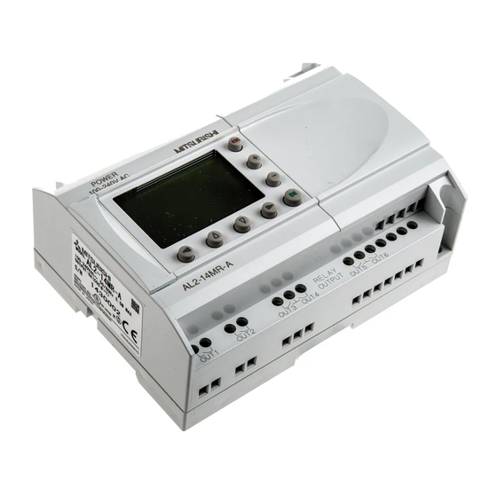
α Introduction 1 2 Simple Application Controllers Dimensions and Each Part Name Figure 1.1: Each Part Name ‚ „ ƒ 6 ( 0 . 2 4 " ) E 0 1 E 0 2 D C I N P U T ( A ) ( B ) †... -
Page 15: System Configuration
α Introduction 1 2 Simple Application Controllers System Configuration Figure 1.2: System Configuration Standard Connection to the Programming Softoware α Using Dedicated Protocol Series Remote Maintenance (via Telephone Line) Normal Modem Normal Modem Personal computer - Programming Software (AL-PCS/WIN-E) - Dedicated protocol Remote Maintenance, e-Mail (via GSM) - e-Mail application Normal Modem... - Page 16 α Introduction 1 2 Simple Application Controllers MEMO ENG-6...
-
Page 17: Specifications
α Specifications 2 2 Simple Application Controllers Specifications Power Supply Specification Table 2.1: Power Supply Specifications Description Code Specification AL2-***-A 100 - 240V AC~, +10% -15%, 50/60 Hz Power Supply AL2-***-D 24V DC, +20% -15% AL2-***-A 10ms Maximum Momentary Power Failure AL2-***-D AL2-***-A,... -
Page 18: Input Specification
α Specifications 2 2 Simple Application Controllers Input Specification Table 2.2: AC Input Specifications AC Input Specification Description main unit AL2-4EX-A2 I01 - I08 I09 - I15 EI1 - EI4 220 - 240V AC~, +10% -15%, Input Voltage 100 - 240V AC~, +10% -15%, 50/60 Hz 50/60 Hz 0.13mA / 120V AC~ 0.15mA / 120V AC~... - Page 19 α Specifications 2 2 Simple Application Controllers Table 2.4: Analog Input Specifications (Only AL2-***-D Type Unit) Description Analog Input Specification Number of Input Points 8 (I01 - I08) Analog Input Range 0 - 500 Resolution 9 bit, 20mV (10000/ 500mv) Conversion Speed Input Voltage 0 - 10V DC...
-
Page 20: Output Specification
α Specifications 2 2 Simple Application Controllers Output Specification Table 2.5: Relay Output Specifications Description Relay Specification Switched Voltage 250V AC~ or less, 30V DC or less AL2-14MR-* (O01 - O06) 8A/COM AL2-24MR-* (O01 - O04) Max. Resistive Load AL2-24MR-* (O05 - O09) 2A/point (4A/COM) AL2-4EYR (EO1 - EO4) 2A/point AL2-14MR-* (O01 - O06) -
Page 21: General Specification
α Specifications 2 2 Simple Application Controllers General Specification Table 2.7: Environmental and Electrical Specifications Description Specification Programming Method Function Block Program Capacity 200 Function Blocks or 5000 bytes Built in EEPROM (no battery backup required) or optional EEPROM Program Storage cassette (AL2-EEPROM-2) Device Backup 20 Days at 25°C / 77°F (by capacitor) - Page 22 α Specifications 2 2 Simple Application Controllers Table 2.7: Environmental and Electrical Specifications Description Specification Temperature for the Ball 75°C (167°F) Pressure Test EC Directive EMC, LVD Certifications UL/cUL Attestation of Conformity TÜV PRODUCT SEVICE UL 508 IEC 60730-1 EN 61010-1 Complies with EN 50081-1 EN 50082-1...
-
Page 23: Installation
α Installation 3 2 Simple Application Controllers Installation Installation Mounting Notes α 2 Series’ safe design means the user can install it almost anywhere but please take the following points into consideration. • Do not install in areas with excessive or conductive dust, corrosive or flammable gas, moisture or rain, excessive heat, regular impact shocks or excessive vibration. -
Page 24: Din Rail Mounting Of Main Unit
α Installation 3 2 Simple Application Controllers DIN RAIL Mounting of Main Unit Units can be snap mounted to 35mm DIN rail (DIN EN 50022). To release pull the spring loaded clips away from the rail and slide the unit off and up. 3.2.1 Installation Figure 3.2: Installation... -
Page 25: Direct Mounting Of Main Unit
α Installation 3 2 Simple Application Controllers Direct Mounting of Main Unit Figure 3.4: Direct Mounting 124.6 (4.91") 6 (0.24") 112.6 (4.43") 6 (0.24") Main Unit M4 Mounting Screw Install Extension Module Caution: Disconnect all terminals from the power supply before removing the cover. ENG-15... - Page 26 α Installation 3 2 Simple Application Controllers Figure 3.5: Installation 1) Release screw ‘A’ and keep. D C I N P U T ( A ) ( B ) 2) Carefully remove the factory fitted expansion P O W E R 2 4 V D C E S C port cover.
-
Page 27: Wiring
α Wiring 4 2 Simple Application Controllers Wiring Installation Wiring Notes α The wiring of 2 Series has been designed to be safe and easy. A technician or engineer trained in the local and national electrical standards should perform all tasks associated α... -
Page 28: Wire Size
α Wiring 4 2 Simple Application Controllers Wire Size Wire of the Inputs and Outputs using the following wire. Strip the wire to the following length (See Table 4.1 and Figure 4.1). Please unscrew the terminal to its widest position before inserting a wire. -
Page 29: Power Supply
α Wiring 4 2 Simple Application Controllers Power Supply • When wiring AC supplies the “Live” cable should be connected to the “L” terminal and the “Neutral” cable should be connected to the “N” terminal. Do NOT connect the “Live” wire to the “N”... -
Page 30: Ac Power Supply And Input Wiring
α Wiring 4 2 Simple Application Controllers AC Power Supply and Input Wiring 4.4.1 AC Power Supply and Input Wiring Figure 4.3: AC Power Supply and Input Wiring Diagram "L" and "N" terminals are not reversible. 1 2 3 4 5 6 INPUTS Table 4.3: AC Power Supply and Input Wiring... -
Page 31: Dc Power Supply And Input Wiring
α Wiring 4 2 Simple Application Controllers DC Power Supply and Input Wiring 4.5.1 DC Power Supply and Source (“+” Common) Input Wiring Diagram Figure 4.5: DC Power Supply and Source (“+” Common) Input Wiring Diagram 1 2 3 4 5 6 (A) (B) INPUTS Table 4.5: DC Power Supply and Source (“+”... -
Page 32: Dc Power Supply And Sink ("-" Common) Input Wiring Diagram
α Wiring 4 2 Simple Application Controllers 4.5.3 DC Power Supply and Sink (“-” Common) Input Wiring Diagram Figure 4.7: DC Power Supply and Sink (”-” Common) Input Wiring Diagram 1 2 3 4 5 6 (A) (B) INPUTS Table 4.7: DC Power Supply and Sink (“-” Common) Input Wiring Ref. -
Page 33: Output Relay And Transistor Wiring
α Wiring 4 2 Simple Application Controllers Output Relay and Transistor Wiring 4.6.1 Relay Output Wiring Diagram main unit (AC and/or DC) Figure 4.9: Relay Output Wiring Diagram main unit (AC and/or DC) OUT1 OUT2 OUT3 OUT4 OUT5 OUT6 Table 4.9: Relay Output Wiring main unit (AC and/or DC) Ref. -
Page 34: Relay Output Wiring Diagram Al2-4Eyr (Ac And/Or Dc)
α Wiring 4 2 Simple Application Controllers 4.6.2 Relay Output Wiring Diagram AL2-4EYR (AC and/or DC) Figure 4.10: Relay Output Wiring Diagram AL2-4EYR (AC and/or DC) Table 4.11: Relay Output Wiring AL2-4EYR (AC and/or DC) Ref. Item Description DC power supply Emergency stop Circuit protection device (Fuse: ≤... -
Page 35: Transistor Output (Source Or "+" Common Only) Wiring Diagram Al2-4Eyt
α Wiring 4 2 Simple Application Controllers 4.6.3 Transistor Output (Source or “+” Common Only) Wiring Diagram AL2-4EYT Figure 4.11: Transistor Output (Source/ “+” Common Only) Wiring Diagram AL2-4EYT EO1 EO2 EO3 EO4 Table 4.13: Transistor Output Wiring Ref. Item Description DC Power Supply: 24V DC Emergency Stop Circuit Protection Device - See Table 4.14 for Specifications... - Page 36 α Wiring 4 2 Simple Application Controllers MEMO ENG-26...
-
Page 37: Terminal Layout
α Terminal Layout 5 2 Simple Application Controllers Terminal Layout Figure 5.1: AL2-14MR-A, AC Input, Relay Output AL2-14MR-A OUT1 OUT2 OUT3 OUT4 OUT5 OUT6 Figure 5.2: AL2-14MR-D, DC Input, Relay Output (A) (B) AL2-14MR-D OUT1 OUT2 OUT3 OUT4 OUT5 OUT6 Figure 5.3: AL2-24MR-A, AC Input, Relay Output 10 11 12 13 14 15 AL2-24MR-A... - Page 38 α Terminal Layout 5 2 Simple Application Controllers Figure 5.5: AL2-4EX-A2, 220 - 240V AC Input COM(N) EI2 EI3 EI4 AL2-4EX-A2 Figure 5.6: AL2-4EX, DC Input AL2-4EX Figure 5.7: AL2-4EYR, Relay Output AL2-4EYR Figure 5.8: AL2-4EYT, Transistor Output AL2-4EYT EO3 EO4 ENG-28...
- Page 39 α AL2-EEPROM-2 6 2 Simple Application Controllers AL2-EEPROM-2 α The AL2-EEPROM-2 memory cassette is for use only with the 2 series controller (Model: AL2-**M*-*). Caution • Persons trained in the local and national electrical standards must replace the memory cassette. •...
- Page 40 α AL2-EEPROM-2 6 2 Simple Application Controllers Installation 1) Remove the cover or the memory cassette ‚ ƒ 2) Install on the cover or the memory cassette ‚ ENG-30...
-
Page 41: Al-232Cab
α AL-232CAB 7 2 Simple Application Controllers AL-232CAB Introduction α α α The AL-232CAB is an RS-232C cable used to connect an series controller ( 2) and a personal computer that is running the programming software (AL-PCS/WIN-E). Note: • AL-232CAB cable cannot be used for any other applications. •... -
Page 42: Connected To Al-232Cab Cable
α AL-232CAB 7 2 Simple Application Controllers Connected to AL-232CAB cable Remove cover and memory cassette α • Be careful of personal safety when removing the 2 cover. Caution • Turn off the power supply when you install or detach the AL-232CAB cable. •... - Page 43 α AL-232CAB 7 2 Simple Application Controllers 2) Connecting the AL-232CAB cable 3) Removing the AL-232CAB cable ENG-33...
- Page 44 α AL-232CAB 7 2 Simple Application Controllers 4) Installing on the cover or the memory cassette ‚ ENG-34...
- Page 45 α AL-232CAB 7 2 Simple Application Controllers MEMO ENG-35...
-
Page 46: Al2-Gsm-Cab
α AL2-GSM-CAB 8 2 Simple Application Controllers AL2-GSM-CAB Introduction α The AL2-GSM-CAB can be used to connect 2 Series Controllers to a normal or GSM modem. The AL2-GSM-CAB can transfer Short Message Service (SMS) data to a GSM modem for transmission to mobile phones and mail addresses or can facilitate remote monitoring functions and program transfers via normal modems. -
Page 47: System Configuration With Using Al2-Gsm-Cab
α AL2-GSM-CAB 8 2 Simple Application Controllers 8.1.2 System Configuration with using AL2-GSM-CAB Figure 8.2: System Configuration with AL2-GSM-CAB Using Dedicated Protocol α Series Remote Maintenance (Via Telephone Line) Normal Modem Normal Modem Personal computer Remote Maintenance, E-Mail (Via GSM) - Programming Software (AL-PCS/WIN-E) Normal Modem... -
Page 48: Installation
• Put the cover back on after either installing or removing the AL2-GSM-CAB. • Under no circumstances will Mitsubishi Electric be liable or responsible for any consequential damage that may arise as a result of the installation or use of this equipment. - Page 49 α AL2-GSM-CAB 8 2 Simple Application Controllers Figure 8.4: Installation 1) Release screw ‘A’ and keep. D C I N P U T ( A ) ( B ) α P O W E R 2 4 V D C 2) Carefully remove the factory fitted 2 expansion E S C...
-
Page 50: Remote Maintenace With A Modem
α AL2-GSM-CAB 8 2 Simple Application Controllers Remote Maintenace with a Modem α Further information of the modem setup procedures can be found in the 2 Programming Manual. The programming software (AL-PCS/WIN-E) provides the easiest method to setup the modem. 8.3.1 Recommended Modems The following modems have been successfully tested. -
Page 51: Modem Setting
α AL2-GSM-CAB 8 2 Simple Application Controllers 8.3.3 Modem Setting 1) Setting of personal computer side Install the file for the setting of the attachment in the modem. α 2) Setting of 2 series side α The modem on the 2 series side is set by the ModemInit command of the main unit. - Page 52 α AL2-GSM-CAB 8 2 Simple Application Controllers Table 8.5: AT Command for GSM Modem Example Setting Setting Item Set content M20T Enable command echo Echo mode OFF Set number of ring before Enable automatic answering on the ring S0=2 automatically answering the call twice Set circuit data set ready (DSR) DSR always ON...
- Page 53 α AL2-GSM-CAB 8 2 Simple Application Controllers MEMO ENG-43...
-
Page 54: Al2-Asi-Bd
• Turn off the power supply when you install or remove the AL2-ASI-BD. • Replace the cover after removing the AL2-ASI-BD. • Under no circumstances will Mitsubishi Electric be liable or responsible for any consequential damage that may arise as a result of the installation or use of this equipment. -
Page 55: System Configuration
α AL2-ASI-BD 9 2 Simple Application Controllers 9.1.2 System Configuration Figure 9.2: System Configuration AS-interface Master AS-interface Slave Module (Sensor / Actuator) AS-interface Slave AS-interface AS-interface Slave AS-interface Slave α 2 Series Power Supply (Sensor / Actuator) (Sensor / Actuator) + AL2-ASI-BD) Specifications For general specifications please refer to the Chapter 2. -
Page 56: Wiring & Installation
α AL2-ASI-BD 9 2 Simple Application Controllers Wiring & Installation 9.3.1 Installation Caution Disconnect all terminals from the power supply before removing the cover. Figure 9.3: Installation 1) Release screw ‘A’ and keep. D C I N P U T ( A ) ( B ) 2) Carefully remove the factory fitted expansion... -
Page 57: Wiring
α AL2-ASI-BD 9 2 Simple Application Controllers 9.3.2 Wiring Use the AS-interface flat cable (yellow) for connecting the AL2-ASI-BD to the network. When connecting AS-interface cable to the module, tighten communication connector pin Figure 9.4: Wiring AS-interface Flat cable (Yellow) ASI+ ASI- ASI+... -
Page 58: Key, System Bit And Function Block Lists
α Key, System Bit and Function Block Lists 10 2 Simple Application Controllers Key, System Bit and Function Block Lists 10.1 Key Lists The following table is the keys to use operation in the Menu and user program. Further α information can be found in 2 Programming Manual. -
Page 59: System Bit Lists
α Key, System Bit and Function Block Lists 10 2 Simple Application Controllers 10.2 System Bit Lists There is the system bit controlled by system and the control bit to control from user program. 10.2.1 System Bit Lists Table 10.2: System Bit Lists System Bit Description Always “ON”... -
Page 60: Function Block Lists
α Key, System Bit and Function Block Lists 10 2 Simple Application Controllers 10.3 Function Block Lists α Further information for function blocks can be found in the 2 Series Programming Manual. Table 10.4: Function Block Lists Function Block Memory Consumption Description Name... - Page 61 α Key, System Bit and Function Block Lists 10 2 Simple Application Controllers Table 10.4: Function Block Lists Function Block Memory Consumption Description Name Symbol (Byte) The signal input frequency (On/Off) is measured for a set length of time. The frequency is compared to a Speed Detect value range and the Output is turned ON/OFF according to the result.
- Page 62 α Key, System Bit and Function Block Lists 10 2 Simple Application Controllers Table 10.4: Function Block Lists Function Block Memory Consumption Description Name Symbol (Byte) System Control external device through relays and transistors. Outputs *1 Number of bytes used = 19 + 1 × (Characters in equation) *2 Number of bytes used = 8 + 4 ×...
- Page 63 α Key, System Bit and Function Block Lists 10 2 Simple Application Controllers MEMO ENG-53...
-
Page 64: Diagnostics
α Diagnostics 11 2 Simple Application Controllers Diagnostics Caution • Do not touch the terminal while energized. This might cause an equipment malfunction or an electric shock. Caution • Supply correctly rated power. When a power supply different from the ratings is supplied, this product might be damaged or cause a fire. -
Page 65: Input Status Error
α Diagnostics 11 2 Simple Application Controllers 11.1 Input Status Error α Place the 2 controller in the Stop mode. Cycle the power to the equipment connected to the input terminals and check if the input status is displayed correctly. If it is not correctly displayed, check the points below. -
Page 66: Top Menu Is Not Displayed
α Diagnostics 11 2 Simple Application Controllers 11.3 TOP MENU is not Displayed The menu key should be operated to access the Top Menu. Push the keys “OK” and “ESC” at the same time. If the menu call key is not set, use either the programming software to the Stop mode or do the forced stop operation. -
Page 67: Cannot Enter Run Mode
α Diagnostics 11 2 Simple Application Controllers 11.4 Cannot enter Run Mode. α When the 2 series will not switch to Run mode, check the following. 1) The message “Input Error” or “Output Error” is displayed on the screen. The program included in the memory cassette has more points of input and/or output than is allowed in the controller body. -
Page 68: Cannot Use An Operation Key
α Diagnostics 11 2 Simple Application Controllers 11.7 Cannot Use an Operation Key α Check the movement of the operation keys according to the following procedures when the series will not accept a key operation. If the steps outlined in instructions (1) - (5) below can be performed, the keys are operating properly. -
Page 69: Incorrect Lcd Display
α Diagnostics 11 2 Simple Application Controllers 5) Push the “ESC” key. C l o k S e t The screen at right is displayed and the operation of (4) is invalidated. C l o k S e t Consult a Mitsubishi Distributor when the correct screen C o r e c t is not displayed. -
Page 70: Cannot Communicate With The As-Interface Master Module
α Diagnostics 11 2 Simple Application Controllers 11.10 Cannot Communicate with the AS-interface Master Module Check the following items. Notes on use α • Use the expansion board or the connector cover while power is supplied to the 2 series controller. -
Page 71: Cannot Communicate With Al-Pcs/Win-E
α Diagnostics 11 2 Simple Application Controllers 11.11 Cannot Communicate with AL-PCS/WIN-E. Check the following items. Notes on use Use the memory cassette and the communication cable or the connector cover while installed without fail. It causes the electric shock and the breakdown. 1) Check cable (AL-232CAB) connection. - Page 72 α Diagnostics 11 2 Simple Application Controllers ENG-62...
- Page 73 α 2-Steuerung HARDWARE-HANDBUCH...
- Page 74 Wenn während der Installation Fragen auftreten, ziehen Sie auf jeden Fall eine Elektrofachkraft zu Rate, die mit den elektrotechnischen Bestimmungen vertraut ist. Setzen Sie sich mit dem nächstliegenden Händler von MITSUBISHI ELECTRIC in Verbindung, wenn Sie Unterstützung bei der Bedienung oder Anwendung α...
- Page 75 α Steuerung α -Steuerung (ALPHA XL-Steuerung) Hardware-Handbuch Nummer: 146003 Revision: Datum: 06/2002 GER-i...
- Page 76 α Steuerung GER-ii...
- Page 77 Steuerung Bitte, nehmen Sie sich einen Augenblick Zeit... Mitsubishi Electric ist weltweit für sein Bestreben bekannt, die industrielle Automation weiter zu entwickeln und zu erleichtern. Dabei wird gerade vom Anwender der Aufwand für eine einwandfreie technische Dokumentation des Öfteren unterschätzt. Deshalb sind wir ganz besonders auf Sie und Ihre Meinung angewiesen, damit alle Produkte und Dokumentationen von Mitsubishi auch in Zukunft dem schnell ansteigenden Fortschritt gerecht werden können.
- Page 78 α Steuerung GER-iv...
- Page 79 α Steuerung α Sicherheitsrichtlinien für den Anwender und Schutzmaßnahmen für die Steuerung α Dieses Handbuch beinhaltet Informationen für den Gebrauch der 2-Steuerung. Das Handbuch wurde für geschultes und kompetentes Personal erstellt. Hierbei wird für die Qualifizierung folgende Definition zugrunde gelegt: a) Jeder Techniker, der Anlagen der Automatisierungstechnik unter Einbeziehung des Produktes plant, projektiert und errichtet, sollte diesbezüglich ausreichende Kenntnisse besitzen.
- Page 80 α Steuerung • MITSUBISHI ELECTRIC übernimmt unter keinen Umständen die Haftung oder Verantwortung für einen Schaden, der aufgrund einer unsachgemäßen Installation oder Betrieb der Geräte oder des Zubehörs entstanden ist. • Alle Beispiele und Abbildungen in diesem Handbuch dienen nur als Hilfe zum Verstehen des Textes.
- Page 81 α Steuerung Liste weiterer Handbücher Handbuchtitel Artikel-Nr. Beschreibung ALPHA XL Dieses Handbuch beinhaltet Hardware- Hardware-Handbuch 146003 Beschreibungen zu Verkabelung, Installation (mehrsprachig) und Technischen Daten etc. der Alpha XL-Serie. (das vorliegende Handbuch) Dieses Handbuch beinhaltet Erläuterungen zur ALPHA XL 146002 Programmieranleitung Programmierung der Alpha XL-Serie.
- Page 82 α Steuerung GER-viii...
- Page 83 α 2-Steuerung Inhaltsverzeichnis Sicherheitsrichtlinien ..............GER-v 1. Einleitung..................GER-1 α 1.1 Besonderheiten der 2-Steuerung:............... GER-2 1.2 Verfügbare Modelle ..................GER-3 1.3 Abmessungen und Bedienungselemente ............GER-4 1.4 Systemkonfiguration ..................GER-5 1.5 Programmier-Software .................. GER-5 2. Technische Daten ................GER-7 2.1 Spannungsversorgung .................. GER-7 2.2 Eingänge .......................
- Page 84 α 2-Steuerung 7. AL-232CAB ...................GER-33 7.1 Einleitung ..................... GER-33 7.1.1 Abmessungen ....................GER-33 7.2 Verbindung mit dem Kabel AL-232CAB ............GER-34 8. AL2-GSM-CAB ................GER-37 8.1 Einleitung ..................... GER-37 8.1.1 Abmessungen ....................GER-37 8.1.2 Systemkonfiguration bei Verwendung des AL2-GSM-CAB....... GER-38 8.2 Installation ....................GER-39 8.3 Fernwartung über ein Modem ..............
-
Page 85: Einleitung
Einleitung Einleitung 1 Einleitung α 2-Steuerung kann für alle Anwendungen im Haushalt, Büro oder der Industrie eingesetzt werden, bei denen eine Steuerung erforderlich ist. Das Gerät schaltet zur Steuerung elek- trischer Geräte entsprechend einem Funktionsblockprogramm die Ausgänge AUS und EIN. α... -
Page 86: Besonderheiten Der Α 2-Steuerung
α Einleitung 1 Steuerung α Besonderheiten der 2-Steuerung: 1) Informations- und Funktionsblockdaten-Anzeige α 2-Steuerung kann den Funktionszustand und die Alarmsignale visuell auf einer LCD- Anzeige darstellen. Die folgenden Informationen können über die Funktionsblockanzeige dargestellt werden. Die Werte angezeigter Timer und Counter können im RUN-Modus eingestellt werden. -
Page 87: Verfügbare Modelle
α Einleitung 1 Steuerung 9) Eingebauter EEPROM-Speicher Der eingebaute EEPROM-Speicher macht eine Batterie für die Datensicherung bei Strom- ausfall überflüssig. 10)Unterstützung von 6 Sprachen α 2-Steuerung unterstützt 6 Sprachen für die Bildschirmausgabe: Englisch, Deutsch, Französisch, Italienisch, Spanisch und Schwedisch. Die Sprache kann im Hauptmenü aus- gewählt werden. -
Page 88: Abmessungen Und Bedienungselemente
α Einleitung 1 Steuerung Abmessungen und Bedienungselemente Abbildung 1.1: Bedienungselemente ‚ „ ƒ E 0 1 E 0 2 D C I N P U T ( A ) ( B ) † P O W E R 2 4 V D C E S C …... -
Page 89: Systemkonfiguration
α Einleitung 1 Steuerung Systemkonfiguration Abbildung 1.2: Systemkonfiguration Standardverbindung zur Programmier-Software S ta n d a rd ve rb in d u n g zu r P ro g ra m m ie r-S o ftw a re α2− α Serie Verwendung des erweiterten Protokolls V e rw e n d u n g d e s e rw e ite rte n P ro to ko lls... - Page 90 α Einleitung 1 Steuerung MEMO GER-6...
-
Page 91: Technische Daten
α Technische Daten 2 Steuerung Technische Daten Spannungsversorgung Tabelle 2.1: Spannungsversorgung Beschreibung Code Eigenschaften AL2-***-A 100–240V AC, +10% -15%, 50–60 Hz Spannungsversorgung AL2-***-D 24V DC, +20% -15% AL2-***-A 10 ms Max. zulässige Spannungsausfallzeit AL2-***-D 5 ms AL2-***-A, < 6,5 A (3,5 A) 240V AC (120V AC) Stromspitzenwerte ≤... -
Page 92: Eingänge
α Technische Daten 2 Steuerung Eingänge Tabelle 2.2: Technische Daten der AC-Eingänge Technische Daten Beschreibung Hauptmodul AL2-4EX-A2 I01–I08 I09–I15 EI1–EI4 220–240V AC, +10% -15%, Eingangsspannung 100–240V AC, +10% -15%, 50/60 Hz 50/60 Hz 0,13 mA/120V AC 0,15 mA/120V AC 7,5 mA / 240V AC 50Hz Eingangsstrom 9,0 mA / 240V AC 60Hz 0,25 mA/240V AC... - Page 93 α Technische Daten 2 Steuerung Tabelle 2.4: Technische Daten der analogen Eingänge (Nur Typ AL2-***-D) Beschreibung Technische Daten der analogen Eingänge Anzahl der analogen 8 (I01–I08) Eingänge Analogeingangsbereich 0–500 Auflösung 9 bit, 20 mV (10V / 500) Wandler- 8 ms geschwindigkeit Eingangsspannung 0–10 V DC...
-
Page 94: Ausgänge
α Technische Daten 2 Steuerung Ausgänge Tabelle 2.5: Technische Daten der Relais-Ausgänge Beschreibung Technische Daten Einschaltspannung 250V AC oder weniger, 30V DC oder weniger AL2-14MR-* (O01–O06) 8 A / Gesamt AL2-24MR-* (O01–O04) Max. Ohmsche Last AL2-24MR-* (O05–O09) 2 A / Klemme (4 A / Gesamt) AL2-4EYR (EO1–EO4) 2 A / Klemme AL2-14MR-* (O01–O06) -
Page 95: Umgebungsbedingungen
α Technische Daten 2 Steuerung Umgebungsbedingungen Tabelle 2.7: Umgebungsbedingungen Beschreibung Technische Daten Programmiermethode Funktionsblock-Methode Programmkapazität 200 Funktionsblöcke oder 5000 Bytes EEPROM (keine Batterie erforderlich) oder optionale EEPROM-Kassette Programmspeicherung (AL2-EEPROM-2) Operandensicherung ( Kondensator ) 20 Tage bei 25°C Echtzeituhr-Backup 20 Tage bei 25°C ( Kondensator ) Genauigkeit Echtzeituhr (25°C) - Page 96 α Technische Daten 2 Steuerung Tabelle 2.7: Umgebungsbedingungen Beschreibung Technische Daten Temperatur für den 75°C Balldrucktest EC-Richtlinie EMC, LVD Zertifizierungen UL/cUL Konformitäts- TÜV PRODUCT SERVICE bescheinigung UL 508 IEC 60730-1 EN 61010-1 Tests EN 50081-1 EN 50082-1 EN 61000-6-2 4 Zeilen mit je 12 Zeichen, Run-Modus, Passwortschutz, Statustabelle und LCD-Anzeige Funktionsblock-Übersicht während der Programmierung *1 AL2-ASI-BD entspricht nicht diesen Standards.
-
Page 97: Installation
α Installation 3 Steuerung Installation Installationshinweise α 2-Steuerung wurde so konzipiert, dass sie unter Berücksichtigung folgender Einschränkungen nahezu überall eingesetzt werden kann: • Die Geräte dürfen den folgenden Umgebungsbedingungen nicht ausgesetzt werden: Umgebungen mit einem hohen Grad an leitfähigen Stäuben, Korrosion, entzündbaren Gasen, Nebel, Regen, direkte Sonnenbestrahlung, große Hitze, starke Schockwellen und Vibrationen. -
Page 98: Montage Auf Einer Din Befestigungsschiene
α Installation 3 Steuerung Montage auf einer DIN Befestigungsschiene Die Module können auf einer DIN-Schiene 35 mm (DIN EN 50022) montiert werden. 3.2.1 Montage Abbildung 3.2: Montage Klemmen Sie die Befestigungsschiene zuerst an der oberen Seite in die dafür vorgesehene Aussparung an der Steuerung ( ) und drücken danach das Modul an der ... -
Page 99: Direktmontage
α Installation 3 Steuerung Direktmontage Abbildung 3.4: Direktmontage 124.6 112.6 S teuerung M 4 M ontageschraube Alle Abmessungen in mm GER-15... -
Page 100: Installation Der Erweiterungsmodule
α Installation 3 Steuerung Installation der Erweiterungsmodule Achtung Trennen Sie alle Anschlüsse von der Spannungsversorgung, bevor Sie die Abdeckung entfernen. Abbildung 3.5: Installation Lösen Sie die Schraube „A“. D C I N P U T ( A ) ( B ) P O W E R 2 4 V D C Entfernen Sie vorsichtig die Abdeckung des... -
Page 101: Verdrahtung
α Verdrahtung 4 Steuerung Verdrahtung Hinweise zur Installationsverdrahtung α Obwohl die Verdrahtung der 2-Steuerung denkbar einfach ist, darf nur speziell ausgebildetes Personal die elektrische Verdrahtung der Geräte vornehmen. Sollten Sie Unterstützung durch einen Techniker brauchen, wenden Sie sich an eine anerkannt ausgebildete Elektrofachkraft, die mit den nationalen Sicherheitsstandards der Automatisierungstechnik vertraut ist. -
Page 102: Kabelgröße Und Spezifikationen
α Verdrahtung 4 Steuerung Kabelgröße und Spezifikationen Für die Verdrahtung der Ein- und Ausgänge verwenden Sie bitte ausschließlich folgende Kabeltypen. Entfernen Sie die Isolierung der Kabelenden entsprechend der Angaben in der folgenden Tabelle (Siehe Tabelle 4.1 und Abbildung 4.1). Lösen Sie die Klemmschraube, bevor Sie ein Kabel anschliessen. -
Page 103: Spannungsversorgung
α Verdrahtung 4 Steuerung Spannungsversorgung • Beim Anschluss einer Wechselspannung (AC) muss der L-Leiter an die L-Klemme und der N-Leiter an die N-Klemme angeschlossen werden. Der L-Leiter darf niemals an die N-Klemme angeschlossen werden, weil dies für den Benutzer beim Einschalten des Gerätes zu einem lebensgefährlichen Stromschlag führen kann. -
Page 104: Ac-Spannungsversorgung Und Eingangsverdrahtung
α Verdrahtung 4 Steuerung AC-Spannungsversorgung und Eingangsverdrahtung 4.4.1 AC-Spannungsversorgung und Eingangsverdrahtung Abbildung 4.3: AC-Spannungsversorgungs und Eingangsschaltung Die Klemmen L und N dürfen Die Klemmen L und N duerfen nicht vertauscht werden. nicht vertauscht werden. 1 2 3 4 5 6 INPUTS Tabelle 4.3:AC-Spannungsversorgung und Eingangsverdrahtung Beschreibung... -
Page 105: Dc-Spannungsversorgung Und Eingangsverdrahtung
α Verdrahtung 4 Steuerung DC-Spannungsversorgung und Eingangsverdrahtung 4.5.1 DC-Spannungsversorgung und Source-Eingangsverdrahtung (gemeinsamer „+”-Pol) Abbildung 4.5: DC-Spannungsversorgung und Source Eingangsverdrahtung (gemeinsamer „+”-Pol) 1 2 3 4 5 6 (A) (B) INPUTS Tabelle 4.5: DC-Spannungsversorgung und Source-Eingangsverdrahtung (gemeinsamer „+”-Pol) Beschreibung DC-Spannungsversorgung: 24 V DC Schaltkreis-Schutzgerät Überlastschutz max. -
Page 106: Al2-4Ex Source-Eingangsverdrahtung (Gemeinsamer „+" Pol)
α Verdrahtung 4 Steuerung 4.5.2 AL2-4EX Source-Eingangsverdrahtung (gemeinsamer „+”-Pol) Abbildung 4.6: AL2-4EX Source-Eingangsverkabelung (gemeinsamer „+”-Pol) Tabelle 4.6: DC-Spannungsversorgung and Source-Eingangsverdrahtung ( gemeinsamer „+”-Pol ) Beschreibung DC-Spannungsversorgung: 24 V DC Schaltkreis-Schutzgerät Eingangsklemmen Sensor-Eingangsklemmen Anmerkung Jede Eingangsklemme (EI1 ~ EI4) kann entweder als Source-Eingang oder als Sink-Eingang verwendet werden. -
Page 107: Dc-Spannungsversorgung Und Sink-Eingangsverdrahtung (Gemeinsame Masse)
α Verdrahtung 4 Steuerung 4.5.3 DC-Spannungsversorgung und Sink-Eingangsverdrahtung (gemeinsame Masse) Abbildung 4.7: DC-Spannungsversorgung und Sink-Eingangsverdrahtung (gemeinsame Masse) 1 2 3 4 5 6 (A) (B) INPUTS Tabelle 4.7: DC-Spannungsversorgung und Sink-Eingangsverdrahtung (gemeinsame Masse) Beschreibung DC-Spannungsversorgung: 24 V DC Schaltkreis-Schutzgerät Überlastschutz max. Strom: 1,0 A DC-Spannungsklemmen Sink-/Source-Eingangsklemmen Sensor-Eingangsklemmen... -
Page 108: Al2-4Ex Sink Eingangsverdrahtung (Gemeinsame Masse)
α Verdrahtung 4 Steuerung 4.5.4 AL2-4EX Sink Eingangsverdrahtung (gemeinsame Masse) Abbildung 4.8: AL2-4EX Sink-Eingangsverdrahtung (gemeinsame Masse) Tabelle 4.8: DC-Spannungsversorgung und Sink-Eingangsverdrahtung (gemeinsame Masse) Beschreibung DC-Spannungsversorgung: 24 V DC Schaltkreis-Schutzgerät Eingangsklemmen Sensor-Eingangsklemmen Anmerkung Jede Eingangsklemme (EI1 ~ EI4) kann entweder als Source-Eingang oder als Sink- Eingang verwendet werden. -
Page 109: Relais-/Transistor-Ausgangsverdrahtung
α Verdrahtung 4 Steuerung Relais-/Transistor-Ausgangsverdrahtung 4.6.1 Relaisausgangsverdrahtung „Hauptmodul“ (AC und/oder DC) Abbildung 4.9: Relaisausgangs-Schaltdiagramm „Hauptmodul“ (AC und/oder DC) OUT1 OUT2 OUT3 OUT4 OUT5 OUT6 Tabelle 4.9: Relaisausgangsverdrahtung „Hauptmodul“ (AC und/oder DC) Beschreibung α 2-Steuerung Von einander isolierte Ausgänge Ausgangsgeräte Sicherung (siehe Tabelle 4.10) NOT-AUS-Schalter DC-Spannungsversorgung AC-Spannungsversorgung... -
Page 110: Relaisausgangsverdrahtung Al2-4Eyr (Ac Und/Oder Dc)
α Verdrahtung 4 Steuerung 4.6.2 Relaisausgangsverdrahtung AL2-4EYR (AC und/oder DC) Abbildung 4.10: Relaisausgangsverdrahtung AL2-4EYR (AC und/oder DC) Tabelle 4.11: Relaisausgangsverdrahtung AL2-4EYR (AC und/oder DC) Beschreibung DC-Spannung NOT-AUS-Schalter Sicherung (≤ 3 A) Von einander isolierte Ausgänge Ausgangsgeräte AC-Spannung Tabelle 4.12: Relaisausgang „Schutzschaltung“ Anzahl der Schaltkreis-Schutz Modell... -
Page 111: Al2-4Eyt Transistor-Ausgangsverdrahtung (Nur Source )
α Verdrahtung 4 Steuerung 4.6.3 AL2-4EYT Transistor-Ausgangsverdrahtung (nur Source <gemeinsamer „+”-Pol>) Abbildung 4.11: AL2-4EYT Transistor-Ausgangsverdrahtung (nur Source <gemeinsamer „+”-Pol>) EO1 EO2 EO3 EO4 Tabelle 4.13: Transistor-Ausgangsverdrahtung Beschreibung DC-Spannungsversorgung für Ausgänge, 24 V DC NOT-AUS-Schalter Schaltkreis-Schutzgerät (siehe Table 4.14) Ausgangsklemmen Ausgangsgeräte DC-Spannungsversorgung für Ausgänge, 12 V DC Tabelle 4.14: Schaltkreis-Schutz für Transistor-Ausgänge Spannung... - Page 112 α Verdrahtung 4 Steuerung MEMO GER-28...
-
Page 113: Klemmenbelegung
α Klemmenbelegung 5 Steuerung Klemmenbelegung Abbildung 5.1: AL2-14MR-A, AC-Eingang, Relais-Ausgang AL2-14MR-A OUT1 OUT2 OUT3 OUT4 OUT5 OUT6 Abbildung 5.2: AL2-14MR-D, DC-Eingang, Relais-Ausgang (A) (B) AL2-14MR-D OUT1 OUT2 OUT3 OUT4 OUT5 OUT6 Abbildung 5.3: AL2-24MR-A, AC-Eingang, Relais-Ausgang 10 11 12 13 14 15 AL2-24MR-A OUT1 OUT2... - Page 114 α Klemmenbelegung 5 Steuerung Abbildung 5.5: AL2-4EX-A2, 220-240V AC-Eingang COM(N) EI2 EI3 EI4 AL2-4EX-A2 Abbildung 5.6: AL2-4EX, DC-Eingang AL2-4EX Abbildung 5.7: AL2-4EYR, Relais-Ausgang AL2-4EYR Abbildung 5.8: AL2-4EYT, Transistor-Ausgang AL2-4EYT EO3 EO4 GER-30...
-
Page 115: Al2-Eeprom-2
α AL2-EEPROM-2 6 Steuerung AL2-EEPROM-2 α Die Speicherkassette AL2-EEPROM-2 darf nur in den 2-Steuerungen (Modell: AL2-**M*-* ) verwendet werden. Achtung • Nur speziell ausgebildetes Personal, das mit den lokalen und nationalen Standards vertraut ist, darf die Speicherkassette auswechseln. • Schalten Sie die Spannung aus, bevor Sie die Speicherkassette installieren oder herausnehmen. -
Page 116: Installation
α AL2-EEPROM-2 6 Steuerung Installation 1) Entfernen der Abdeckung oder Herausnehmen der Speicherkassette ‚ ƒ 2) Anbringen der Abdeckung oder Einsetzen der Speicherkassette ‚ GER-32... -
Page 117: Al-232Cab
α AL-232CAB 7 Steuerung AL-232CAB Einleitung α α α Das Kabel AL-232CAB ist ein RS-232C-Kabel. Es verbindet die -Steuerung ( 2) mit dem Personal-Computer, auf dem sich die Programmiersoftware befindet. Anmerkung • Das Kabel AL-232CAB kann für keine andere Verbindung verwendet werden. α... -
Page 118: Verbindung Mit Dem Kabel Al-232Cab
α AL-232CAB 7 Steuerung Verbindung mit dem Kabel AL-232CAB Entfernen Sie die Abdeckung oder nehmen Sie die Speicherkassette heraus. • Achten Sie darauf, dass Sie sich beim Entfernen der Abdeckung oder der Speicherkassette mit dem Werkzeug nicht die Hand verletzen. Achtung •... - Page 119 α AL-232CAB 7 Steuerung 2) Verbinden des Kabels AL-232CAB 3) Entfernen des Kabels AL-232CAB 4) Anbringen der Abdeckung oder Einsetzen der Speicherkassette ‚ GER-35...
- Page 120 α AL-232CAB 7 Steuerung MEMO GER-36...
-
Page 121: Al2-Gsm-Cab
α AL2-GSM-CAB 8 Steuerung AL2-GSM-CAB Einleitung α Das AL2-GSM-CAB wird verwendet, um die 2-Steuerung mit einem normalen oder einem GSM-Modem zu verbinden. Es kann SMS-Daten an ein GSM-Modem zur Weiterleitung an Mobiltelefone oder Email-Adressen übertragen. Es ermöglicht weiterhin Remote-Überwachungs-Funktionen und mit normalen Modems Programm-Übertragungen. -
Page 122: Systemkonfiguration Bei Verwendung Des Al2-Gsm-Cab
α AL2-GSM-CAB 8 Steuerung 8.1.2 Systemkonfiguration bei Verwendung des AL2-GSM-CAB Abbildung 8.2: Systemkonfiguration mit AL2-GSM-CAB Verwendung des erweiterten Protokolls Using Dedicated Protocol α Serie Fernwartung (über Telefonleitung) Normales Modem Normales Modem Personal-Computer Personal-computer Fernwartung (über Telefonleitung), Senden von - Programmier-Software - Programmier Software E-Mail (AL-PCS/WIN-E) -
Page 123: Installation
• Bringen Sie nach der Installation oder der Deinstallation des AL2-GSM-CAB die Abdeckung wieder an. • MITSUBISHI ELECTRIC übernimmt unter keinen Umständen die Haftung oder Verantwortung für einen Schaden, der aus einer unsachgemäßen Installation oder Anwendung der Geräte oder des Zubehörs entstanden ist. - Page 124 α AL2-GSM-CAB 8 Steuerung Abbildung 8.4: Installation 1) Lösen Sie Schraube „A“ und bewahren Sie sie D C I N P U T für spätere Verwendung auf. ( A ) ( B ) P O W E R 2 4 V D C E S C 2) Entfernen Sie vorsichtig die Abdeckung oder A L 2 - 2 4 M R - D...
-
Page 125: Fernwartung Über Ein Modem
α AL2-GSM-CAB 8 Steuerung Fernwartung über ein Modem Weitere Informationen zur Modeminstallation entnehmen Sie bitte dem Programmier-hand- α buch der 2-Steuerung. Die Programmier-Software (AL-PCS/WIN-E) bietet die leichteste Modeminstallation. 8.3.1 Empfohlene Modems Die folgenden Modems wurden erfolgreich getestet: Tabelle 8.2: Getestete Modems Hersteller Modelltyp Modembefehl (AT-Befehl) -
Page 126: Modemeinstellungen
α AL2-GSM-CAB 8 Steuerung 8.3.3 Modemeinstellungen 1) PC-Einstellungen Installieren Sie den korrekten Modemtreiber. α 2) Modemeinstellungen an der 2-Steuerung α Das Modem der 2-Steuerung wird durch den Modem-Initialisierungsbefehl der Steuerung aktiviert. a) Zu den Modembefehlen (AT-Befehl) Verwenden Sie den AT-Befehl zur Initialisierung des Modems. Details zu dem AT-Befehl entnehmen Sie bitte dem Handbuch zu dem verwendeten Modem. - Page 127 α AL2-GSM-CAB 8 Steuerung Tabelle 8.5: AT-Befehle für GSM-Modems Beispiel- einstellung Einstellvoraussetzung Einstellung M20T Befehlsecho ermöglichen Echomodus AUS Einstellung der Anzahl der Rufe vor Automatisches Antworten nach S0=2 dem automatischen Antworten zweimaligem Läuten Einstellung des (DSR) Funktions- DSR immer EIN &S0 modus •...
- Page 128 α AL2-GSM-CAB 8 Steuerung MEMO GER-44...
-
Page 129: Al2-Asi-Bd
• Schalten Sie die Spannung aus, bevor Sie die AL2-ASI-BD installieren oder herausnehmen. • Bringen Sie nach dem Herausnehmen der AL2-ASI-BD die Abdeckung wieder an. • MITSUBISHI ELECTRIC EUROPE B.V. schließt jegliche Haftung für Schäden aus, die durch die Installation oder Verwendung der beschriebenen Produkte zustande kommen. Einführung α... -
Page 130: Systemkonfiguration
α AL2-ASI-BD 9 Steuerung 9.1.2 Systemkonfiguration Abbildung 9.2: Systemkonfiguration AS-Interface AS-Interface Slave Master- Modul (Sensor / Aktor) AS-Interface Slave AS-Interface AS-Interface Slave α AS-Interface Slave Spannungs- 2 Serie (Sensor / Aktor) (Sensor / Aktor) versorgung + AL2-ASI-BD) Technische Daten Die allgemeinen Daten entnehmen Sie bitte dem Kapitel 2 . Tabelle 9.1: Leistungsmerkmale Hardware-Kommunikation Merkmal Inhalt... -
Page 131: Anschluss Und Installation
α AL2-ASI-BD 9 Steuerung Anschluss und Installation 9.3.1 Installation Achtung Trennen Sie alle Anschlüsse von der Spannungsversorgung, bevor Sie die Abdeckung entfernen. Abbildung 9.3: Installation 1) Entfernen Sie die Schraube „A“. D C I N P U T ( A ) ( B ) 2) Entfernen Sie die Abdeckung vorsichtig. -
Page 132: Verdrahtung
α AL2-ASI-BD 9 Steuerung 9.3.2 Verdrahtung Verwenden Sie das AS-Interface-Flachkabel (gelb) zur Verbindung des AL-ASI-BD mit dem Netzwerk. Bei Anschluss des AS-Interface-Kabels ziehen Sie die Anschlussklemmen mit einem Anzug- moment von 0.5 ~ 0.6 Nm an. Abbildung 9.4: Verdrahtung AS-Interface Flachkabel (Gelb) ASI+ ASI- ASI+... -
Page 133: Tasten, System-Bit Und Funktionsblock-Listen
α Tasten, System-Bit und Funktionsblock-Listen 10 Steuerung Tasten, System-Bit und Funktionsblock-Listen 10.1 Übersicht der Tastaturbelegung Die folgende Liste beinhaltet die Tasten und ihre jeweilige Anwendung im Menu und im Benutzerprogramm. Weitere Informationen entnehmen Sie bitte dem Programmierhandbuch α 2-Steuerung. Tabelle 10.1: Funktionstastenliste Tasten- Taste Tasten-Hauptfunktion... -
Page 134: System- Und Kontroll-Bit-Liste
α Tasten, System-Bit und Funktionsblock-Listen 10 Steuerung 10.2 System- und Kontroll-Bit-Liste System-Bits werden vom System gesetzt, Kontroll-Bits werden vom Anwenderprogramm gesetzt. 10.2.1 System-Bit-Liste Tabelle 10.2: System-Bit-Liste System-Bit Beschreibung Immer „EIN” Immer „AUS” Wechselnd – 0,5 Sekunden „EIN”, 0,5 Sekunden „AUS” „EIN”, wenn ein Datenfehler der Echtzeituhr auftritt „EIN”, wenn die Sommerzeitfunktion aktiviert ist „EIN”, wenn Kommunikationsfehler des AS-Interface auftritt... -
Page 135: Liste Der Funktionsblöcke
α Tasten, System-Bit und Funktionsblock-Listen 10 Steuerung 10.3 Liste der Funktionsblöcke Weitere Informationen zu den Funktionsblöcken entnehmen Sie bitte dem Programmier- α handbuch der 2-Steuerung. Tabelle 10.4: Liste der Funktionsblöcke Funktionsblock Speicher- belegung Beschreibung Bezeichnung Symbol (Byte) Ausgang „EIN“, wenn, alle Eingänge „EIN“, Nicht verwendete Eingänge werden als „EIN“... - Page 136 α Tasten, System-Bit und Funktionsblock-Listen 10 Steuerung Tabelle 10.4: Liste der Funktionsblöcke Funktionsblock Speicher- belegung Beschreibung Bezeichnung Symbol (Byte) Bereichs- Vergleicht einen Wert mit einem Wertebereich (Analog, Direkt gesetzt oder FB-Werte) vergleich Schaltet einen Eingang bei oberem Grenzwert „EIN“ und Schmitt-Trigger bei unterem Grenzwert „AUS“...
- Page 137 α Tasten, System-Bit und Funktionsblock-Listen 10 Steuerung Tabelle 10.4: Liste der Funktionsblöcke Funktionsblock Speicher- belegung Beschreibung Bezeichnung Symbol (Byte) Kontrolliert, welche Anzeige auf dem Bildschirm erfolgt Über- Dieser Funktionsblock kann nur in der AL-PCS/WIN-E wachungs- Software gesetzt werden. monitor Ist das Überwachungs-Bit N04 EIN, kann die Bildschirmanzeige überwacht werden.
- Page 138 α Tasten, System-Bit und Funktionsblock-Listen 10 Steuerung MEMO GER-54...
-
Page 139: Fehleranalyse
α Fehleranalyse 11 Steuerung Fehleranalyse Achtung • Berühren Sie nie die Anschlüsse, wenn die Spannung eingeschaltet ist. Dies kann zu Fehlfunktionen des Geräts oder zu elektrischen Schlägen führen. Achtung • Korrekte Spannungsversorgung. Durch die Verwendung einer von der angegebenen Werten abweichenden Spannungs- versorgung kann das Gerät beschädigt oder ein Brand verursacht werden. -
Page 140: Eingangsstatusfehler
α Fehleranalyse 11 Steuerung 11.1 Eingangsstatusfehler α Wechseln Sie die 2-Steuerung in den Stop-Modus. Schalten Sie die Spannungsversorgung der an die Eingangsklemmen angeschlossenen Schalter und Sensoren aus und prüfen Sie, ob α der Eingangsstatus im Display der 2-Steuerung korrekt angezeigt wird. Falls dieser nicht korrekt angezeigt wird, überprüfen Sie die unten angeführten Punkte. -
Page 141: Hauptmenü Wird Nicht Angezeigt
α Fehleranalyse 11 Steuerung 11.3 Hauptmenü wird nicht angezeigt Das Hauptmenü sollte aufgerufen werden, wenn Sie gleichzeitig die Tasten „OK” und „ESC” betätigen. Geschieht dies nicht, sind diese Tasten für den Aufruf des Hauptmenüs nicht konfi- guriert. Verwenden Sie dann die Programmier-Software oder die erzwungene Stop-Operation, um in den Stop-Modus zu gelangen. -
Page 142: Umschaltung In Den Run-Modus Nicht Möglich
α Fehleranalyse 11 Steuerung 11.4 Umschaltung in den Run-Modus nicht möglich α Wenn die 2-Steuerung nicht in den Run-Modus umschaltet, überprüfen Sie folgendes: 1) Die Anzeige „Eingangsfehler” oder „Ausgangsfehler” erscheint. Das Programm in der Speicherkassette beinhaltet mehr Ein- und/oder Ausgänge als die Steuerung zulässt. -
Page 143: Die Funktionstasten Können Nicht Verwendet Werden
α Fehleranalyse 11 Steuerung 11.7 Die Funktionstasten können nicht verwendet werden α Nimmt die 2-Steuerung eine Betätigung der Funktionstasten nicht an, prüfen Sie die Funktion der Funktionstasten entsprechend der folgenden Schritte. Können Sie die unten aufgeführten Schritte (1)–(5) problemlos ausführen, arbeiten die Funktionstasten problemlos. Überprüfen Sie, ob die Taste(n) in dem Programm verwendet werden. -
Page 144: Falsche Lcd-Anzeige
α Fehleranalyse 11 Steuerung 4) Ändern Sie die Einstellungen für den Monat und das Jahr, indem Sie die Tasten „ ”, „ ”, „+” und „-” verwenden. Wenden Sie sich an Ihren Mitsubishi-Vertragshändler, falls die Einstellungen nicht möglich sind. 5) Betätigen Sie die „ESC” Taste. S t e l l Das rechts abgebildete Menü... -
Page 145: Die Speicher-Kassette Arbeitet Fehlerhaft
α Fehleranalyse 11 Steuerung 11.9 Die Speicher-Kassette arbeitet fehlerhaft Überprüfen Sie folgende Punkte, wenn die Speicher-Kassette nicht erkannt wird oder die Übertragungsfunktionen der Kassette nicht arbeiten. Hinweise zur Durchführung • Verwenden Sie die Speicherkassette, das Telekommunikationskabel oder die An- α schlussabdeckung, während die Spannungsversorgung der 2-Steuerung eingeschal- tet ist. -
Page 146: Die Kommunikation Mit Dem As-Interface-Master-Modul Ist Gestört
α Fehleranalyse 11 Steuerung 11.10 Die Kommunikation mit dem AS-Interface-Master-Modul ist gestört Überprüfen Sie die folgenden Punkte: Hinweis zur Durchführung • Verwenden Sie die Erweiterungskarte oder die Anschlussabdeckung, während die α Spannungsversorgung der 2-Steuerung eingeschaltet ist. Fehlerhafte Installation des Zubehörs kann zu Schäden an der Steuerung oder zu elektrischen Schlägen führen. -
Page 147: Die Kommunikation Mit Dem Al-Pcs/Win-E Ist Gestört
α Fehleranalyse 11 Steuerung 11.11 Die Kommunikation mit dem AL-PCS/WIN-E ist gestört Überprüfen Sie die folgenden Punkte: Hinweise zur Durchführung • Verwenden Sie die Speicherkassette, das Telekommunikationskabel oder die An- α schlussabdeckung, während die Spannungsversorgung der 2-Steuerung eingeschal- tet ist. Fehlerhafte Installation des Zubehörs kann zu Schäden an der Steuerung oder zu elek- trischen Schlägen führen. - Page 148 α Fehleranalyse 11 Steuerung MEMO GER-64...
-
Page 149: Manuel Du Matériel
α Contrôleur MANUEL DU MATÉRIEL... - Page 150 Si lors de l’installation des incertitudes persistent, n’hesitez pas à consulter un électricien compétent, qualifié et formé à l’utilisation des normes électriques locales et nationales. Contactez le représentant le α plus proche de MITSUBISHI ELECTRIC si la manipulation ou l’utilisation des blocs logiques 2 vous pose des problèmes.
- Page 151 α Contrôleur α Contrôleur Manuel du matériel No. du manuel: JY992D97301 Version: Date 06/2002 FRE-i...
- Page 152 α Contrôleur FRE-ii...
- Page 153 Mitsubishi soient également à l‘avenir à la pointe du progrès. Cette page a été conçue pour vous, le lecteur, pour indiquer vos commentaires et nous les faxer. Dans l'attente de vous lire. Numéros de fax : Votre nom............. Mitsubishi Electric................. Amerique (708) 298-1824 Votre société...
- Page 154 α Contrôleur FRE-iv...
- Page 155 α Contrôleur Directives de sécurité pour l’utilisateur et m esures de protection pour le α contrôleur α Ce manuel fournit des informations pour l‘utilisation du contrôleur Ce manuel a été établi à l’intention d’un personnel formé et compétent. La notion de qualification est basée sur la définition suivante: a) Tout technicien qui étudie, conçoit et construit des installations d’automatisation incorporant le présent produit, devrait posséder des connaissances suffisantes à...
-
Page 156: Liste Des Manuels Complémentaires
α Contrôleur • MITSUBISHI ELECTRIC décline toute responsabilité pour les dommages imputables à une installation ou à une utilisation incorrecte des appareils ou des accessoires. • Tous les exemples et illustrations du présent manuel constituent une simple aide à la compréhension du texte. - Page 157 α Contrôleur Sommarire Directives de sécurité..............FRE-v 1. Introduction..................FRE-1 α 1.1 Les particularités du contrôleur 2 :...............FRE-2 1.2 Modèles disponiblesl ..................FRE-3 1.3 Dimensions et éléments de commande ............FRE-4 1.4 Configuration du système................FRE-5 1.5 Logiciel de programmation ................FRE-5 2. Spécifications .................. FRE-7 2.1 Alimentation ....................FRE-7 2.3 Sorties ......................FRE-10 2.4 Caractéristiques générales ................FRE-11...
- Page 158 α Contrôleur 7. AL-232CAB ................... FRE-31 7.1 Installation ....................FRE-31 7.1.1 Dimensions......................FRE-31 7.2 Connexion avec le câble AL-232CAB ............FRE-32 8. AL2-GSM-CAB ................FRE-35 8.1 Introduction ....................FRE-35 8.2 Dimensions ....................FRE-35 8.2.1 Configuration du système en utilisant AL2-GSM-CAB ........FRE-36 8.3 Installation ....................FRE-37 8.4 Installation du modem ..................FRE-39 8.4.1 Modems recommandés ..................FRE-39 8.4.2 Câble RS-232C entre le modem et AL2-GSM-CAB ...........FRE-39 8.4.3 Réglages du modem ..................FRE-40...
-
Page 159: Introduction
α Introduction 1 Contrôleur Introduction α Le contrôleur 2 peut être facilement utilisé partout où un contrôle est nécessaire, dans la maison, au bureau ou dans l'entreprise. Le contrôleur délivre un cycle ON/OFF pour contrôler l'équipement électrique selon un programme de bloc de fonctions. L‘installation et le fonctionnement du contrôleur sont expliquées dans le manuel de α... -
Page 160: Les Particularités Du Contrôleur Α
α Introduction 1 Contrôleur α Les particularités du contrôleur 1) Affichage des informations et données du bloc de fonction α Le contrôleur 2 peut afficher l'état du fonctionnement et les signaux d'alarme sur un affichage à cristaux liquides comme un message. Il peut afficher les informations suivantes en utilisant le bloc de fonction. -
Page 161: Fre
α Introduction 1 Contrôleur 9) EEPROM intégrée L'intégration d'une EEPROM élimine la nécessité d‘une batterie pour la sauvegarde de données lors d‘une coupure de courant. 10)Supporte 6 langues: α Le contrôleur 2 supporte 6 langues (anglais, allemand, français, italien, espagnol et suédois). -
Page 162: Dimensions Et Éléments De Commande
α Introduction 1 Contrôleur Dimensions et éléments de commande Figure 1.1: Éléments de commande ‚ „ ƒ E 0 1 E 0 2 D C I N P U T ( A ) ( B ) † P O W E R 2 4 V D C E S C …... -
Page 163: Configuration Du Système
α Introduction 1 Contrôleur Configuration du système Figure 1.2: Configuration du système Connexion standard avec le logiciel de programmation Série Utilisation du protocole étendu α Maintenance á distance (via ligne téléphone) Modem normal Modem normal Ordinateur - Logical programmation (AL-PCS/WIN-E) - Protocole étendu Maintenance á... - Page 164 α Introduction 1 Contrôleur MEMO FRE-6...
-
Page 165: Spécifications
α Spécifications 2 Contrôleur Spécifications Alimentation Tableau 2.1: Caractéristiques de l‘alimentation Description Modèle Données techniques AL2-***-A 100 - 240V CA~, +10% -15%, 50/60 Hz Alimentation en courant AL2-***-D 24V CC, +20% -15% AL2-***-A 10ms Temps maximal d’absence de courant autorisé AL2-***-D AL2-***-A, ≤... - Page 166 α Spécifications 2 Contrôleur Entrées Tableau 2.2: Données techniques des entrées CA Données techniques Description Unité principale AL2-4EX-A2 I01 - I08 I09 - I15 EI1 - EI4 220 - 240V CA~, +10% -15%, Tension d’entrée 100 - 240V CA~, +10% -15%, 50/60 Hz 50/60 Hz 0,13mA / 120V CA~ 0,15mA / 120V CA~...
- Page 167 α Spécifications 2 Contrôleur Tableau 2.4: Données techniques des entrées analogiques (Seulement unité de type AL2-***-D) Description Données techniques des entrées analogiques Nombre d'entrées 8 (I01 - I08) analogiques Gamme d’entrées 0 - 500 analogiques Résolution 9 bits, 20mV (10000/ 500mv) Vitesse de conversion Tension d’entrée 0 - 10V CC...
-
Page 168: Sorties
α Spécifications 2 Contrôleur Sorties Tableau 2.5: Données techniques des sorties relais Description Données techniques Tensions de démarrage 250V CA~ ou moins, 30V CC ou moins AL2-14MR-* (O01 - O06) 8A/commun AL2-24MR-* (O01 - O04) Charge résistive maxi. AL2-24MR-* (O05 - O09) 2A/point (4A/commun) AL2-4EYR (EO1 - EO4) 2A/point AL2-14MR-* (O01 - O06) -
Page 169: Caractéristiques Générales
α Spécifications 2 Contrôleur Caractéristiques générales Tableau 2.7: Conditions ambiantes Description Données techniques Méthode de Bloc de fonction programmation Capacité du programme 200 blocs de fonction ou 5000 Bytes Sauvegarde du EEPROM incorporé (pas de pile nécessaire) ou programme cassette EEPROM facultative (AL2-EEPROM-2) Sauvegarde des jours à... - Page 170 α Spécifications 2 Contrôleur Tableau 2.7: Conditions ambiantes Description Données techniques Degré de pollution Prise de terre Isolation électrique Isolation primaire et secondaire renforcée Conditions Éviter les atmosphères chargées en gaz corrosifs, d’environnement montage à l’abri de la poussière Protection IP 20 Température pour le test 75°C (167°F)
-
Page 171: Installation
α Installation 3 Contrôleur Installation Conseils pour l'installation α La conception de sécurité du contrôleur 2 signifie que l'utilisateur peut l'installer presque partout, mais toutefois en prenant en considération les points suivants. • Ne pas installer le système dans des endroits où l'atmosphère est riche en poussières conductrices, en gaz corrosifs ou inflammables. -
Page 172: Montage De L'unité Principale Sur Rail Din
α Installation 3 Contrôleur Montage de l'unité principale sur rail DIN Les appareils peuvent être montés sur un rail DIN 35 mm (DIN EN 50022) par encochage. Pour le démontage de l'appareil, retirez le dispositif de montage rapide à l'aide d'un tournevis et ôtez l'appareil du rail. -
Page 173: Montage Direct De L'unité Principale
α Installation 3 Contrôleur Montage direct de l'unité principale Figure 3.4: Montage direct 124.6 112.6 Unité principale Vis de montage M4 FRE-15... -
Page 174: Installation Du Module D'extension
α Installation 3 Contrôleur Installation du module d'extension Attention! Déconnecter toutes les bornes d'alimentation avant d'enlever le couvercle. Figure 3.5: Installation 1) Dévissez la vis «A». D C I N P U T ( A ) ( B ) P O W E R 2 4 V D C 2) Retirez avec précaution le couvercle du port E S C... -
Page 175: Câblage
α Câblage 4 Contrôleur Câblage Remarques sur le câblage de l’installation α Le câblage du contrôleur 2 a été conçu pour être sûr et simple. Toutes les opérations liées α au câblage du contrôleur 2 doivent être effectuées par un technicien ou un ingénieur compétent en matière de normes électriques nationales et locales. -
Page 176: Dimension Des Câbles
α Câblage 4 Contrôleur Dimension des câbles Utilisez les câbles suivants pour le câblage des entrées et sorties. Dénudez le câble selon les indications fournies dans le tableau suivant (voir le tableau 4.1 et la figure 4.1). Avant de raccorder un câble, dévissez la borne au maximum. Insérez la totalité du câble dénudé dans la borne, afin qu‘une connexion sans perturbation soit garantie. -
Page 177: Alimentation
α Câblage 4 Contrôleur Alimentation • Lors du branchement à une alimentation courant alternatif (CA), le câble L doit être branché sur la borne L, et le câble N sur la borne N. NE PAS BRANCHER le câble L sur la borne “ N ”, il y a risque d'électrocution au moment de la mise sous tension. -
Page 178: Câblage De L'alimentation Ca Et De L'entrée
α Câblage 4 Contrôleur Câblage de l'alimentation CA et de l'entrée 4.4.1 Câblage de l'alimentation CA et de l'entrée Figure 4.3: Plan de câblage de l‘alimentation CA et de l‘entrée Les bornes L et N ne sont pas interchangeables. 1 2 3 4 5 6 INPUTS Tableau 4.3: Câblage de l'alimentation CA et de l'entrée... -
Page 179: Câblage De L'alimentation Cc Et De L'entrée
α Câblage 4 Contrôleur Câblage de l'alimentation CC et de l'entrée 4.5.1 Plan de câblage de l'alimentation CC et de l'entrée source ("+" commun) Figure 4.5: Plan de câblage de l'alimentation CC et de l'entrée source ("+" commun) 1 2 3 4 5 6 (A) (B) INPUTS Tableau 4.5: Câblage de l'alimentation CC et de l'entrée source ("+"... -
Page 180: Plan De Câblage De L'alimentation Cc Et De L'entrée ("-")
α Câblage 4 Contrôleur 4.5.3 Plan de câblage de l'alimentation CC et de l'entrée ("-") Figure 4.7: Plan de câblage de l'alimentation CC et de l'entrée ("-") 1 2 3 4 5 6 (A) (B) INPUTS Tableau 4.7: Plan de câblage de l'alimentation CC et de l'entrée ("-") Description Alimentation CC: 24V CC Dispositif d'isolement des circuits... -
Page 181: Câblage Des Sorties Relais Et Transistors
α Câblage 4 Contrôleur Câblage des sorties relais et transistors 4.6.1 Plan de câblage de la sortie relais de l'unité principale (CA et/ou CC) Figure 4.9: Plan de câblage de la sortie relais de l'unité principale (CA et/ou CC) OUT1 OUT2 OUT3 OUT4 OUT5 OUT6... -
Page 182: Plan De Câblage De La Sortie Relais Al2-4Eyr (Ca Et/Ou Cc)
α Câblage 4 Contrôleur 4.6.2 Plan de câblage de la sortie relais AL2-4EYR (CA et/ou CC) Figure 4.10: Plan de câblage de la sortie relais AL2-4EYR (CA et/ou CC) Tableau 4.11: Plan de câblage de la sortie relais AL2-4EYR (CA et/ou CC) Description Tension CC Interrupteur d’arrêt d’urgence... -
Page 183: Plan De Câblage De La Sortie Transistor (Source Ou Seulement "+" Commun)
α Câblage 4 Contrôleur 4.6.3 Plan de câblage de la sortie transistor (source ou seulement “+” commun) AL2-4EYT Figure 4.11: Plan de câblage de la sortie transistor (source/ “+” commun seulement) AL2-4EYT EO1 EO2 EO3 EO4 Tableau 4.13: Sorties transistors Description Alimentation CC pour sorties, 24V CC Interrupteur d’arrêt d’urgence... - Page 184 α Câblage 4 Contrôleur MEMO FRE-26...
-
Page 185: Affectation Des Bornes 5
α Affectation des bornes 5 Contrôleur Affectation des bornes Figure 5.1: AL2-14MR-A, Entrée CA, Sortie relais AL2-14MR-A OUT1 OUT2 OUT3 OUT4 OUT5 OUT6 Figure 5.2: AL2-14MR-D, Entrée CC, Sortie relais (A) (B) AL2-14MR-D OUT1 OUT2 OUT3 OUT4 OUT5 OUT6 Figure 5.3: AL2-24MR-A, Entrée CA, Sortie relais 10 11 12 13 14 15 AL2-24MR-A OUT1... - Page 186 α Affectation des bornes 5 Contrôleur Figure 5.5: AL2-4EX-A2, 220-240V Entrée CA COM(N) EI2 EI3 EI4 AL2-4EX-A2 Figure 5.6: AL2-4EX, Entrée CC AL2-4EX Figure 5.7: AL2-4EYR, Sortie relais AL2-4EYR Figure 5.8: AL2-4EYT, Sortie transistor AL2-4EYT EO3 EO4 FRE-28...
-
Page 187: Al2-Eeprom-2
α AL2-EEPROM-2 6 Contrôleur AL2-EEPROM-2 La cassette mémoire AL2-EEPROM-2 doit être utilisée exclusivement en association avec les α contrôleurs 2 (Modèle: AL2-**M*-* ). Attention • Seules les personnes formées conformément aux standards locaux et nationaux sont habilitées à remplacer la cassette mémoire. •... - Page 188 α AL2-EEPROM-2 6 Contrôleur Installation 1) Marche à suivre pour retirer le couvercle et la cassette mémoire ‚ ƒ 2) Marche à suivre pour remettre le couvercle et la cassette mémoire ‚ FRE-30...
-
Page 189: Al-232Cab
α AL-232CAB 7 Contrôleur AL-232CAB Installation α α α Le câble AL-232CAB est un câble RS-232C connecté entre le contrôleur 2) et un ordinateur personnel sur lequel se trouve le logiciel de programmation. Remarque • Le câble AL-232CAB ne peut pas être utilisé pour une autre application. •... -
Page 190: Connexion Avec Le Câble Al-232Cab
α AL-232CAB 7 Contrôleur Connexion avec le câble AL-232CAB Enlèvement du couvercle et de la cassette mémoire • Veuillez lors de l‘enlèvement du couvercle de ne pas vous blesser avec l‘outil. Attention • Mettez l‘appareil hors tension avant d‘installer ou de retirer le câble AL-232CAB. •... - Page 191 α AL-232CAB 7 Contrôleur 2) Marche à suivre pour raccorder le câble AL-232CAB 3) Marche à suivre pour débrancher le câble AL-232CAB 4) Marche à suivre pour remettre le couvercle et la cassette mémoire ‚ FRE-33...
- Page 192 α AL-232CAB 7 Contrôleur MEMO FRE-34...
-
Page 193: Al2-Gsm-Cab
α AL2-GSM-CAB 8 Contrôleur AL2-GSM-CAB Introduction α Le AL2-GSM-CAB peut être utilisé pour connecter le contrôleur 2 à un modem normal ou à un modem GSM. Le AL2-GSM-CAB peut transférer des données SMS (Short Message Service) à un modem GSM pour la transmission à des téléphones portables ou à des adresses de courrier électronique ou pour faciliter les fonctions de surveillance à... -
Page 194: Configuration Du Système En Utilisant Al2-Gsm-Cab
α AL2-GSM-CAB 8 Contrôleur 8.2.1 Configuration du système en utilisant AL2-GSM-CAB Figure 8.2: Configuration du système avec AL2-GSM-CAB Utilisation du protocle étendu Série α Maintenance á distance (via ligne téléphone) Modem normal Modem normal Personal computer Maintenance á distance (via réseau de télép - Programming Software honie mobile), envoi d'e-mail (AL-PCS/WIN-E) -
Page 195: Installation
• Couper l'alimentation électrique avant d'installer ou de remplacer le AL2-GSM-CAB. • Replacer le couvercle après avoir installé ou enlevé le AL2-GSM-CAB. • Mitsubishi Electric ne répondra ou ne sera rendu responsable en aucun cas des dommages consécutifs à l'installation ou à l'utilisation de cet équipement. - Page 196 α AL2-GSM-CAB 8 Contrôleur Figure 8.4: Installation 1) Dévissez la vis ‘A’ et conservez-la. D C I N P U T ( A ) ( B ) P O W E R 2 4 V D C 2) Retirez avec précaution le couvercle du port E S C α...
-
Page 197: Installation Du Modem
α AL2-GSM-CAB 8 Contrôleur Installation du modem Vous trouverez de plus amples informations sur les procédures d'installation du modem dans α le manuel de programmation 2. Le logiciel de programmation (AL-PCS/WIN-E) fournit la méthode d'installation du modem la plus facile. 8.4.1 Modems recommandés Les modems suivants ont été... -
Page 198: Réglages Du Modem
α AL2-GSM-CAB 8 Contrôleur 8.4.3 Réglages du modem 1) Réglage sur l'ordinateur Installez le pilote du modem. α 2) Réglages du modem sur le contrôleur α Le modem sur le contrôleur 2 est activé par l‘instruction d‘initialisation du modem de l'unité... - Page 199 α AL2-GSM-CAB 8 Contrôleur Tableau 8.5: Instruction AT pour modems Exemple de réglage Élément de réglage Contenu du réglage M20T Autorisation instruction écho Mode écho OFF Réglage du nombre d'appels avant Autorisation de réponse automatique après S0=2 la réponse automatique deux coups Réglage du mode de DSR toujours ON...
- Page 200 α AL2-GSM-CAB 8 Contrôleur MEMO FRE-42...
-
Page 201: Al2-Asi-Bd
• Coupez l’alimentation électrique avant d’installer ou de remplacer la AL2-ASI-BD. • Replacez le couvercle après avoir retiré le AL2-ASI-BD. • MITSUBISHI ELECTRIC ne répondra ou ne sera rendu responsable en aucun cas, des dommages consécutifs à l'installation ou de l'utilisation de cet équipement. -
Page 202: Configuration Du Système
α AL2-ASI-BD 9 Contrôleur 9.1.2 Configuration du système Figure 9.2: Configuration du système AS-Interface Module Esclave AS Interface Maître (Sensor / Aktor) Esclave AS Interface AS-Interface Esclave AS Interface α Esclave AS Interface (Series Alimentation (Sensor / Aktor) (Sensor / Aktor) + AL2-ASI-BD) Spécifications Pour des spécifications générales, veuillez vous référer au chapitre 2. -
Page 203: Câblage Et Installation
α AL2-ASI-BD 9 Contrôleur Câblage et Installation 9.3.1 Installation Attention! Déconnectez toutes les bornes d'alimentation avec d'enlever le couvercle. Figure 9.3: Installation 1) Dévissez la vis « A » et conservez-la. D C I N P U T ( A ) ( B ) P O W E R 2) Retirez avec précaution le couvercle du port... -
Page 204: Câblage
α AL2-ASI-BD 9 Contrôleur 9.3.2 Câblage Utiliser le câble plat (jaune) d’ASI pour connecter l'AL-ASI-BD au réseau. En connectant le câble de l'interface ASI au module, vissez les vis des broches du connecteur de communication en exerçant un couple de serrage compris entre 0,5 et 0,6 N·m. Figure 9.4: Câblage Câble plat AS Interface (janue) ASI+... -
Page 205: Listes Des Touches, Bits Du Système Et Blocs De Fonctions
α Listes des touches, bits du système et blocs de fonctions Contrôleur Listes des touches, bits du système et blocs de fonctions 10.1 Listes des touches Le tableau suivant indique les touches à utiliser et leur fonctionnement dans le menu et le programme utilisateur. -
Page 206: Listes Des Bits Du Système
α Listes des touches, bits du système et blocs de fonctions Contrôleur 10.2 Listes des bits du système Ce sont les bits du système contrôlés par le système et les bits de contrôle pour contrôler depuis le programme utilisateur. 10.2.1 Listes des bits du système Tableau 10.2: Listes des bits du système Bit du... -
Page 207: Listes Des Blocs Fonctions
α Listes des touches, bits du système et blocs de fonctions Contrôleur 10.3 Listes des blocs fonctions Vous trouverez de plus amples informations dans le manuel de programmation du contrôleur α Tableau 10.4: Listes des blocs fonctions Bloc fonction Besoins en mémoire Description Symbole... - Page 208 α Listes des touches, bits du système et blocs de fonctions Contrôleur Tableau 10.4: Listes des blocs fonctions Bloc fonction Besoins en mémoire Description Symbole (octet) Comparaison Compare une valeur avec une plage de valeurs (Valeurs analogiques, fixées directement ou FB) plage Trigger de Met une entrée sur ON à...
- Page 209 α Listes des touches, bits du système et blocs de fonctions Contrôleur Tableau 10.4: Listes des blocs fonctions Bloc fonction Besoins en mémoire Description Symbole (octet) Contrôle quel affichage apparaît sur l‘écran. Ce bloc Moniteur fonction peut être choisi seulement dans le logiciel AL- de contrôle PCS/WIN-E.
- Page 210 α Listes des touches, bits du système et blocs de fonctions Contrôleur MEMO FRE-52...
-
Page 211: Diagnostics
α Diagnostics 11 Contrôleur Diagnostics Attention • Ne pas toucher aux connexions tant que l‘appareil est sous tension. Cela pourrait provoquer une défaillance de l'équipement ou une décharge électrique. Attention • Puissance nominale correcte de l'alimentation. Si une alimentation avec des valeurs différentes de celles indiquées est utilisée, l‘appareil peut être endommagé... -
Page 212: Erreur De L'état De L'entrée
α Diagnostics 11 Contrôleur 11.1 Erreur de l'état de l'entrée α Mettez le contrôleur 2 dans le mode Stop. Mettez en marche l'alimentation de l'équipement connecté aux bornes d'entrée et vérifiez si l'état de l'entrée est affiché correctement. Si ce n'est pas affiché... -
Page 213: Menu Principal N'est Pas Affiché
α Diagnostics 11 Contrôleur 11.3 Menu principal n'est pas affiché La touche menu doit être actionnée pour accéder au menu principal. Appuyez sur les touches "OK" et "ESC" en même temps. Si vous ne pouvez pas accéder au menu principal, utilisez soit le logiciel de programmation ou l‘arrêt forcé... -
Page 214: Passage Dans Le Mode Run Impossible
α Diagnostics 11 Contrôleur 11.4 Passage dans le mode Run impossible α Si le contrôleur 2 ne commute pas dans le mode Run, vérifiez ce qui suit. 1) Le message "ErreurEntrée" ou "ErreurSortie" est affiché sur l'écran. Le programme compris dans la cassette mémoire possède plus d'entrées et/ou sorties qu‘autorisées par le contrôleur. -
Page 215: Les Touches De Fonction Ne Peuvent Pas Être Utilisées
α Diagnostics 11 Contrôleur 11.7 Les touches de fonction ne peuvent pas être utilisées α Lorsque le contrôleur 2 n'accepte pas une touche de fonction, vérifiez le fonctionnement des touches de fonction selon les procédures suivantes . Si les étapes représentées dans les instructions (1) - (5) ci-dessous peuvent être réalisées, les touches fonctionnent correctement. -
Page 216: Affichage À Cristaux Liquides Incorrect
α Diagnostics 11 Contrôleur 5) Appuyer sur la touche "ESC". R é H o r L'écran indiqué à droite est affiché et l'opération de (4) est invalidée. H o r Consulter un distributeur Mitsubishi si le bon écran n'est M o d pas affiché. - Page 217 α Diagnostics 11 Contrôleur 3) Le message "Erreur mot de passe" est affiché. La protection par mot de passe est activée. Essayez à nouveau après avoir désactivé le mot de passe. α Se référer au manuel de programmation 2 pour la procédure de désactivation du mot de passe.
-
Page 218: La Communication Avec Le Module Maître De L'interface As Est Perturbée
α Diagnostics 11 Contrôleur 11.10 La communication avec le module maître de l'interface AS est perturbée Vérifiez les points suivants. Remarques sur l'utilisation • Utiliser la carte d'extension ou le couvercle du port tant que l'alimentation est amenée au α contrôleur Une installation impropre de l'équipement peut provoquer un endommagement du contrôleur ou une décharge électrique. -
Page 219: La Communication Avec Al-Pcs/Win-E Est Perturbée
α Diagnostics 11 Contrôleur 11.11 La communication avec AL-PCS/WIN-E est perturbée Vérifiez les points suivants. Remarques sur l'utilisation Utilisez la cassette mémoire, la câble de communication ou le couvercle du port lorsque l'installation est sans erreur. Cela provoque une décharge électrique et l'arrêt de marche. 1) Vérifiez la connexion du câble (AL-232CAB). - Page 220 α Diagnostics 11 Contrôleur MEMO FRE-62...
- Page 221 α Sistema MANUALE HARDWARE...
- Page 222 Se durante l’installazione qualcosa non fosse chiaro, dovreste consultare in ogni caso uno specialista elettrico, qualificato e istruito sull’applicazione delle norme elttriche locali e nazionali. Contattate il α concessionario più vicino della MITSUBISHI ELECTRIC se durante le operazioni o l’impiego del sistema dovessero insorgere dei dubbi. •...
- Page 223 α Sistema α Sistema Manuale Hardware N um ero: JY992D97301 R evisione: D ata 06/2002 ITL-i...
- Page 224 α Sistema ITL-ii...
- Page 225 Mitsubishi sono sempre i benvenuti. Questa pagina é stata pensata per Lei, lettore, per essere compilata con i Suoi commenti e per rispedircela per telefax. Attendiamo con ansia Sue notizie. Numeri di telefax: il Suo nome........... Mitsubishi Electric................America (01) 847-478-2253 Sua ditta ............
- Page 226 α Sistema ITL-iv...
- Page 227 α Sistema α Direttive di sicurezza per l’utente e misure di sicurezza per il sistema α Questo manuale fornisce informazioni per l´uso dei 2 Series Controllers. Il manuale è destinato a personale addestrato e competente. Per la qualifica del personale viene considerata la seguente definizione: a) Ogni tecnico responsabile della pianificazione, progettazione e costruzione di impianti di automazione che impiega il prodotto descritto nel presente manuale dovrebbe avere conoscenze adeguate in merito.
- Page 228 α Sistema • La MITSUBISHI ELECTRIC non si assume alcuna responsabilità per danni causati da un’installazione o un funzionamento inadeguato degli apparecchi o degli accessori. • Tutti gli esempi e le figure riportati nel presente manuale intendono solo aiutare a comprenderne il contenuto.
- Page 229 α Sistema Indice Direttive di sicurezza ..............ITL-v 1. Introduzione..................ITL-1 α 1.1 Le speciali caratteristiche del sistema 2 sono:..........ITL-2 1.2 Modelli disponibili .....................ITL-3 1.3 Misure e nome delle singole parti ..............ITL-4 1.4 Configurazione del sistema ................ITL-5 1.5 Software di programmazione utilizzabile ............ITL-5 2.
- Page 230 α Sistema 7. AL-232CAB ..................ITL-31 7.1 Introduzione ....................ITL-31 7.1.1 Misure d’ingombro ....................ITL-31 7.2 Collegare al cavo AL-232CAB ................ITL-32 8. AL2-GSM-CAB ................ITL-35 8.1 Introduzione ....................ITL-35 8.1.1 Misure d’ingombro ....................ITL-35 8.1.2 Configurazione del sistema con l´uso di AL2-GSM-CAB ........ITL-36 8.2 Installazione....................ITL-37 8.3 Manutenzione remota con un modem ............ITL-39 8.3.1 Modem consigliati....................ITL-39 8.3.2 Cavo dritto RS-232C fra modem e AL2-GSM-CAB..........ITL-39...
-
Page 231: Introduzione
α Introduzione 1 Sistema Introduzione α 2 series può essere usato facilmente in ogni posto in cui sia necessario un controllo per casa, ufficio o fabbrica. Il controller emette il ciclo ON/OFF per controllare l´impianto elettrico per il programma blocco di funzionamento. La spiegazione delle istruzioni e dell´operazione dell´unità... -
Page 232: Le Speciali Caratteristiche Del Sistema Α 2 Sono
α Introduzione 1 Sistema α Le speciali caratteristiche del sistema 2 sono: 1) Visualizzazione in forma di messaggio su display e dati blocco di funzioni α 2 series può visualizzare lo stato del funzionamento e l´allarme sul display LCD, in forma di messaggio. -
Page 233: Modelli Disponibili
α Introduzione 1 Sistema 9) Integrato -in EEPROM L´integrato in EEPROM elimina la necessità di dati supportati da batteria. 10)Supporta 6 lingue: α 2 series supporta 6 lingue (inglese, tedesco, francese, italiano, spagnolo e svedese). La lingua che deve comparire sul display può essere scelta nel TOP MENU. Modelli disponibili Tabella 1.2: Unità... -
Page 234: Misure E Nome Delle Singole Parti
α Introduzione 1 Sistema Misure e nome delle singole parti Illustrazione 1.1: Nome delle singole parti ‚ „ ƒ E 0 1 E 0 2 D C I N P U T ( A ) ( B ) † P O W E R 2 4 V D C E S C... -
Page 235: Configurazione Del Sistema
α Introduzione 1 Sistema Configurazione del sistema Illustrazione 1.2: Configurazione del sistema Standard collegamento a software di programmazione α Protocollo per l'utente Serie Telemanutenzione/linea telefonica utente Modem normale Modem normale - Software di programmazione Telemanutenzione, spedizione di E-mail (AL-PCS/WIN-E) (via GSM) - Protocollo destinato Modem normale - applicazione E-mail... - Page 236 α Introduzione 1 Sistema MEMO ITL-6...
-
Page 237: Specifiche
α Specifiche 2 Sistema Specifiche Alimentazione di potenza Tabella 2.1: Dati dell’alimentazione di potenza Descrizione Code Dati tecnici AL2 -***-A 100 - 240V CA~, +10% -15%, 50/60 Hz Tensione di alimentazione AL2-***-D 24V CC, +20% -15% AL2-***-A 10ms Tempo max. cons. di caduta tensione AL2-***-D AL2-***-A,... -
Page 238: Ingress
α Specifiche 2 Sistema Ingress Tabella 2.2: Dati tecnici degli ingressi CA Dati tecnici Descrizione Unità di base AL2-4EX-A2 I01 - I08 I09 - I15 EI1 - EI4 220 - 240V CA~, +10% -15%, Tensione di ingresso 100 - 240V CA~, +10% -15%, 50/60 Hz 50/60 Hz 0,13mA / 120V CA~ 0,15mA / 120V CA~... - Page 239 α Specifiche 2 Sistema Tabella 2.4: Dati tecnici degli ingressi analogici (Solo AL2-***unità del tipo –D) Descrizione Dati tecnici Numero di ingresso 8 (I01 - I08) analogico Gamma ingresso analogico 0 - 500 Risoluzione 9 bit, 20mV (10000/ 500mv) Velocita di conversione Tensione di ingresso 0 - 10V CC Impedenza d’ingresso...
-
Page 240: Uscite
α Specifiche 2 Sistema Uscite Tabella 2.5: Dati tecnici delle uscite a rele Descrizione Dati tecnici Tensioni di accensione 250V CA~ o inferiore, 30V CC o inferiore AL2-14MR-* (O01 - O06) 8A / comune AL2-24MR-* (O01 - O04) Carico resistive max. AL2-24MR-* (O05 - O09) 2A / punto (4A / comune) AL2-4EYR (EO1 - EO4) 2A / punto... -
Page 241: Specifica Generale
α Specifiche 2 Sistema Specifica generale Tabella 2.7: Specifiche per lo sviluppo e l´impianto elettrico Descrizione Dati tecnicis Metodo di Blocco di funzione programmazione Capacita programmi 200 Blocco di funzione or 5000 Bytes Metodo di salvataggio EEPROM incorporata ( non necessita di batteria di riserva ) o cassetta programmi EEPROM opzionale Backup del dispositivo... - Page 242 α Specifiche 2 Sistema Tabella 2.7: Specifiche per lo sviluppo e l´impianto elettrico Descrizione Dati tecnicis Isolamento elettrico Isolamento rinforzato primario/secondario Deve essere privo di gas corrosivi. Limitare al minimo la presenza di Condizioni ambeintali polvere. Protezione IP 20 Temperatura di pressione delle valvoline di 75°C (167°F) comando...
-
Page 243: Installazione
α Installazione 3 Sistema Installazione Osservazioni sull'installazione α 2 Series è un prodotto sicuro che può essere installato praticamente ovunque; ciò nonostante considerare quanto segue. • Non installate in aree soggette a: polvere eccessiva o conduttiva, gas corrosivo o infiammabile, umidità o pioggia, calore eccessivo, urti regolari o vibrazione eccessiva. Non immergete in acqua ed evitate che possa penetrare acqua nel controllore. -
Page 244: Barra Din Montaggio Dell´unità Principale
α Installazione 3 Sistema BARRA DIN Montaggio dell´unità principale Gli apparecchi possono essere montati a scatto su una barra DIN 35mm (DIN EN e0022). Per smontare l’apparecchio, tirare dalla barra il fissaggio rapido servendosi di un giravite ed estrarre l’apparecchio. 3.2.1 Installazione Illustrazione 3.2: Installazione... -
Page 245: Montaggio Diretto Dell´unità Principale
α Installazione 3 Sistema Montaggio diretto dell´unità principale Illustrazione 3.4: Montaggio diretto 124.6 112.6 Unidad principal Tornillo de fijactión M4 ITL-15... -
Page 246: Installare Il Modulo Di Estensione
α Installazione 3 Sistema Installare il modulo di estensione Attenzione Prima di rimuovere il coperchio, disinserire tutti i terminali dall’alimentazione. Illustrazione 3.5: Installazione 1) Rimuovere la vite ‘A’ e conservarla. D C I N P U T ( A ) ( B ) P O W E R 2 4 V D C... -
Page 247: Allacciamento Elettrico
α Allacciamento elettrico 4 Sistema Allacciamento elettrico Note sul cablaggio di installazione Il cablaggio di a Series e stato progettato in modo che sia sicuro e semplice. Tutti gli interventi relativi ai collegamenti elettrici dell’a devono essere eseguiti da un tecnico o un ingegnere esperto delle norme nazionali e locali riguardanti gli impianti elettrici. -
Page 248: Dimensione Del Filo
α Allacciamento elettrico 4 Sistema Dimensione del filo Per gli input e gli output usare il seguente filo. Spelare il filo per la lunghezza che segue. (Vedi tabella 4.1 e illustrazione 4.1). Svitare il morsetto sino alla sua posizione massima prima di inserire un filo. -
Page 249: Tensione Di Alimentazione
α Allacciamento elettrico 4 Sistema Tensione di alimentazione • Per l'allacciamento della tensione alternata (CA) si deve collegare il conduttore L al morsetto L e il conduttore N al morsetto N. to della tensione alternata (CA) si deve collegare il conduttore L al morsetto L e il conduttore N al morsetto N. NON collegare il filo ”Live”... -
Page 250: Ac Circuito Di Alimentazione Di Corrente Ed Input
α Allacciamento elettrico 4 Sistema AC Circuito di alimentazione di corrente ed input 4.4.1 AC Circuito di alimentazione di corrente ed input Illustrazione 4.3: Diagramma del circuito di alimentazione di corrente e inpu I morsetti L ed N non sono intercambiabili. -
Page 251: Circuito Di Alimentazione Di Corrente Dc Ed Input
α Allacciamento elettrico 4 Sistema Circuito di alimentazione di corrente DC ed input 4.5.1 Diagramma circuito di alimentazione di corrente DC e fonte ("+" comune) di input Illustrazione 4.5: Diagramma circuito di alimentazione di corrente DC e fonte ("+" comune) di input 1 2 3 4 5 6 (A) (B) INPUTS... -
Page 252: Diagramma Alimentazione Corrente Dc E Abbassamento ("-" Comune) Di Input
α Allacciamento elettrico 4 Sistema 4.5.3 Diagramma alimentazione corrente DC e abbassamento ("-" comune) di input Illustrazione 4.7: Diagramma alimentazione corrente DC e abbassamento ("-" comune) di input 1 2 3 4 5 6 (A) (B) INPUTS Tabella 4.7: Diagramma alimentazione corrente DC e abbassamento ("-"... -
Page 253: Circuito Di Uscita Transistore E Relè
α Allacciamento elettrico 4 Sistema Circuito di uscita transistore e relè 4.6.1 Diagramma circuito di output del relé , unità principale (AC e/o DC) Illustrazione 4.9: Diagramma circuito di output del relé , unità principale (AC e/o DC) ) OUT1 OUT2 OUT3 OUT4 OUT5 OUT6... -
Page 254: Diagramma Circuito Di Output Del Relé , Al2-4Eyr (Ac E/O Dc)
α Allacciamento elettrico 4 Sistema 4.6.2 Diagramma circuito di output del relé , AL2-4EYR (AC e/o DC) Illustrazione 4.10: Diagramma circuito di output del relé , AL2-4EYR (AC e/o DC) Tabella 4.11: Diagramma circuito di output del relé , AL2-4EYR (AC e/o DC) Descrizione Tensione CC Interruttore di emergenza... -
Page 255: Al2-4Eyt
α Allacciamento elettrico 4 Sistema 4.6.3 Diagramma circuito output del transistore (fonte/ "+" solo comune) AL2-4EYT Illustrazione 4.11: Diagramma circuito output del transistore (fonte/ "+" solo comune) AL2-4EYT EO1 EO2 EO3 EO4 Tabella 4.13: Uscita transistore Descrizione Alimentazione CC per le uscite, 24V CC Interruttore di emergenza Dispostivo di protezione vedi Tabella 4.14 Morsetti di uscita... - Page 256 α Allacciamento elettrico 4 Sistema MEMO ITL-26...
-
Page 257: Assegnazione Dei Morsetti
α Assegnazione dei morsetti 5 Sistema Assegnazione dei morsetti Illustrazione 5.1: AL2-14MR-A, Ingresso CA, Uscita relè AL2-14MR-A OUT1 OUT2 OUT3 OUT4 OUT5 OUT6 Illustrazione 5.2: AL2-14MR-D, Ingresso CC, Uscita relè (A) (B) AL2-14MR-D OUT1 OUT2 OUT3 OUT4 OUT5 OUT6 Illustrazione 5.3: AL2-24MR-A, Ingresso CA, Uscita relè 10 11 12 13 14 15 AL2-24MR-A OUT1... - Page 258 α Assegnazione dei morsetti 5 Sistema Illustrazione 5.5: AL2-4EX-A2, 220-240V Ingresso CA COM(N) EI2 EI3 EI4 AL2-4EX-A2 Illustrazione 5.6: AL2-4EX, Ingresso CC AL2-4EX Illustrazione 5.7: AL2-4EYR, Uscita relè AL2-4EYR Illustrazione 5.8: AL2-4EYT, Uscita transistore AL2-4EYT EO3 EO4 ITL-28...
-
Page 259: Al2-Eeprom-2
α AL2-EEPROM-2 6 Sistema AL2-EEPROM-2 La CASSETTA MEMORIA AL2-EEPROM-2 è stata concepita per essere usata solo insieme al α controller della serie 2 (modello: AL2-**M*-* ). Avvertenza • Le sole persone autorizzate a cambiare la cassetta di memoria sono quelle che conoscono a perfezione le norme locali e nazionali per i lavori elettrotecnici. -
Page 260: Installazione
α AL2-EEPROM-2 6 Sistema Installazione 1) Modo di togliere il coperchio o la cassetta di memoria ‚ ƒ 2) Modo di montare il coperchio o la cassetta di memoria ‚ ITL-30... -
Page 261: Al-232Cab
α AL-232CAB 7 Sistema AL-232CAB Introduzione α α α L’AL-232CAB è un cavo RS-232C collegato tra un controller della serie 2) ed un personal computer utilizzato come mezzo di programmazione. Nota • Il cavo AL-232CAB non può essere utilizzato per scopi non conformi alla sua destinazione. -
Page 262: Collegare Al Cavo Al-232Cab
α AL-232CAB 7 Sistema Collegare al cavo AL-232CAB Togliere coperchio e cassetta di memoria α • Agire con cautela, per la sicurezza personale, quando si toglie il coperchio Avvertenza • Staccare l´alimentazione di corrente quando si installa o si stacca il cavo AL-232CAB. •... - Page 263 α AL-232CAB 7 Sistema 2) Come collegare il cavo AL-232CAB 3) Come rimuovere il cavo AL-232CAB 4) Come applicare il coperchio oppure la cassetta di memoria ‚ ITL-33...
- Page 264 α AL-232CAB 7 Sistema MEMO ITL-34...
-
Page 265: Al2-Gsm-Cab
α AL2-GSM-CAB 8 Sistema AL2-GSM-CAB Introduzione α Lo AL2-GSM-CAB può essere usato per collegare controllori serie 2 ad un modem normale o GSM. Il AL2-GSM-CAB può trasmettere dati "Short Message Service" (SMS) a modem GSM, per la trasmissione a cellulari e indirizzi E-mail o può facilitare funzioni di monitoraggio remote e transfer di programmi tramite modem normale. -
Page 266: Configurazione Del Sistema Con L´uso Di Al2-Gsm-Cab
α AL2-GSM-CAB 8 Sistema 8.1.2 Configurazione del sistema con l´uso di AL2-GSM-CAB Illustrazione 8.2: Configurazione del sistema con l´uso di AL2-GSM-CAB Protocollo per I'utente α Serie Telemanutenzione/linea telefonica utente Modem normale Modem normale Telemanutenzione (onda radio utente), - Software de spedizione di e-mail programación Modem normale... -
Page 267: Installazione
• Rimontare il coperchio dopo ciascun intervento di installazione o rimossione del AL2- GSM-CAB. • In nessun caso la Mitsubishi Electric si assumerà responsabilità per danni dovuti all´installazione o all´uso di questo equipaggiamento. • Non tirare lo spago. Se lo spago è tirato, il cavo si può danneggiare. - Page 268 α AL2-GSM-CAB 8 Sistema Illustrazione 8.4: Installation 1) Togliere la vite ‘A’ e conservarla per uso successivo. D C I N P U T ( A ) ( B ) P O W E R 2 4 V D C E S C 2) Togliere con cautela Rimuovere con cautela la A L 2 - 2 4 M R - D...
-
Page 269: Manutenzione Remota Con Un Modem
α AL2-GSM-CAB 8 Sistema Manutenzione remota con un modem Ulteriori informazioni sul modo di procedere per il setup del modem si trovano nel manuale di α programmazione 2. Il software di programmazione (AL-PCS/WIN-E) garantisce il metodo più facile per il setup del modem. 8.3.1 Modem consigliati I seguenti modem sono stati testati con successo. -
Page 270: Regolazione Del Modem
α AL2-GSM-CAB 8 Sistema 8.3.3 Regolazione del modem 1) Regolazione del lato PC Installare il file per la regolazione del collegamento nel modem. α 2) Regolazioen del modem 2 series α Il modem sul lato 2 series è regolato dal comando ModemInit dell´unità principale. a) Riguardo al comando del modem (comando AT ) Usare il comando AT per inizializzare il. - Page 271 α AL2-GSM-CAB 8 Sistema Tabella 8.5: Comando AT per modem GSM Esempio di regolazione Setting di regolazione Contenuto della regolazione M20T attivare eco di comando modo eco OFF regolare il numero di squilli prima attivare risposta automatica allo squillo che segua la risposta automatica S0=2 doppiamente alla chiamata...
- Page 272 α AL2-GSM-CAB 8 Sistema MEMO ITL-42...
-
Page 273: Al2-Asi-Bd
• Per installare o rimuovere la cassetta di memoria occorre dapprima disinserire l’alimentazione principale. • Sostituire il coperchio dopo aver rimosso la cassetta di memoria. • La Mitsubishi Electric non si assume in alcun caso la responsabilità di danni consequenziali derivanti dall'installazione o dall'impiego dell'equipaggiamento. Introduzione La scheda AL2-ASI-BD si collega all'unità... -
Page 274: Configurazione Del Sistema
α AL2-ASI-BD 9 Sistema 9.1.2 Configurazione del sistema Illustrazione 9.2: Configurazione del sistema AS-Interface AS-Interface Slave Master-Modul (Sensor / Aktor) AS-Interface Slave AS-Interface AS-Interface Slave AS-Interface Slave α Spannungs- 2 Serie (Sensor / Aktor) (Sensor / Aktor) versorgung + AL2-ASI-BD) Specifiche Tecniche Per specifiche in generale, riferirsi per favore al capitolo 2. -
Page 275: Cablaggio E Installazione
α AL2-ASI-BD 9 Sistema Cablaggio e Installazione 9.3.1 Installazione Attenzione Prima di rimuovere il coperchio, disinserire tutti i terminali dall’alimentazione. Illustrazione 9.3: Installazione 1) Rimuovere la vite 'A' e conservarla. D C I N P U T ( A ) ( B ) P O W E R 2) Rimuovere con cautela la mascherina della... -
Page 276: Allacciamento Elettrico
α AL2-ASI-BD 9 Sistema 9.3.2 Allacciamento elettrico Usare il cavo piatto per interfaccia AS (giallo) per collegare AL2-ASI-BD alla rete. Quando si collega il cavo dell'interfaccia AS al modulo, serrare le viti del pin di comunicazione con una coppia pari a 0,5 - 0,6 N·m. Illustrazione 9.4: Allacciamento elettrico Cavo piatto interfaccia AS (giallo) ASI+... -
Page 277: Elenchi Dei Tasti, Dei Bit Del Sistema E Del Blocco Di Funzione
α Elenchi dei tasti, dei bit del sistema e del blocco di funzione Sistema Elenchi dei tasti, dei bit del sistema e del blocco di funzione 10.1 Elenchi dei tasti La tabella che segue contiene i tasti usati per lavorare nel menu e nel programma dell´utente. α... -
Page 278: Elenco Bit Del Sistema
α Elenchi dei tasti, dei bit del sistema e del blocco di funzione Sistema 10.2 Elenco bit del sistema Questo è il bit di sistema controllato dal sistema ed il bit di controllo per controllare dal programma dell´utente. 10.2.1 Elenchi bit di sistema Tabella 10.2: Elenchi bit di sistema Bit di Descrizione... -
Page 279: Elenchi Blocchi Di Funzione
α Elenchi dei tasti, dei bit del sistema e del blocco di funzione Sistema 10.3 Elenchi blocchi di funzione Ulteriori informazioni per i blocchi di funzionamento si possono trovare nel manuale di programmazione (Series). Tabella 10.4: Elenchi blocchi di funzione Blocco di funzione Spazio di memoria... - Page 280 α Elenchi dei tasti, dei bit del sistema e del blocco di funzione Sistema Tabella 10.4: Elenchi blocchi di funzione Blocco di funzione Spazio di memoria Descrizione necessario nome simbolo (byte) Leva a scatto regola un input su ON sul valore alto e OFF sul valore basso (o viceversa) Schmitt registra il tempo accumulato fino a che un segnale è...
- Page 281 α Elenchi dei tasti, dei bit del sistema e del blocco di funzione Sistema Tabella 10.4: Elenchi blocchi di funzione Blocco di funzione Spazio di memoria Descrizione necessario nome simbolo (byte) Controllo che lo schermo del display appare sul LCD. Questo blocco di funzioni può...
- Page 282 α Elenchi dei tasti, dei bit del sistema e del blocco di funzione Sistema MEMO ITL-52...
-
Page 283: Diagnostica
α Diagnostica 11 Sistema Diagnostica Avvertenza • Non toccare il terminal perché è sotto tensione. Ciò può provocare un malfunzionamento dell´apparecchiatura o una scossa elettrica. Avvertenza • Alimentare corrente caratteristica. Se viene alimentata una corrente diversa da quella caratteristica (appropriata), il prodotto può... -
Page 284: Errore Stato Di Input
α Diagnostica 11 Sistema 11.1 Errore stato di input α Mettere il controller 2 nel modo stop. Ciclizzare la corrente all´apparecchiatura collegata ai terminal di input e controllare se lo stato di input è visualizzato correttamente. Se così non fosse, controllare i punti in basso. α... -
Page 285: Top Menu Non È Visualizzato
α Diagnostica 11 Sistema 11.3 TOP MENU non è visualizzato Si deve azionare il tasto menu per accedere al Top Menu. Premere contemporaneamente i tasti "OK" e "ESC". Se il tasto per la chiamata del menu non è impostato, usare o il software di programmazione per il modo stop o eseguire il funzionamento di stop forzato. -
Page 286: Non Si Può Attivare Il Modo "Run
α Diagnostica 11 Sistema 11.4 Non si può attivare il modo "Run. α Se il 2 series non commuta sul modo "Run", controllare quanto segue. 1) Il messaggio "Ingresso Error" o "Output Error" è visualizzato sullo schermo. Il programma incluso nella cassetta di memoria ha più punti di input e/o output di quanto non sia permesso nel corpo del controller. -
Page 287: Non Si Può Usare Un Tasto Operativo
α Diagnostica 11 Sistema 11.7 Non si può usare un tasto operativo Controllare il movimento dei tasti di funzionamento secondo le procedure che seguono se il α 2 serie non accetta un tasto di funzionamento. Se si possono eseguire le sequenze descritte in basso nelle istruzioni (1) - (5), i tasti funzionano correttamente. -
Page 288: Display Lcd Errato
α Diagnostica 11 Sistema 5) Premere il tasto "ESC". o r a Lo schermo a destra é visualizzato e il funzionamento di (4) è reso nullo. o r a Consultare un rivenditore Mitsubishi se lo schermo C o r corretto non è visualizzato. 11.8 Display LCD errato Controllare i seguenti item. -
Page 289: Non Si Puó Comunicare Con Il Modulo Master Dell´interfaccia As
α Diagnostica 11 Sistema 11.10 Non si puó comunicare con il modulo master dell´interfaccia AS Controllare i seguenti punti. Osservazioni sull´uso α • Usare il board di espansione o il coperchio del connettore mentre il controller 2 series è alimentato con corrente. Un´installazione scorretta dell´apparecchiatura può... -
Page 290: Non Si Può Comunicare Con Al-Pcs/Win-E
α Diagnostica 11 Sistema 11.11 Non si può comunicare con AL-PCS/WIN-E. Controllare i seguenti punti. Osservazioni sull´uso Usare la cassetta di memoria ed il cavo di comunicazione o il coperchio del connettore se installati senza errore. Ciò provoca scossa elettrica e guasto. 1) Controllare collegamento del cavo (AL-232CAB). - Page 291 α Sistema Manual de Hardware...
- Page 292 En caso de duda durante la instalación, deberá consultar a un electricista cualificado que conozca las normas electrotécnicas locales y nacionales. Si se presenta algún problema durante el manejo o uso del α 2, póngase en contacto con el concesionario de MITSUBISHI ELECTRIC más cercano. sistema •...
- Page 293 α Sistema α Sistema Manual de hardware N úm ero: JY992D97301 R evisión: Fecha 06/2002 ESP-i...
- Page 294 α Sistema ESP-ii...
- Page 295 Mitsubishi siempre son bienvenidos. Esta página fue diseñada para que usted, el lector la llene con sus comentarios y la envíe de vuelta a nosotros. Esperamos escuchar de usted. Números de fax: Su nombre ........... Mitsubishi Electric................. (01) 847-478-2253 Su empresa ..........Australia (02) 638-7072 ..............
- Page 296 α Sistema ESP-iv...
- Page 297 α Sistema Instrucciones de seguridad para el usuario y m edidas de protección para las unidades α Este manual proporciona informaciones para el uso de los controladores de la serie 2. El manual ha sido elaborado para un empleo por personal competente y capacitado. Al respecto, se establece la siguiente definición en cuanto a la calificación de los operadores: a) Todo técnico, encargado de la planificación, proyección y construcción de instala-cio- nes de la técnica de automatización en función del producto deberá...
- Page 298 α Sistema • La MITSUBISHI ELECTRIC no asumirá responsabilidad alguna por los daños que se produzcan a causa de una instalación inadecuada o de un servicio inapropiado de las unidades o de los accesorios. • Todos los ejemplos e ilustraciones incluidos en este manual sirven exclusivamente para facilitar el entendimiento del texto.
- Page 299 α Sistema Contenido Instrucciones de Seguridad............ESP-v 1. Introducción..................ESP-1 α 1.1 Las características especiales del sistema 2 son; ........ESP-2 1.2 Modelos disponibles ..................ESP-3 1.3 Dimensiones y denominación de las partes ...........ESP-4 1.4 Configuración del sistema ................ESP-5 1.5 Software de programación aplicable ..............ESP-5 2.
- Page 300 α Sistema 7. AL-232CAB ................... ESP-31 7.1 Introducción ....................ESP-31 7.1.1 Dimensiones externas ..................ESP-31 7.2 Conectado con un cable AL-232CAB ............ESP-32 8. AL2-GSM-CAB ................ESP-35 8.1 Introducción ....................ESP-35 8.1.1 Dimensiones externas ..................ESP-35 8.1.2 Configuración del sistema usando AL2-GSM-CAB ..........ESP-36 8.2 Instalación ....................ESP-37 8.3 Mantenimiento a distancia mediante un módem ..........ESP-39 8.3.1 Módems recomendados ..................ESP-39 8.3.2 Cable directo RS-232C entre el módem y AL2-GSM-CAB ........ESP-39...
-
Page 301: Introducción
α Introducción 1 Sistema Introducción α La serie 2 puede usarse fácilmente en todos los lugares donde se necesita el control en el hogar, la oficina o la fábrica. Las salidas del controlador operan en secuencia ON/OFF (conectado/desconectado) para controlar equipos eléctricos por el programa de bloque de función. -
Page 302: Las Características Especiales Del Sistema Α 2 Son
α Introducción 1 Sistema α Las características especiales del sistema 2 son; 1) Visualización de los datos de mensaje y del bloque de función α La serie 2 puede visualizar el estado de operación y alarma como un mensaje en el visualizador de cristal líquido. -
Page 303: Modelos Disponibles
α Introducción 1 Sistema 9) EEPROM integrada La EEPROM integrada elimina la necesidad de datos respaldados por batería. 10)Soporte en 6 idiomas: α La serie 2 soporta 6 idiomas (inglés, alemán, francés, italiano, español y sueco). El idioma del visualizador se puede seleccionar en el MENÚ PRINCIPAL. Modelos disponibles Tabla 1.2: Unidad Principal Alimentaci... -
Page 304: Dimensiones Y Denominación De Las Partes
α Introducción 1 Sistema Dimensiones y denominación de las partes Figura 1.1: Denominación de las partes ‚ „ ƒ E 0 1 E 0 2 D C I N P U T ( A ) ( B ) † P O W E R 2 4 V D C E S C... -
Page 305: Configuración Del Sistema
α Introducción 1 Sistema Configuración del sistema Figura 1.2: Configuración del sistema Conexión de estándar pasar la software de programación α Usando protocolo dedicado Series Mantenimiento remoto (usando línea telefónica) Módem normal Módem normal Computador personal - Software de programación Mantenimiento remoto, enviando e-mail (via GSM). - Page 306 α Introducción 1 Sistema MEMO ESP-6...
-
Page 307: Epecificaciones
α Epecificaciones 2 Sistema Epecificaciones Especificación de carácter general Tabla 2.1: Especificación de carácter general Descripcion Modelo Especificacion AL2 -***-A 100 - 240V CA~, +10% -15%, 50 / 60 Hz Alimentación de tensión AL2-***-D 24V CC, +20% -15% AL2-***-A 10ms Tiempo máximo admisible de fallo de tensión AL2-***-D... -
Page 308: Entradas
α Epecificaciones 2 Sistema Entradas Tabla 2.2: Datos téecnicos de las entradas para CA Especificación Descripción Unidad Principal AL2-4EX-A2 I01 - I08 I09 - I15 EI1 - EI4 220 - 240 ~, +10% -15%, V CA Tensión de entrada 100 - 240 ~, +10% -15%, 50/60 Hz V CA 50/60 Hz... - Page 309 α Epecificaciones 2 Sistema Tabla 2.4: Datos téecnicos de las entradas para anáalogo (Sólo la unidad del tipo AL2-***-D) Descripcióon Especificacióon Número de entrada 8 (I01 - I08) análoga Promedio de entrada 0 - 500 análogo Resolución 9 bit, 20mV (10000/ 500mv) Velocidad de conversión Tensión de entrada...
-
Page 310: Salidas
α Epecificaciones 2 Sistema Salidas Tabla 2.5: Datos téecnico de las salidas de relée Descripcióon Relé Especificacióon Tensiones de conexión 250V CA~ o menos, 30V CC o menos AL2-14MR-* (O01 - O06) 8A/común AL2-24MR-* (O01 - O04) Carga resistiva máxima AL2-24MR-* (O05 - O09) 2A/punto (4A/común) AL2-4EYR (EO1 - EO4) 1A/punto... -
Page 311: Especificación General
α Epecificaciones 2 Sistema Especificación general Tabla 2.7: Especificaciones de entorno y eléctricas Descripcióon Especificacióon Método de Bloque de función programación Capacidad del 200 Bloques de función o 5000 bytes programa Método de EEPROM integrado ( no se requiere substituto de batería ) o casete almacenamiento en el opcional EEPROM programa... - Page 312 α Epecificaciones 2 Sistema Tabla 2.7: Especificaciones de entorno y eléctricas Descripcióon Especificacióon Conexión a tierra Aislamiento eléctrico Aislamiento reforzado primario /seccundario Entorno operacional Libre de gases corrosivos. Mínima cantidad de polvo. Protección IP 20 Temperatura para la prueba de presión de 75°C (167°F) bola Directriz CE...
-
Page 313: Instalación
α Instalación 3 Sistema Instalación Observaciones sobre el emplazamiento α El diseño seguro de la serie 2 significa que el usuario puede instalar el equipo casi en cualquier parte, pero es necesario que tome los siguientes puntos en consideración. • No lo instale en zonas con polvo excesivo o conductor, corrosivos o gas inflamable, humedad o lluvia, calor excesivo, impactos usuales o vibración excesiva. -
Page 314: Carril Din Montaje De La Unidad Principal
α Instalación 3 Sistema CARRIL DIN Montaje de la unidad principal Las unidades se pueden montar mediante un “enclavamiento” sobre un carril de montaje DIN 35 mm (DIN EN 50022). Para el desmontaje de la unidad, levantar la fijación rápida con un destornillador y retirar la unidad del carril. -
Page 315: Montaje Directo De La Unidad Principal
α Instalación 3 Sistema Montaje directo de la unidad principal Montaje directo Figura 3.4: 124.6 112.6 Unidad principal Tornillo de fijactión M4 ESP-15... -
Page 316: Instalación Del Módulo De Extensión
α Instalación 3 Sistema Instalación del módulo de extensión Atención Desconectar todos los terminales de la fuente de alimentación de energía antes de retirar la cubierta. Figure 3.5: Instalación 1) Retire el tornillo ‘A’ y guárdelo. D C I N P U T ( A ) ( B ) 2) Retire con cuidado la cubierta de puertos de... -
Page 317: Alambrado
α Alambrado 4 Sistema Alambrado Notas sobre los alambres de instalación α El cableado del sistema 2 se ha diseñado de modo seguro y fácil. Un técnico o ingeniero experimentados en los estándares eléctricos nacionales y locales debe realizar todas las α... -
Page 318: Tamaño De Cable
α Alambrado 4 Sistema Tamaño de cable Conecte los cables de entradas y salidas utilizando el siguiente cable. Retire el revestimiento Por favor desenrosque el del cable al siguiente largo (véase la tabla 4.1 y la Figura 4.1). terminal hasta su posición más abierta antes de insertar un alambre. Meta el alambre por completo en el terminal para asegurar un conexión adecuada. -
Page 319: Alimentación De Tensión
α Alambrado 4 Sistema Alimentación de tensión • Al conectar una tensión alterna (CA), el conductor L se tiene que conectar al borne L y el conductor N al borne N. NO conecte el alambre ”vivo” al terminal ”N” , pues el usuario podría sufrir una peligrosa descarga eléctrica en el momento de la conexión. -
Page 320: Cableado De La Alimentación Ca Y La Entrada
α Alambrado 4 Sistema Cableado de la alimentación CA y la entrada 4.4.1 Cableado de la alimentación CA y la entrada Figura 4.3: Esquema de cableado de la alimentación CA y de la entrada Los bornes L y N no son intercambiables. -
Page 321: Cableado De La Alimentación Cc Y La Entrada
α Alambrado 4 Sistema Cableado de la alimentación CC y la entrada 4.5.1 Esquema de cableado de la alimentación CC y fuente de poder (terminal "+") Figura 4.5: Esquema de conexión de la alimentación CC y entrada de la fuente de poder (terminal "+") 1 2 3 4 5 6 (A) (B) - Page 322 α Alambrado 4 Sistema Nota Cada terminal de entrada (EI1 ~ EI4) puede usarse como una entrada de fuente o entrada de reducción. ESP-22...
-
Page 323: Esquema De Conexión De Entrada De Alimentación Cc Y Drenaje (Terminal "-")
α Alambrado 4 Sistema 4.5.3 Esquema de conexión de entrada de alimentación CC y drenaje (terminal "-") Figura 4.7: Esquema de conexión de entrada de alimentación CC y drenaje (terminal "-") 1 2 3 4 5 6 (A) (B) INPUTS Tabla 4.7: Cableado de la entrada de alimentación CC y drenaje (terminal "-") Descripción... -
Page 324: Cableando Las Salidas De Relé Y De Transistor
α Alambrado 4 Sistema Cableando las salidas de relé y de transistor 4.6.1 Esquema de conexión de salida de relé de la unidad principal (CA y/o CC) Figura 4.9: Esquema de conexión de salida de relé de la unidad principal (CA y/o CC) OUT1 OUT2 OUT3 OUT4... -
Page 325: Esquema De Conexión De Salida De Relé Al2-4Eyr (Ca Y/O Cc)
α Alambrado 4 Sistema 4.6.2 Esquema de conexión de salida de relé AL2-4EYR (CA y/o CC) Figura 4.10: Esquema de conexión de salida de relé AL2-4EYR (AC y/o CC)) Tabla 4.11: Cableado de la salida de relé AL2-4EYR (AC y/o CC) Descripción Tensión CC Interruptor de parada de emergencia... -
Page 326: Salida De Transistor (Fuente De Poder O Sólo Terminal "+") Al2-4Eyt
α Alambrado 4 Sistema 4.6.3 Salida de transistor (Fuente de poder o sólo terminal "+") AL2-4EYT Figura 4.11: Esquema de conexión de salida de transistor (fuente de poder / sólo terminal "+") AL2-4EYT EO1 EO2 EO3 EO4 Tabla 4.13: Cableado de la salida de transistor Descripción Alimentación CC para sortidas, 24V CC Interruptor de parada de emergencia... - Page 327 α Alambrado 4 Sistema MEMO ESP-27...
-
Page 328: Ocupaciones De Bornes
α Ocupaciones de bornes 5 Sistema Ocupaciones de bornes Figure 5.1: AL2-14MR-A, Entrada CA, salida del relé AL2-14MR-A OUT1 OUT2 OUT3 OUT4 OUT5 OUT6 Figure 5.2: AL2-14MR-D, Entrada CC, salida del relé (A) (B) AL2-14MR-D OUT1 OUT2 OUT3 OUT4 OUT5 OUT6 Figure 5.3: AL2-24MR-A, Entrada CA, salida del relé... - Page 329 α Ocupaciones de bornes 5 Sistema Figure 5.5: AL2-4EX-A2, 220-240V Entrada CA EI2 EI3 EI4 COM(N) AL2-4EX-A2 Figure 5.6: AL2-4EX, Entrada CC AL2-4EX Figure 5.7: AL2-4EYR, salida del relé AL2-4EYR Figure 5.8: AL2-4EYT, salida del transistor AL2-4EYT EO3 EO4 ESP-29...
-
Page 330: Al2-Eeprom-2
α AL2-EEPROM-2 6 Sistema AL2-EEPROM-2 La CASETE MEMORIA AL2-EEPROM-2 está diseñada para usar sólo con el controlador de α la serie 2 (Modelo: AL2-**M*-* ). Advertencia • Las únicas personas autorizadas a recambiar la casete memoria son las que dominan las normas locales y nacionales de electrotecnia. -
Page 331: Installation
α AL2-EEPROM-2 6 Sistema Installation 1) Manera de retirar la cubierta o la caseta memoria ‚ ƒ 2) Manera de montar la cubierta o la casete memoria ‚ ESP-31... -
Page 332: Al-232Cab
α AL-232CAB 7 Sistema AL-232CAB Introducción α α α El AL-232CAB es un cable RS-232C conectado entre un controlador de la serie 2) y un cpmputador personal en el cual se encuentra el software de programación. Nota • El cable AL-232CAB no se puede utilizar para otras aplicaciones. •... -
Page 333: Conectado Con Un Cable Al-232Cab
α AL-232CAB 7 Sistema Conectado con un cable AL-232CAB Retire la cubierta y la casete memoria • Evite lastimarse la mano al retirar la cubierta con una herramienta. Advertencia • Desconecte la alimentación eléctrica al instalar o separar el cable AL-232CAB. •... - Page 334 α AL-232CAB 7 Sistema 2) Manera de conectar el cable AL-232CAB 3) Manera de retirar el cable AL-232CAB 4) Manera de montar la cubierta o la casete memoria ‚ ESP-34...
- Page 335 α AL-232CAB 7 Sistema MEMO ESP-35...
-
Page 336: Introducción
α AL2-GSM-CAB 8 Sistema AL2-GSM-CAB Introducción α El AL2-GSM-CAB puede usarse para conectar los controladores de la serie 2 a un módem normal o GSM. El AL2-GSM-CAB puede transferir los datos del servicio de mensajes breves (SMS) al módem GSM para su transmisión a los teléfonos móviles o direcciones de correo o facilitar las funciones de monitoreo a distancia y transferencias de programa vía módems normales. -
Page 337: Configuración Del Sistema Usando Al2-Gsm-Cab
α AL2-GSM-CAB 8 Sistema 8.1.2 Configuración del sistema usando AL2-GSM-CAB Figura 8.2: Configuración del sistema con AL2-GSM-CAB Usando protocolo dedicado α Series Mantenimiento remoto (Usando linea telefonica) Módem normal Módem normal Computador personal Mantenimiento remoto, enviando e-mail (via GSM) - Software de programación Módem normal (AL-PCS/WIN-E) -
Page 338: Instalación
• Coloque la cubierta trasera después de cada instalación o retiro del AL2-GSM-CAB. • En ninguna circunstancia Mitsubishi Electric estará sujeto o responsable de cualquier daño que pueda surgir como resultado de la instalación o el uso de este accesorio. - Page 339 α AL2-GSM-CAB 8 Sistema Figura 8.4: Installation 1) Retire el tornillo ‘A’ y guárdelo para el uso futuro. D C I N P U T ( A ) ( B ) 2) Retire cuidadosamente la cubierta del puerto de P O W E R 2 4 V D C E S C α...
-
Page 340: Mantenimiento A Distancia Mediante Un Módem
α AL2-GSM-CAB 8 Sistema Mantenimiento a distancia mediante un módem α En el Manual de programación 2 pueden encontrarse informaciones adicionales sobre los procedimientos de configuración del módem. El software de programación (AL-PCS/WIN-E) proporciona el método más fácil para configurar el módem. 8.3.1 Módems recomendados Los siguientes módems fueron probados exitosamente.. -
Page 341: Programación Del Módem
α AL2-GSM-CAB 8 Sistema 8.3.3 Programación del módem 1) Programación desde el computador personal Instale el archivo para la programación del accesorio en el módem. α 2) Programación del módem para la serie α Se programa el módem desde el sistema 2 mediante el comando ModemInit de la unidad principal. - Page 342 α AL2-GSM-CAB 8 Sistema Tabla 8.5: Comando AT para módem GSM Ejemplo de programación Item de programación Contenido de programación M20T Habilitar eco de comando Modo eco APAG Programar números de ring antes de Habilita la contestación automática S0=2 la respuesta automática del llamado después de dos ring Programar modo de funcionamiento conjunto de datos de circuito...
- Page 343 α AL2-GSM-CAB 8 Sistema MEMO ESP-43...
-
Page 344: Introducción
• Desconecte la alimentación eléctrica antes de instalar o retirar el módulo AL2-ASI-BD. • Reemplace la cubierta después de retirar el módulo AL2-ASI-BD. • Mitsubishi Electric no se responsabilizará bajo ninguna circunstancia de cualquier daño ocurrido como consecuencia de la instalación o la utilización de este equipo. -
Page 345: Configuración Del Sistema
α AL2-ASI-BD 9 Sistema 9.1.2 Configuración del sistema Figure 9.2: Configuración del sistema AS-Interface AS-Interface Slave Master-Modul (Sensor / Aktor) AS-Interface Slave AS-Interface AS-Interface Slave AS-Interface Slave α Spannungs- 2 Serie (Sensor / Aktor) (Sensor / Aktor) versorgung + AL2-ASI-BD) ESPECIFICACIONES Refiérase al Capítulo 2 sobre las especificaciones generales.. -
Page 346: Conexionado E Instalación
α AL2-ASI-BD 9 Sistema CONEXIONADO E INSTALACIÓN 9.3.1 Instalación Atención Desconectar todos los terminales de la fuente de alimentación de energía antes de retirar la cubierta. Figura 9.3: Instalación 1) Retire el tornillo 'A' y guárdelo. D C I N P U T ( A ) ( B ) 2) Retire con cuidado la cubierta puertos de... -
Page 347: Alambrado
α AL2-ASI-BD 9 Sistema 9.3.2 Alambrado Utilice un cable plano para interfaz AS (amarillo) para conectar el AL-ASI-BD a la red. Al conectar el cable de interfaz AS al módulo, apriete los tornillos de las patillas del conector de comunicación con una fuerza de 0,5 - 0,6 N·m. Tabla 9.3: Alambrado Módulo maestro de interfaz AS... -
Page 348: Listas De Teclas, Bits De Sistema Y Bloques De Función
α Listas de teclas, bits de sistema y bloques de función 10 Sistema Listas de teclas, bits de sistema y bloques de función 10.1 Listas de teclas La siguiente tabla muestra las teclas de operación a usar en el menú y el programa de α... -
Page 349: Listas De Bits De Sistema
α Listas de teclas, bits de sistema y bloques de función 10 Sistema 10.2 Listas de bits de sistema Existe un bit de sistema controlado por el sistema y el bit de control que se controla a través del programa de usuario. 10.2.1 Listas de bit de sistema Tabla 10.2: Listas de bit de sistema... -
Page 350: Lista De Bit De Control
α Listas de teclas, bits de sistema y bloques de función 10 Sistema 10.2.2 Lista de bit de control Tabla 10.3: Bits de control Bit de control Description Desconectado de la red de interfaz AS. OFF: Conecta a la red de interfaz AS. La luz de fondo del visualizador de cristal líquido está... -
Page 351: Listas De Bloque De Función
α Listas de teclas, bits de sistema y bloques de función 10 Sistema 10.3 Listas de bloque de función α En el Manual de Programación de la serie 2 pueden encontrarse informaciones adicionales.. Tabla 10.4: Listas de bloque de función Bloque de función Consumo de memoria... - Page 352 α Listas de teclas, bits de sistema y bloques de función 10 Sistema Tabla 10.4: Listas de bloque de función Bloque de función Consumo de memoria Descripción Nombre Símbolo (Byte) Manipula los valores análogos; y = A/B*x + C; Amplificación Programa los valores de Límite Superior y Límite de desviación Inferior...
- Page 353 α Listas de teclas, bits de sistema y bloques de función 10 Sistema Tabla 10.4: Listas de bloque de función Bloque de función Consumo de memoria Descripción Nombre Símbolo (Byte) Al mantener un relé en la posición SET o RESET, se entrega la prioridad a SET o RESET.
-
Page 354: Diagnósticos
α Diagnósticos 11 Sistema Diagnósticos Advertencia • No toque el terminal mientras está energizado. Esto podría causar el malfuncionamiento del equipo o un golpe eléctrico. Advertencia • Suministre la energía nominal correcta.. Este producto se podría dañar o causar un incendio cuando el suministro de energía es diferente al valor nominal. -
Page 355: Ierror De Estado De Entrada
α Diagnósticos 11 Sistema 11.1 IError de estado de entrada α Coloque el controlador 2 en el modo Parada. Conecte la energía al equipo que está conectado a los terminales de entrada y comprueba si se visualiza correctamente el estado de entrada. -
Page 356: El Menú Principal No Se Visualiza
α Diagnósticos 11 Sistema 11.3 El MENÚ PRINCIPAL no se visualiza Para acceder al Menú principal, se ha de operar la tecla de menú. Presione las teclas "OK" y "ESC" al mismo tiempo. Si la tecla para seleccionar el menú no está programada, use el software del programa para el modo de Parada o haga la operación de Parada forzada. -
Page 357: No Se Puede Ingresar Al Modo Funcionamiento
α Diagnósticos 11 Sistema 11.4 No se puede ingresar al modo Funcionamiento α Cuando el sistema 2 no conmuta al modo Funcionamiento, verifique lo siguiente. 1) Se visualiza en pantalla el mensaje "Entrada Error" o "Salida Error". El programa incluido en la casete de memoria tiene más puntos de entrada y/o salida que los admitidos en el cuerpo del controlador. -
Page 358: No Se Puede Usar Una Tecla De Operación
α Diagnósticos 11 Sistema 11.7 No se puede usar una tecla de operación α Si el sistema 2 no acepta una operación a través del teclado, verifique la movilidad de las teclas de operación de acuerdo con los siguientes procedimientos. Si se pueden ejecutar los pasos expuestos en las instrucciones (1) - (5) siguientes, las teclas funcionan correctamente. -
Page 359: Visualizador De Cristal Líquido Incorrecto
α Diagnósticos 11 Sistema 4) Intente cambiar los datos de mes/año mediante la tecla “ ” la tecla , “ ”, la tecla "+" y la tecla "-". Si la edición no es posible, consulte a un distribuidor de Mitsubishi. 5) Presione la tecla "ESC".. - Page 360 α Diagnósticos 11 Sistema 3) Se visualiza el mensaje "Error de contraseña". La contraseña está configurada. Vuelva a intentar a inhabilitar la contraseña. α Refiérase al Manual de Programación 2 sobre el procedimiento para eludir la contraseña. Con la opción "BorraProg" se puede borrar la contraseña, el programa y todas las configuraciones del menú...
-
Page 361: No Se Puede Comunicar Con El Módulo Maestro De La Interfaz As
α Diagnósticos 11 Sistema 11.10 No se puede comunicar con el módulo maestro de la interfaz AS Verifique los siguientes ítems. Notas sobre el uso • Use el puerto de expansión o la cubierta del conector durante el suministro de energía al α... -
Page 362: No Se Puede Comunicar Con Al-Pcs/Win-E
α Diagnósticos 11 Sistema 11.11 No se puede comunicar con AL-PCS/WIN-E Verifique los siguientes ítems. Notas sobre el uso Use la casete de memoria y el cable de comunicación o la cubierta del conector en tanto está instalado sin falta. Causa golpe eléctrico y la avería. - Page 363 α Diagnósticos 11 Sistema MEMO ESP-63...
- Page 364 α Diagnósticos 11 Sistema ESP-64...
- Page 365 α 2-serien Maskinvaruhandbok...
- Page 366 α • Vid minsta tveksamhet rörande installation av 2-styrenheten, låt behörig elektriker utföra arbetet. Vid tveksamhet rörande drift och användning av styrenheten, kontakta närmaste Mitsubishi Electric- återförsäljare. • Den här handboken kan komma att ändras utan föregående meddelande.
- Page 367 α 2-serien α 2-serien Maskinvaruhandbok Handbokens nummer:JY992D97301 Revision: Datum: 2002-06 SWE-i...
- Page 368 α 2-serien SWE-ii...
- Page 369 Därför finns den här sidan. Den är till för att du skall kunna fylla i dina synpunkter och faxa dem till oss. Vi ser fram emot att höra av dig. Faxnummer: Namn: ............Mitsubishi Electric................. (01) 847 478 2253 Företag:............
- Page 370 α 2-serien SWE-iv...
- Page 371 α 2-serien Riktlinjer för användarsäkerhet och skydd av utrustning α I den här handboken finns anvisningar för hur du använder styrenheterna i 2-serien. Handboken vänder sig i första hand till utbildad och kompetent personal. Sådan personal definieras enligt nedan. a) Tekniker som är ansvariga för planering, konstruktion och tillverkning av automatisk utrustning i vilken utrustningen som beskrivs i denna handbok används, och som har för arbetet erforderlig kompetens och behörighet enligt lokala och nationella bestämmelser.
- Page 372 • Alla exempel och scheman i handboken är avsedda endast som hjälp att förstå texten, inte för att garantera utrustningens funktion. Mitsubishi Electric är inte ansvarigt för följderna av verklig användning av utrustningen, baserad på dessa åskådningsexempel.
- Page 373 α 2-serien Innehållsförteckning Riktlinjer för användarsäkerhet ..........SWE-v 1. Inledning..................SWE-1 α 1.1 Egenskaper och funktioner hos 2-serien ............SWE-2 1.2 Modeller ......................SWE-3 1.3 Mått och benämningar...................SWE-4 1.4 Systemkonfiguration ..................SWE-5 1.5 Kompatibla programmeringsgränssnitt ............SWE-5 2. Tekniska data ................. SWE-7 2.1 Strömförsörjningskrav..................SWE-7 2.2 Ingångsdata ....................SWE-8 2.3 Data för utgångar..................SWE-10 2.4 Allmänna data....................SWE-11...
- Page 374 α 2-serien 7. AL-232CAB .................. SWE-31 7.1 Inledning ......................SWE-31 7.1.1 Yttre mått ......................SWE-31 7.2 Ansluten till AL-232CAB-kabel ..............SWE-32 8. AL2-GSM-CAB ................SWE-35 8.1 Inledning ......................SWE-35 8.1.1 Yttre mått ......................SWE-35 8.1.2 Systemkonfiguration med AL2-GSM-CAB............SWE-36 8.2 Installation ....................SWE-37 8.3 Fjärrunderhåll via modem ................SWE-39 8.3.1 Rekommenderade modem ................SWE-39 8.3.2 RS-232C rak kabel mellan modem och AL2-GSM-CAB ........SWE-39 8.3.3 Modeminställning ....................SWE-40...
-
Page 375: Inledning
α Inledning 1 2-serien Inledning α 2-serien är en lättanvänd serie styrenheter för tillämpningar i bostäder, kontor och industri. Styrenheten till/från-reglerar den anslutna utrustningen enligt funktionsblockprogrammet. Förklaringar till anvisningarna och driften av huvudenheten finns i programmeringshandboken α α f ö r 2 . -
Page 376: Egenskaper Och Funktioner Hos Α 2-Serien
α Inledning 1 2-serien α Egenskaper och funktioner hos 2-serien 1) Visning av meddelanden och funktionsblockdata. α 2-serien kan visa driftstatus och larmmeddelanden i ett LCD-teckenfönster. Den kan visa meddelanden enligt nedan via användarteckenfönstrets funktionsblock. De visade timer- och räknarvärdena kan ändras i läge RUN. - Antal tecken i LCD-teckenfönstret: 12 tecken ×... -
Page 377: Modeller
α Inledning 1 2-serien Modeller Tabell 1.2: Huvudenhet Ingång Utgång Strömförsörj Mått Vikt Modell ning Antal Antal AL2-14MR-A 100–240 V~ 100–240 V~ Relä 0,30 24 V= AL2-14MR-D 24 V= Relä Sink/Source 124,6 x 90 x 52 AL2-24MR-A 100–240 V~ 100–240 V~ Relä... -
Page 378: Mått Och Benämningar
α Inledning 1 2-serien Mått och benämningar Figur 1.1: Benämningar ‚ „ ƒ E 0 1 E 0 2 D C I N P U T ( A ) ( B ) † P O W E R 2 4 V D C E S C …... -
Page 379: Systemkonfiguration
α Inledning 1 2-serien Systemkonfiguration Figur 1.2: Systemkonfiguration Standardanslutring till programmeringsgränssnittet α Med dedicerat protokoll Serien Fjärrunderhåll (via telefonledning) Vanligt modem Vanligt modem Persondator - Programmerings- grärissnitt (AL-PCS/WIN-E) Fjärrunderhåll (GSM), skickar e-post - Dediceral protokoll - E-posttilämpning Vanligt modem Modem Mobiltelefon Skickar SMS-meddelande (stöder SMS-meddelanden) - Page 380 α Inledning 1 2-serien Anteckningar SWE-6...
-
Page 381: Tekniska Data
α Tekniska data 2 2-serien Tekniska data Strömförsörjningskrav Tabell 2.1: Strömförsörjningskrav Beskrivning Beteckning Tekniska data AL2-***-A 100–240 V~, +10 % -15 %, 50/60 Hz Strömförsörjning AL2-***-D 24V=, +20 % – 15 % AL2-***-A 10 ms Max. kortvarigt spänningsbortfall AL2-***-D 5 ms AL2-***-A, ≤... -
Page 382: Ingångsdata
α Tekniska data 2 2-serien Ingångsdata Tabell 2.2: Data för växelspänningsingång Data för växelspänningsingång Beskrivning Huvudenhet AL2-4EX-A2 I01–I08 I09–I15 EI1–EI4 220–240 V~, +10 % – 15 %, Ingående spänning 100–240 V~, +10 % –15 %, 50/60 Hz 50/60 Hz 0,13 mA/120 V~ 0,15 mA/120 V~ 7,5 mA/240 V~ 50 Hz Ingående ström... - Page 383 α Tekniska data 2 2-serien Tabell 2.4: Data för analoga ingångar (Endast enhet av typ AL2-***-D) Beskrivning Data för analoga ingångar Antal analoga ingångar 8 (I01–I08) Område för analoga 0–500 ingångar Upplösning 9 bitar, 20 mV (10000/500 mV) Konverteringshastighet 8 ms Ingående spänning 0–10 V= Ingångsimpedans...
-
Page 384: Data För Utgångar
α Tekniska data 2 2-serien Data för utgångar Tabell 2.5: Data för reläutgångar Beskrivning Relädata Maximal omkopplad spänning Max. 250 V~ respektive max. 30 V= AL2-14MR-* (O01 - O06) 8 A/gemensam AL2-24MR-* (O01 - O04) Maximal resistiv last AL2-24MR-* (O05 - O09) 2 A/kontakt (4 A/gemensam) AL2-4EYR (EO1 - EO4) 2 A/kontakt AL2-14MR-* (O01 - O06) -
Page 385: Allmänna Data
α Tekniska data 2 2-serien Allmänna data Tabell 2.7: Drift- och elmiljödata Beskrivning Tekniska data Programmeringsmetod Funktionsblock Maximal programstorlek 200 funktionsblock eller 5000 byte Inbyggt EEPROM (inget reservbatteri behövs) eller extern EEPROM- Programminne kassett AL2-EEPROM-2 (tillval) Enhetens drifttidsreserv 20 dygn (25 °C) (med kondensator) Realtidsklockans (RTC) 20 dygn vid (25 °C) (med kondensator) gångtidsreserv... - Page 386 α Tekniska data 2 2-serien Tabell 2.7: Drift- och elmiljödata Beskrivning Tekniska data Kapslingsklass IP 20 Temperatur för 75 °C kultrycktest EG-direktiv EMC, LVD Certifikat UL/cUL Intyg om TÜV PRODUCT SERVICE överensstämmelse UL 508 IEC60730-1 EN61010-1 Uppfyller EN50081-1 EN50082-1 EN61000-6-2 Teckenfönster med 4 rader om vardera 12 tecken, läge programkörning till/ LCD-teckenfönster från, lösenordsskydd, bildtabell och funktionsblock under pågående...
-
Page 387: Installation
α Installation 3 2-serien Installation Installations- och monteringsanvisningar α 2-seriens säkra konstruktion gör det möjligt att installera enheten nästan var som helst, men punkterna nedan måste alltid beaktas. • Installera inte i områden med mycket damm, ledande damm, korrosiv eller brännbar gas, fukt eller regn, stark värme, kraftiga stötar eller kraftig vibration. -
Page 388: Montering Av Huvudenheten På Din-Skena
α Installation 3 2-serien Montering av huvudenheten på DIN-skena Enheterna kan knäppas fast på 35 mm DIN-skena (DIN EN 50022). För att lossa enheten från skenan igen drar du undan de fjäderbelastade fästena från skenan och lyfter av enheten framåt/uppåt. 3.2.1 Montering Figur 3.2: Montering... -
Page 389: Direktmonteing Av Huvudenheten
α Installation 3 2-serien Direktmonteing av huvudenheten Figur 3.4: Direktmontering 124.6 112.6 Huvudenhet M4 fästskruv SWE-15... -
Page 390: Installation Av Utbyggnadsmodul
α Installation 3 2-serien Installation av utbyggnadsmodul Viktigt: Koppla bort samtliga anslutningar från strömförsörjningen innan skyddet avlägsnas. Figur 3.5: Installation 1) Lossa skruv A och behåll den. D C I N P U T ( A ) ( B ) 2) Avlägsna försiktigt det fabriksmonterade P O W E R 2 4 V D C... -
Page 391: Anslutning Och Kablage
α Anslutning och kablage 4 2-serien Anslutning och kablage Installations- och kablageanvisningar α Kablaget till 2-serien är konstruerat för säkerhet och enkelhet. Allt arbete rörande α elanslutning av styrenheter i 2-serien skall utföras av tekniker med utbildning i och erfarenhet av lokala och nationella regler för elarbeten. Stäng av strömmen före elarbeten. •... -
Page 392: Ledararea
α Anslutning och kablage 4 2-serien Ledararea Anslut in- och utgångarna via kabel med ledararea enligt tabellen nedan. Skala kabeln enligt tabell 4.1 och fig. 4.1. Skruva ut anslutningsplintens skruv tills hela plintens hål är frilagt, innan du för in ledaränden. För in ledaränden helt i plinten för att säkerställa fullgod anslutning. 3 mm spårskruvmejsel passar i plintskruvarna. -
Page 393: Strömförsörjning
α Anslutning och kablage 4 2-serien Strömförsörjning • Växelströmsförsörjningens fasledare skall anslutas till plint "L" och dess nolledare till plint "N". Anslut INTE fasledaren till plint "N", eftersom användaren då kan få en farlig elektrisk stöt då utrustningen slås på. •... -
Page 394: Växelströmsförsörjning Och Ingångskablage
α Anslutning och kablage 4 2-serien Växelströmsförsörjning och ingångskablage 4.4.1 Växelströmsförsörjning och ingångskablage Figur 4.3: Kretsschema för växelströmsförsörjning och ingångskablage L- respektive N-plintarna kan inte reverseras. 1 2 3 4 5 6 INPUTS Tabell 4.3: Växelströmsförsörjning och ingångskablage Pos. Benämning Växelströmsförsörjning, 100–240 V, 50/60 Hz Frånskiljare Överströmsskydd 1,0 A... -
Page 395: Likströmsförsörjning Och Ingångskablage
α Anslutning och kablage 4 2-serien Likströmsförsörjning och ingångskablage 4.5.1 Kretsschema för likströmsförsörjning och source-ingång (gemensam +) Figur 4.5: Kretsschema för likströmsförsörjning och source-ingång (gemensam +) 1 2 3 4 5 6 (A) (B) INPUTS Tabell 4.5: Likströmsförsörjning och source-ingång (gemensam +) Pos. -
Page 396: Kretsschema För Likströmsförsörjning Och Sink-Ingång (Gemensam -)
α Anslutning och kablage 4 2-serien 4.5.3 Kretsschema för likströmsförsörjning och sink-ingång (gemensam –) Figur 4.7: Kretsschema för likströmsförsörjning och sink-ingång (gemensam –) 1 2 3 4 5 6 (A) (B) INPUTS Tabell 4.7: Likströmsförsörjning och sink-ingång (gemensam –) Pos. Benämning Likströmsförsörjning 24 V Frånskiljare... -
Page 397: Kretsschema Utgångsrelä Och Transistor
α Anslutning och kablage 4 2-serien Kretsschema utgångsrelä och transistor 4.6.1 Kretsschema för reläutgång huvudenhet (växelström och/eller likström) Figur 4.9: Kretsschema för reläutgång huvudenhet (växelström och/eller likström) OUT1 OUT2 OUT3 OUT4 OUT5 OUT6 Tabell 4.9: Reläutgång huvudenhet (växelström och/eller likström) Pos. -
Page 398: Kretsschema För Reläutgång Al2-4Eyr (Växelström Och/Eller Likström)
α Anslutning och kablage 4 2-serien 4.6.2 Kretsschema för reläutgång AL2-4EYR (växelström och/eller likström) Figur 4.10: Kretsschema för reläutgång AL2-4EYR (växelström och/eller likström) Tabell 4.11: Reläutgång AL2-4EYR (växelström och/eller likström) Pos. Benämning Likströmsförsörjning Nödstopp Överströmsskydd (≤ 3A) Ömsesidigt uteslutande utgångar Utenheter Växelströmsförsörjning Tabell 4.12: Tabell överströmsskydd reläutgång... -
Page 399: Kretsschema För Transistorutgång (Endast Source Eller Gemensam +)
α Anslutning och kablage 4 2-serien 4.6.3 Kretsschema för transistorutgång (endast source eller gemensam +), AL2-4EYT Figur 4.11: Kretsschema för transistorutgång (endast source eller gemensam +), AL2-4EYT EO1 EO2 EO3 EO4 Tabell 4.13: Transistorutgång Pos. Benämning Likströmsförsörjning 24 V Nödstopp Överströmsskydd –... - Page 400 α Anslutning och kablage 4 2-serien Anteckningar SWE-26...
-
Page 401: Plintlayout
α Plintlayout 5 2-serien Plintlayout Figur 5.1: AL2-14MR-A, växelströmsingång, reläutgång AL2-14MR-A OUT1 OUT2 OUT3 OUT4 OUT5 OUT6 Figur 5.2: AL2-14MR-D, likströmsingång, reläutgång (A) (B) AL2-14MR-D OUT1 OUT2 OUT3 OUT4 OUT5 OUT6 Figur 5.3: AL2-24MR-A, växelströmsingång, reläutgång 10 11 12 13 14 15 AL2-24MR-A OUT1 OUT2... - Page 402 α Plintlayout 5 2-serien Figur 5.5: AL2-4EX-A2, 220-240 V växelströmsingån g COM(N) EI2 EI3 EI4 AL2-4EX-A2 Figur 5.6: AL2-4EX-A2, likströmsingån g AL2-4EX Figur 5.7: AL2-4EYR, reläutgång AL2-4EYR Figur 5.8: AL2-4EYT, transistorutgång AL2-4EYT EO3 EO4 SWE-28...
- Page 403 α AL2-EEPROM-2 6 2-serien AL2-EEPROM-2 α AL2-EEPROM-2 minneskassett är endast avsedd att användas till 2-serien (modell AL2-**M*-*). Viktigt • Installation/byte av minneskassetten skall utföras av behörig personal. • Stäng av spänningen till enheten innan du sätter i eller tar ut minneskassetten. •...
- Page 404 α AL2-EEPROM-2 6 2-serien Installation 1) Avlägsna täcklock eller minneskassett ‚ ƒ 2) Montera täcklock eller minneskassett ‚ SWE-30...
-
Page 405: Al-232Cab
α AL-232CAB 7 2-serien AL-232CAB Inledning α α α AL-232CAB är en RS-232C-kabel, som används för att ansluta en styrenhet i -serien ( till en persondator som kör programmeringsgränssnittet (AL- PCS/ WIN- E). Observera • Kabeln AL-232CAB kan inte användas för andra tillämpningar. •... -
Page 406: Ansluten Till Al-232Cab-Kabel
α AL-232CAB 7 2-serien Ansluten till AL-232CAB-kabel Avlägsna kåpa och minneskassett α • Beakta den personliga säkerheten när du avlägsnar 2-kåpan. Viktigt • Stäng av strömförsörjningen innan du ansluter eller lossar AL-232CAB-kabeln. • Sätt tillbaka minneskassetten och kåpan när du lossat AL-232CAB-kabeln. •... - Page 407 α AL-232CAB 7 2-serien 2) Anslutning av AL-232CAB-kabeln. 3) Losskoppling av AL-232CAB-kabeln. 4) Återmontering av kåpan och minneskassetten. ‚ SWE-33...
- Page 408 α AL-232CAB 7 2-serien Anteckningar SWE-34...
-
Page 409: Al2-Gsm-Cab
α AL2-GSM-CAB 8 2-serien AL2-GSM-CAB Inledning α AL2-GSM-CAB kan användas för att ansluta styrenheter i 2-serien till ett vanligt modem eller GSM-modem. AL2-GSM-CAB kan överföra SMS-data (Short Message Service) till ett GSM- modem för överföring till mobiltelefoner och e-postadresser, eller kan underlätta fjärrövervakningsfunktioner och programöverföring via vanliga modem. -
Page 410: Systemkonfiguration Med Al2-Gsm-Cab
α AL2-GSM-CAB 8 2-serien 8.1.2 Systemkonfiguration med AL2-GSM-CAB Figur 8.2: Systemkonfiguration med AL2-GSM-CAB Med dedicerat protokoll α Serien Fjärrunderhåll (via telefonledning) Vanligt modem Vanligt modem Personal computer Fjärrunderhåll (via radiovåg), skickar e-post) - Programmings- gränssnitt Vanligt modem (AL-PCS/WIN-E) - Dedicerat protokoll Modem - E-posttillämpning Mobiltelefon... -
Page 411: Installation
• Stäng av strömförsörjningen innan du installerar eller tar ut AL2-GSM-CAB. • Sätt tillbaka höljet efter att du antingen har installerat eller tagit bort AL2-GSM-CAB. • Mitsubishi Electric är under inga omständigheter ersättningsskyldigt eller ansvarigt för följdskador som kan uppstå till följd av installation eller användning av utrustningen. - Page 412 α AL2-GSM-CAB 8 2-serien Figur 8.4: Installation 1) Avlägsna skruv A. Spara skruven, den behövs i D C I N P U T ( A ) ( B ) installationen. P O W E R 2 4 V D C E S C α...
-
Page 413: Fjärrunderhåll Via Modem
α AL2-GSM-CAB 8 2-serien Fjärrunderhåll via modem α Ytterligare information om modeminstallation finns i programmeringshandboken för 2. Det enklaste sättet att installera modemet är att använda programmeringsgränssnittet (AL-PCS/ WIN-E). 8.3.1 Rekommenderade modem Följande modem har testats med gott resultat. Tabell 8.2: Testade modem Tillverkare Modell... -
Page 414: Modeminställning
α AL2-GSM-CAB 8 2-serien 8.3.3 Modeminställning 1) Inställning på datorsidan. Installera filen för modeminställning. α 2) Inställning av 2-styrenhetens sida. α Modemet i 2-styrenheten ställs in genom huvudenhetens ModemInit-kommando. a) Modemkommandot (AT-kommandot). Initiera modemet med hjälp av AT-kommandot. Kontrollera detaljinformationen rörande AT-kommandot i handboken för det aktuella modemet. - Page 415 α AL2-GSM-CAB 8 2-serien Tabell 8.6: AT-kommando för GSM-modem Inställningsexem Inställningspost Inställning M20T Aktivera kommandorepetition Repetition FRÅN Antal ringsignaler före autosvar Autosvar efter andra ringsignalen S0=2 Funktionsläge för DSR-kretsen DSR alltid TILL &S0 (data set ready) • Metod terminalutrustningen (TE) använder för mottagning av data från terminaladaptern (TA): Ingen TE-TA dataflödesstyrning...
- Page 416 α AL2-GSM-CAB 8 2-serien Anteckningar SWE-42...
-
Page 417: Al2-Asi-Bd
• Stäng av strömförsörjningen innan du installerar eller tar bort AL2-ASI-BD. • Sätt tillbaka kåpan när du tagit bort AL2-ASI-BD. • Mitsubishi Electric är under inga omständigheter ersättningsskyldigt eller ansvarigt för följdskador som kan uppstå till följd av installation eller användning av utrustningen. -
Page 418: Systemkonfiguration
α AL2-ASI-BD 9 2-serien 9.1.2 Systemkonfiguration Figur 9.2: Systemkonfiguration AS-gränssnitt AS-gränssnittsslav Mastermodul (Sensor/ställdon) AS-gränssnitt α AS-gränssnittsslav AS-gränssnittsslav ( AS-gränssnittsslav Strömför- (sensor/ställdon) (Sensor/ställdon) Serien + AL2-ASI-BD) sörjning Tekniska data För allmänna tekniska data, se kapitel 2. Tabell 9.1: Maskinvarudata, kommunikation Post Innehåll Antal I/O 4 ingångar (in. -
Page 419: Kabelanslutning Och Installation
α AL2-ASI-BD 9 2-serien Kabelanslutning och Installation 9.3.1 Installation Figur 9.3: Installation 1) Avlägsna och spara skruv A. D C I N P U T ( A ) ( B ) 2) Avlägsna försiktigt det fabriksmonterade P O W E R 2 4 V D C E S C expansionsplatsskyddet. -
Page 420: Anslutning Och Kablage
α AL2-ASI-BD 9 2-serien 9.3.2 Anslutning och kablage Använd AS-gränssnittets flatkabel (gul) för att ansluta AL-ASI-BD till nätverket. N ä r d u a n s l u t e r A S - g r ä n s s n i t t s k a b e l n t i l l m o d u l e n , s k a l l d u d r a å... -
Page 421: Lista Över Knappar, Systembitar Och Funktionsblock
α Lista över knappar, systembitar och funktionsblock 10 2-serien Lista över knappar, systembitar och funktionsblock 10.1 Lista över knappar Tabellen nedan innehåller de knappar som används i meny- och användarprogrammet. α Ytterligare information finns i programmeringshandboken för Tabell 10.1: Lista över kontrollknappar Knappnamn Knappnummer Funktion Bekräfta/godkänna inmatade data, menyalternativ och programval. -
Page 422: Lista Över Systembitar
α Lista över knappar, systembitar och funktionsblock 10 2-serien 10.2 Lista över systembitar Systembiten styrs av systemet, medan kontrollbiten styrs från användarprogrammet. 10.2.1 Lista över systembitar Tabell 10.2: Lista över systembitar Systembit Funktion Alltid PÅ. Alltid AV. Alternerade – 0,5 s PÅ, 0,5 s AV. PÅ... -
Page 423: Lista Över Funktionsblock
α Lista över knappar, systembitar och funktionsblock 10 2-serien 10.3 Lista över funktionsblock α Ytterligare information om funktionsblock finns i programmeringshandboken för 2-serien . Tabell 10.4: Lista över funktionsblock Funktionsblock Erforderligt minnesutrymme Funktion Namn Symbol (byte) Utgången är PÅ när alla ingångar är PÅ. Ingångar som inte används anses vara PÅ. - Page 424 α Lista över knappar, systembitar och funktionsblock 10 2-serien Tabell 10.4: Lista över funktionsblock Funktionsblock Erforderligt minnesutrymme Funktion Namn Symbol (byte) Jämför ett värde med en uppsättning värden Zonjämförelse (analoga eller direktinställda värden eller FB- värden). Slår PÅ en insignal vid högt värde och slår AV vid Schmittrigger lågt värde (eller tvärtom).
- Page 425 α Lista över knappar, systembitar och funktionsblock 10 2-serien Tabell 10.4: Lista över funktionsblock Funktionsblock Erforderligt minnesutrymme Funktion Namn Symbol (byte) Detta anslutningsfunktionsblock är ett internt funktionsblock som används för att visa hur mycket minne som används av systembitar, AS-gränssnitt och funktionsknappar.
- Page 426 α Lista över knappar, systembitar och funktionsblock 10 2-serien Anteckningar SWE-52...
-
Page 427: Diagnostik
α Diagnostik 11 2-serien Diagnostik Viktigt • Vidrör inte några plintar under spänning. Detta kan nämligen ge dig en elektrisk stöt eller orsaka funktionsstörningar i utrustningen. Viktigt • Anslut strömförsörjning med korrekt spänning. Om strömförsörjning av med någon annan spänning än utrustningens märkspänning ansluts, kan utrustningen bli skadad eller fatta eld. -
Page 428: Ingångsstatusfel
α Diagnostik 11 2-serien 11.1 Ingångsstatusfel α Försätt 2-styrenheten i läge Stop. Slå av och på strömförsörjningen till den utrustning som är ansluten till ingångarna och kontrollera att ingångsstatus visas korrekt. Om inte, genomför kontrollpunkterna nedan. α Ytterligare information om statusvisning finns i programmeringshandboken för Anmärkningar α... -
Page 429: Top Menu Visas Inte
α Diagnostik 11 2-serien 11.3 TOP MENU visas inte Använd menyknappen för att komma till Top Menu. Tryck samtidigt på knapparna "OK" och " E S C " . O m m e n y a n r o p s k n a p p e n i n t e ä r i n s t ä l l d , k a n d u a n t i n g e n a n v ä n d a programmeringsgränssnittet eller utföra tvångsstopp. -
Page 430: Det Går Inte Att Gå Över Till Driftläge
α Diagnostik 11 2-serien 11.4 Det går inte att gå över till driftläge α 2-styrenheten inte slår om till läge Run, kontrollera följande. 1) Meddelandet "Input Error" eller "Output Error" visas. Programmet i minneskassetten har fler in- och/eller utgångar än styrenheten kan hantera. a) Vid programmering med hjälp av programmeringsgränssnittet. -
Page 431: Kontrollknapparna Fungerar Inte
α Diagnostik 11 2-serien 11.7 Kontrollknapparna fungerar inte α Kontrollera knapparnas funktion enligt nedan om 2-styrenheten inte reagerar korrekt på en knapptryckning. Om stegen i (1)–(5) nedan kan utföras, fungerar knapparna korrekt. Kontrollera om knappen/knapparna används i programmet. 1) Försätt styrenheten i läge Stop. Om det inte går att växla till läge Stop, kontakta någon av Mitsubishis återförsäljare. -
Page 432: Lcd-Fel
α Diagnostik 11 2-serien 5) Tryck på knappen "ESC". n s t Skärmbilden till höger visas och operation (4) annulleras. Kontakta en Mitsubishi-återförsäljare om inte rätt n s t skärmbild visas. K o r 11.8 LCD-fel Kontrollera följande. 1) Tecknen visas inverterade och hela teckenfönstret är svart. α... -
Page 433: Kommunikationen Med As-Gränssnittets Mastermodul Fungerar Inte
α Diagnostik 11 2-serien 11.10 Kommunikationen med AS-gränssnittets mastermodul fungerar inte Kontrollera följande. Anmärkningar • Använd expansionskortet och anslutningskåpan när strömförsörjningen är inkopplad till α 2-styrenheten. Felaktigt installerad utrustning kan orsaka elektrisk stöt eller skador på styrenheten. 1) Kontrollera att AS-gränssnittets strömförsörjning fungerar. 2) Kontrollera att kontrollbit N1 är AV. -
Page 434: Kommunikationen Med Al-Pcs/Win-E Fungerar Inte
α Diagnostik 11 2-serien 11.11 Kommunikationen med AL-PCS/WIN-E fungerar inte Kontrollera följande. Anmärkningar Använd alltid minneskassetten eller anslutningskåpan när kommunikationskabeln är installerad. I annat fall uppstår fara för elektrisk stöt, och utrustningen kan bli förstörd. 1) Kontrollera kabelanslutningen (AL-232CAB). Anvisningar om hur anslutningen skall vara utförd finns i stycke 7.2. α...