CAME R Série Mode D'emploi
Masquer les pouces
Voir aussi pour R Série:
- Instructions d'installation (25 pages) ,
- Mode d'emploi (17 pages) ,
- Manuel pour l'installation (10 pages)
1
2
I
CARATTERISTICHE TECNICHE
LA FOTOCELLULA NON RICHIEDE INTERVENTI DI ALLINEAMENTO
Alimentazione: 12/24V a.c./d.c.
Portata contatti relè: 1A max a 24V
Assorbimento: 60 mA - 24V a.c.
Temperatura di funzionamento: da -20° a +70°C
Dimensioni: 46x108 mm; profondità 23 mm (parte
incassabile: Ø45 mm; profondità 45mm)
Materiale:contenitori in ABS / copertura in policarbonato
Grado di protezione: IP54
A norme UNI 8612
PRINCIPALI COMPONENTI
1) Contenitore circuito ottico-elettronico
2) Circuito ottico-elettronico
3) Copertura con schermo infrarosso incorporato
4) Vite di fissaggio copertura
5) Base di fissaggio per contenitore (1)
DESCRIZIONE DI MONTAGGIO
A - Allineare e fissare le fotocellule ad un'altezza di 50 cm
circa da terra.
B - Predisporre l'arrivo dei cavi e, se necessario, ricavare
un vano di alloggiamento per il contenitore da incasso (5)
fissandolo adeguatamente.
C - Fissare quindi il contenitore del circuito (1) al muro o
alla base di fissaggio (5) usando le apposite viti in dota-
zione e aggiungendo gli eventuali tasselli.
D - Procedere ai collegamenti richiesti (vedi retro), e alla
fine montare il coperchio a schermo infrarosso (3).
D
Die Photozelle, die Keine spezielle ausrichtung erfordert
Stromversorgung: 12/24V a.c./d.c
Relaiskontaktleistung: 1A max bei 24V
Stromentnahme: 60 mA - 24V a.c.
Betriebstemperatur: zwischen -20° und +70°C
Abmessungen: 46x108 mm; Tiefe 23 mm (versenkbarer Teil: Ø45 mm; Tiefe
45 mm)
Material: Dosen aus ABS / Abdeckung aus Polycarbonat
Schutzgrad: IP 54
Nach UNI-Norm 8612
1) Dose für optisch-elektronischen Kreislauf
2) optisch-elektronischer Kreislauf
3) Abdeckung mit eingebautem Infrarotschim
4) Befestigungsschrauben Abdeckung
5) Befestigungsunterlage für Gehäuse (1)
A - Die Photozellen ca. 50 cm über den Boden befestigen und ausrichten.
B - Verlegen Sie die Kabel bis zum Installationspunkt. Wenn die Montagedose
zum Einsetzen (5) verwendet wird, muß ein Loch praktiziert werden, in dem
die Montagedose versenkt und auf angemessene Weise befestigt werden
kann.
C - Das Gehäuse vom Kreislauf (1) an der Befestigungsunterlage (5)
befestigen. Dazu die beiliegenden Scharauben und eventuell Dübel
verwenden.
D - Führen Sie die erforderlichen Anschlüsse durch (siehe Rückseite) und
montieren Sie zum Schluß den Infrarotschirm (3).
R | R
|
SERIE
SERIES
SÉRIE
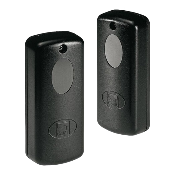
FOTOCELLULE A RAGGI INFRAROSSI
INFRARED PHOTOCELLS
CELLULES PHOTOELECTRIQUES A RAYONS INFRAROUGES
-
INFRAROT
LICHTSCHRANKEN
FOTOCÉLULAS RAYOS INFRARROJOS
3
4
5
CON CONTENITORE DA INCASSO (5)
WITH FLUSH-MOUNTED ENCLOSURE (5)
AVEC BOÎTIER À ENCASTRER (5)
MONTAGEDOSE ZUM EINSETZEN (5)
CON CONTENEDOR EMPOTRADO (5)
P
O
R
T
A
T
A
-
R
A
N
G
E
-
D
R I
1
0
1
0
m
GB
THE PHOTOCELLS WHICH REQUIRES NO SPECIAL ALIGNMENT
Power supply: 12/24V a.c./d.c.
Relay contact range: : : : : 1A max at 24V
Absorption: 60 mA - 24V a.c.
Operating temperature: -20° to 70°C
Dimensions: 46x108 mm; depth 23 mm (Embedded section:
diameter 45 mm; depth 45 mm)
Materials: ABS enclosure / polycarbonate cover
Protection rating: IP54
Conforms to UNI 8612
1) Optoelectronic-circuit enclosure
2) Optoelectronic circuit
3) Cover with incorporated infrared screen
4) Cover fixing screws
5) Fixing base for container (1)
A - Align and fix the photocells at a height of
approximately 50 cm from the ground.
B - Make the necessary arrangements for cable access;
if using the flush-mounted enclosure (5), make a space
in which it may be properly housed.
C - Then fix the container of circuit (1) to the wall or at
the fixing base (5) using the screws provided and adding
any inserts as necessary.
D - Make the necessary connections (see back) and
conclude by fitting the cover with infrared screen (3).
TECHNISCHE DATEN
HAUPTKOMPONENTEN
MONTAGEBESCHREIBUNG
R|
R|
R
BAUREIHE
SERIE
1
P
O
R
T
É
E
-
R
E
C I
H
W
E
T I
E
-
A
L
C
A
N
C
E
D
R I
2
0
D
R I
3
0
2
0
m
3
0
m
TECHNICAL CHARACTERISTICS
MAIN COMPONENTS
ASSEMBLY DESCRIPTION
E
La fotocélula que no require alineamiento
Alimentación: 12/24V a.c./d.c.
Alcance conctatos relés: 1A máx a 24V
Absorbencia: 60 mA - 24V a.c.
Temperatura de funcionamiento: de -20° a +70° C
Dimensiones: 46x108 mm; profundidad 23 mm (parte empotrable: Ø45 mm;
profundidad 45 mm)
Materiales: contenedores de ABS / cubierta de policarbonato
Grado de protección: IP 54
A las normas UNI 8612
1) Contenedor circuito óptico-electrónico
2) Circuito óptico-electrónico
3) Cubierta con pantalla infrarroja integrada
4) Tornillo de fijación cubierta
5) Base de fijación para caja (1)
A - Alinee y fije las fotocélulas a una altura de alrededor de 50 cm desde el
piso.
B - Preparar la llegada de los cables si se utiliza el contenedor empotrado (5),
realizar un alojamiento donde pueda fijarse adecuadamente.
C - Entonces, fije la caja del circuito (1) a la pared o a la base de fijacion (5)
usando los tornillos correspondientes suministrados de serie y añadiendo las
espigas si fuera necesario.
D - Realizar las conexiones necesarias (ver atrás) y, por último, montar la tapa
con pantalla infrarroja (3).
DIR
MISURE DI FISSAGGIO E INGOMBRO
SIZE AND INSTALLATION MEASUREMENTS
MESURES DE FIXATION ET ENCOMBREMENT
ABMESSUNGEN BEFESTIGUNG UND RAUMBEDARF
MEDIDAS DE FIJACION Y DIMENSIONES MAXIMAS
27 mm
46 mm
F
CARACTÉRISTIQUES TECHNIQUES
LA PHOTOCELLULE QUI NE NECESSITE AUCUNE INTERVENTION
POUR L'ALLIGNEMENT
Alimentation: 12/24V c.a./c.c.
Portée contacts relais: 1A max à 24V
Absorption: 60 mA - 24V c.a.
Température de fonctionnement: des -20° à +70°C
Dimensions: 46x108 mm; profondeur 23 mm (partie
emboitable: Ø45 mm; profondeur 45 mm)
Matériaux: boîtiers en ABS / couvercle en polycarbonate
Degré de protection: IP54
A normes NFP 25-362
COMPOSANTS PRINCIPAUX
1) Boîtier circuit optique-électronique
2) Circuit optique-électronique
3) Couvercle avec écran infrarouge incorporé
4) Vis de fixation du couvercle
5) Base de fixation pour boîtier (1)
DESCRIPTION DU MONTAGE
A - Aligner et fixer les photocellules à environ 50 cm du
sol.
B - Prévoir l'arrivée des câbles; préparer un
compartiment où fixer le boîtier à encastrer (5) de façon
appropriée, s'il est utilisé.
C - Fixer ensuite le boîtier du circuit (1) au mur ou à la
base de fixation (5) à l'aide des vis fournies de sèrie et
en ajoutant éventuellement les chevilles.
D - Effectuer les branchements voulus (voir au dos) et
enfin monter le couvercle à écran infrarouge (3).
CARACTERISTICAS TÉCNICAS
COMPONENTES PRINCIPALES
DESCRIPCION DEL MONTAJE
Documentazione
Tecnica
S11
1.2
rev.
03/2000
©
CAME
CANCELLI
AUTOMATICI
119S11
23 mm

Manuels Connexes pour CAME R Série


Sommaire des Matières pour CAME R Série
- Page 1 SERIE Documentazione Tecnica FOTOCELLULE A RAGGI INFRAROSSI rev. INFRARED PHOTOCELLS 03/2000 CELLULES PHOTOELECTRIQUES A RAYONS INFRAROUGES © CAME INFRAROT LICHTSCHRANKEN CANCELLI AUTOMATICI FOTOCÉLULAS RAYOS INFRARROJOS 119S11 MISURE DI FISSAGGIO E INGOMBRO SIZE AND INSTALLATION MEASUREMENTS MESURES DE FIXATION ET ENCOMBREMENT...
- Page 2 Alimentazione 12/24V Connection examples to a CAME switchboard 12/24V power supply Alimentation 12/24V Exemples du branchement sur un tableau électrique CAME Stromversorgung 12/24V Beispiel für den Anschlüß an die Schalttafel CAME Alimentación 12/24V Ejemplos de conexión en el cuadro eléctrico CAME...