Dolmar PB-7601.4 Instructions D'emploi
Table des Matières
Les langues disponibles
Les langues disponibles
Liens rapides
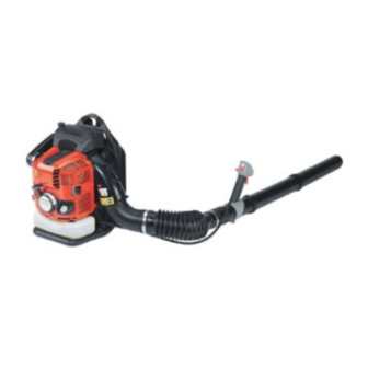
GASOLINE BLOWER
SOUFFLEUR A ESSENCE
SOPRADOR DE GASOLINA
INSTRUCTION MANUAL
INSTRUCTIONS D'EMPLOI
INSTRUCCIONES DE MANEJO
Dolmar CA Statement
PB-7601.4
Dolmar non CA Statement
PB-7600.4
Important:
Read this instruction manual carefully before putting the Blower into operation and
strictly observe the safety regulations! Preserve instruction manual carefully!
Importante:
Lisez attentivement ce manuel utilisateur avant de mettre en route le souffleur et
respectez scrupuleusement les consignes de sécurité.
Conservez soigneusement ce manuel.
Importante:
Lea bien este manual antes de poner el soplador en funcionamiento, y observe
estrictamente las medidas de seguridad. Conserve este manual de instrucciones.
English / Français / Spanish
Chapitres
Table des Matières
Dépannage

Manuels Connexes pour Dolmar PB-7601.4


Sommaire des Matières pour Dolmar PB-7601.4
- Page 1 GASOLINE BLOWER SOUFFLEUR A ESSENCE SOPRADOR DE GASOLINA Dolmar CA Statement PB-7601.4 Dolmar non CA Statement PB-7600.4 INSTRUCTION MANUAL Important: Read this instruction manual carefully before putting the Blower into operation and strictly observe the safety regulations! Preserve instruction manual carefully! INSTRUCTIONS D’EMPLOI...
-
Page 28: Symboles
Symboles ..................28 Consignes de sécurité ............29-31 Les modèles PB-7600.4 / PB-7601.4 légers, pratiques et compacts, Caractéristiques techniques ............32 allient les avantages d’une technologie de pointe à une conception Liste des pièces ................. 33 ergonomique et sont des outils de professionnels pour de nombreuses Instructions de montage ............ -
Page 29: Consignes De Sécurité
CONSIGNES DE SECURITE Généralités • Pour tirer le meilleur parti de votre machine, vous devez lire, assimiler et respecter les instructions figurant dans ce manuel (1). Les utilisateurs mal informés risquent, par des manipulations inappropriées, de se blesser ou de blesser leur entourage. •... - Page 30 Avant de mettre la machine en marche, assurez-vous que toutes les instructions sont bien respectées. N’utilisez pas d’autres méthodes de mise en marche de l'appareil (6). • N’utilisez la machine et les outils fournis que pour les applications spécifiées. • Ne mettez la machine en marche que lorsque tous les accessoires ont été...
-
Page 31: Premiers Secours
N’utilisez-que des pièces et des accessoires d’origine, fournis par DOLMAR. L'utilisation d’outils et d’accessoires non agréés augmente les risques d’accident. DOLMAR décline toute responsabilité en cas d’accident ou de dommage provoqué par l’utilisation d’accessoires ou d’outils non agréés. -
Page 32: Caractéristiques Techniques
Bougie NGK CMR6A Distance entre électrodes (mm) 0.7 - 0.8 Niveau de bruit (15 metres par ANSI B175-2-2000 (dB(A)) Notes: 1. Utiliser l’huile et la bougie désignés par DOLMAR. 2. La spécification peut être soumise à changement sans avis préalable. -
Page 33: Liste Des Pièces
LISTE DES PIÈCES Optionnel Désignation des pièces Désignation des pièces Désignation des pièces Désignation des pièces 1. Interrupteur d’arrêt 8. Levier d’étrangleur 15. Capot de bougie 22. Tube de souffleur 2. Poignée de contrôle 9. Poignée de démarrage 16. Bougie 23. -
Page 34: Instructions De Montage
INSTRUCTIONS DE MONTAGE Montage du tube de soufflante ATTENTION : Avant toute opération sur le souffleur, coupez toujours le moteur et débrancher les connecteurs de bougie. Portez toujours des gants de protection! ATTENTION: Ne mettre le souffleur en marche que lorsqu’il est complètement monté. -
Page 35: Fixation De La Bandoulière
Fixation de la bandoulière Procédure de fixation Fixation de la bandoulière au souffleur. • Passez le bout de la bandoulière dans la fente de suspension en le passant par le bas tel qu'indiqué dans la figure à droite. Le côté de la bandoulière avec le bout plié... -
Page 36: Avant De Démarrer Le Moteur
(Se reporter à la P. 41 pour la procédure et la fréquence de Limite inférieur changement d’huile) Huile recommandée : Huile originale Dolmar ou Huile SAE10W-30 de type API et qualité SF ou supérieure (Huile à moteur à 4 temps pour automobiles) Capacité d’huile : Environ 0,22 L (220 ml) Précaution... -
Page 37: Alimentation En Carburant
2. Alimentation en carburant AVERTISSEMENT • Lors de l’alimentation en carburant, s’assurer que les instructions suivantes sont respectées pour éviter l’inflammation ou l’incendie: − L’alimentaion en carburant doit être effectuée à l’endroit où il n’y a pas de feu. Ne jamais apporter du feu (tabac, etc.) près de l’endroit de l’alimentaion en carburant. -
Page 38: Fonctionnement
FONCTIONNEMENT 1. Mise en marche AVERTISSEMENT • Ne jamais tenter de démarrer le moteur dans l’endroit où le carburant a été alimenté. Le démarrage du moteur doit s’effectuer en maintenant une distance de 3 m au moins. − Sinon, l’inflammation ou l’incendie peut se provoquer. •... -
Page 39: Réglage Du Ralenti
NOTE • Le moteur pourra être endommagé si le levier d’étrangleur est déplacé au-delà de la position “CLOSE”. • Si le moteur s’arrête avec un bruit d’explosion ou si le moteur a démarré, mais s’est arrêté avant la manoeuvre de le levier d’étrangleur, remettre ce levier à... -
Page 40: Mode Opératoire
MODE OPERATOIRE 1. Réglage de la bandoulière Pour déserrer les bandoulières Pour serrer les bandoulières Réglez les bandoulières à la longueur adéquate vous permettant de porter le souffleur confortablement pour travailler. Réglez les bandoulières tel qu’indiqué sur la figure. Réglage du levier du régulateur Déplacez la poignée de contrôle le long du tube rotatif sur la position la plus confortable. -
Page 41: Inspection Et Maintenance
INSPECTION ET MAINTENANCE DANGER • Avant l’inspection et la maintenance, arrêter le moteur et le laisser refroidir. Enlever également la bougie d’allumage et le capot de bougie. − Si l’inspection ou la maintenance est effectuée immédiatement après l’arrêt du moteur ou avec le capot en place, l’opérateur a un risque d’être brûlé... -
Page 42: Nettoyage Du Filtre À Air
2. Nettoyage du filtre à air Boulon du couvercle DANGER DEFENSE DE FAIRE DU FEU Couvercle de l’élément Intervalle de nettoyage et de contrôle : Quotidien (toutes les 10 heures de marche) (1) Desserrer le boulon du couvercle. (2) Retirer le couvercle du filtre à air. (3) Retirer l'élément et nettoyer toute salissure avec la brosse. -
Page 43: Nettoyage Du Filtre À Carburant
4. Nettoyage du filtre à carburant • Le filtre à carburant colmaté peut causer un démarrage difficile ou une défaillance de la montée de vitesse du moteur. • Vérifier régulièrement le filtre à carburant comme ce qui suit: (1) Démonter le bouchon de vidange du réservoir de carburant, évacuer le carburant pour vider le réservoir. -
Page 44: Localisation Des Défauts
Localisation des défauts Défaut système Observation Cause Pas de démarrage du Système d'allumage Étincelle d'allumage Défaut dans l'alimentation en carburant ou dans le systèm de moteur ou démarrage difficile présente compression. Défaut mécanique Pas d'étincelle Interrupteur d'arrêt actionné, défaut du fil ou court-circuit, d'allumage bougie d'allumage ou connecteur défectueux, module d'allumage défectueux... -
Page 45: Dépannage
DEPANNAGE Avant de faire une demande de réparations, vérifier un inconvénient par soi-même. S’il y a aucune anomalie, régler votre machine suivant la description de ce manuel. Ne jamais manipuler ou déposer aucune partie contrairement à la description. Pour les réparations, s’adresser à l’agent du service après-vente habilité. - Page 46 GARANTIE LIMITÉE D’UN AN MAKITA Politique de garantie Chaque outil Makita est inspecté rigoureusement et testé avant sa sortie d’usine. Nous garantissons qu’il sera exempt de défaut de fabrication et de vice de matériau pour une période d’UN AN à partir de la date de son achat initial.
- Page 66 DOLMAR GmbH Postfach 70 04 20 D-22004 Hamburg Germany 6679501200 07.09...