Napoleon Vector Série Manuel D'installation
Masquer les pouces
Voir aussi pour Vector Série:
- Manuel d'installation (156 pages) ,
- Manuel du propriétaire (81 pages) ,
- Manuel du propriétaire (80 pages)
Table des Matières
Les langues disponibles
Les langues disponibles
Liens rapides
NATURAL GAS MODELS:
PROPANE GAS MODELS:
SAFETY INFORMATION
WARNING
!
FIRE OR EXPLOSION HAZARD
Failure to follow safety warnings exactly
could result in serious injury, death, or
property damage.
- Do not store or use gasoline or other
fl ammable vapors and liquids in the vicinity of
this or any other appliance.
- WHAT TO DO IF YOU SMELL GAS:
•
Do not try to light any appliance.
•
Do not touch any electrical switch; do not
use any phone in your building.
•
Immediately call your gas supplier from a
neighbour's phone. Follow the gas
supplier's instructions.
•
If you cannot reach your gas supplier, call
the fi re department.
- Installation and service must be
performed by a qualifi ed installer, service
agency, or the supplier.
This appliance may be installed in an aftermarket,
permanently located, manufactured home (USA
only) or mobile home, where not prohibited by
local codes.
This appliance is only for use with the type of gas
indicated on the rating plate. This appliance is
not convertible for use with other gases, unless
a certifi ed kit is used.
INSTALLER:
Leave this manual with the appliance
CONSUMER:
Retain this manual for future reference
Wolf Steel Ltd., 24 Napoleon Rd., Barrie, ON, L4M 0G8 Canada / 103 Miller Drive, Crittenden, Kentucky, USA, 41030
$10.00
LV38N-1 / LV50N-2 / LV62N / LV74N / LV38N2-1 / LV50N2-2 / LV62N2 / LV74N2
ADD PRODUCT CODE HERE (TRADE GOTHIC LT STD FONT)
LV38P-1 / LV50P-2 / LV62P / LV38P2-1 / LV50P2-2 / LV62P2
INSTALLATION MANUAL
Phone 1 (866) 820-8686 • www.napoleon.com • hearth@napoleon.com
ADD MANUAL TITLE
THIS APPLIANCE IS SUITABLE FOR THE OPTIONAL DYNAMIC
(See Dynamic Heat Control™ installation manual)
CERTIFIED TO THE CANADIAN AND AMERICAN NATIONAL STANDARDS:
CSA 2.22 AND ANSI Z21.50 FOR VENTED DECORATIVE GAS APPLIANCES
CERTIFIED TO THE CANADIAN AND AMERICAN NATIONAL STANDARDS:
CSA 2.22 AND ANSI Z21.50 FOR VENTED DECORATIVE GAS APPLIANCES
IF INSTALLATION + OPERATION, ADD SERIAL
CSA /
INTERTEK
BARCODE LABEL ON THE OWNER'S MANUAL"
LOGO
Product Name / Code
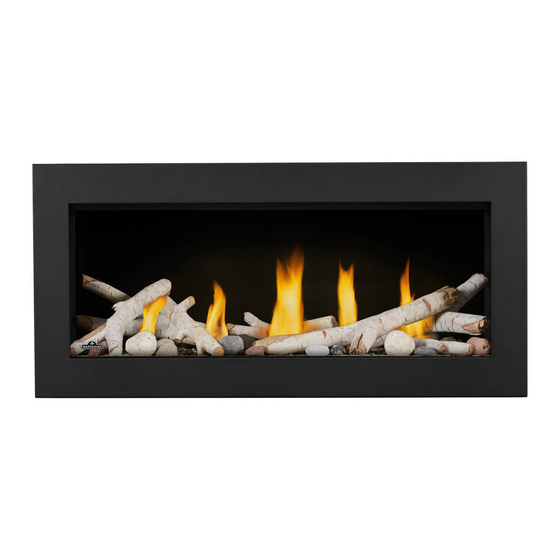
Vector™ Series
(MUST use title from Price Book)
ADD ____ ILLUSTRATED
ADD PRODUCT IMAGE
HEAT CONTROL™ SYSTEM
FOR INDOOR USE ONLY
FOR INDOOR USE ONLY
NUMBER LABEL HERE
PLACE BARCODE LABEL ON THE
IF SEPARATE MANUALS, ADD "PLACE
OWNER'S MANUAL
ENGLISH
FRENCH PG. 75
(LV38-1 illustrated)
H H EAT CONT
T CONTROL OL
TM
PATENT PENDING
W415-1709 / D / 06.14.19
Chapitres
Table des Matières

Manuels Connexes pour Napoleon Vector Série


Sommaire des Matières pour Napoleon Vector Série
- Page 74 NAPOLEON CELEBRATING OVER 40 YEARS OF HOME COMFORT PRODUCTS 7200, Route Transcanadienne, Montréal, Québec H4T 1A3 24 Napoleon Road, Barrie, Ontario, Canada L4M 0G8 214 Bayview Drive, Barrie, Ontario, Canada L4N 4Y8 103 Miller Drive, Crittenden, Kentucky, USA 41030 Phone: 1-866-820-8686...
- Page 75 LE MANUEL DU PROPRIÉTAIRE LOGO BARCODE LABEL ON THE OWNER’S MANUAL” Wolf Steel Ltd., 24 Napoleon Rd., Barrie, ON, L4M 0G8 Canada / 103 Miller Drive, Crittenden, Kentucky, USA, 41030 Téléphone 1(866)820-8686 • www.napoleon.com • hearth@napoleon.com W415-1709 / D / 06.14.19...
-
Page 76: Consignes De Sécurité
consignes de sécurité AVERTISSEMENT • Cet appareil est chaud lorsqu’il AVERTISSEMENT fonctionne et peut causer de graves brûlures en cas de contact. • Toute modifi cation apportée à cet appareil ou aux contrôles peut être LA VITRE CHAUDE CAUSERA dangereux et est interdit. DES BRÛLURES. - Page 77 consignes de sécurité AVERTISSEMENT • N’utilisez pas une souffl erie intégrée, un échangeur de chaleur intégré ni un autre accessoire non approuvé pour cet appareil. • Cet appareil ne doit pas être raccordé au conduit d’une cheminée desservant un autre appareil de chauffage à...
- Page 78 table des matières information générales branchement du gaz taux et effi cacités opération vue d’ensemble d’installation installation des pattes de cloutage emplacement de la plaque d’homologation / des instructions d’allumage 10.0 encadrement fini - après installation dans une maison mobile liste de piéces l’installation de l’appareil installation / retrait des poignées de...
-
Page 79: Information Générales
information générales Installateur: veuillez remplir la liste de contrôle de l’appareil dans le manuel du propriétaire. 1.0 information générales Lorsque l’appareil est installé à une altitude de plus de 4 5000 pieds (1372m) et en l’absence de recommandations particulières de l’autorité compétente locale, l’indice certifi é du débit à haute altitude devra être réduit au taux de 4% pour chaque 1 000ft (305m) supplémentaire. -
Page 80: Taux Et Effi Cacités
information générales taux et effi cacités LV38-1 Un Seul Côté Voir à Travers Type d’appareil LV38N-1 LV38P-1 LV38N2-1 LV38P2-1 Type de Comburant Gaz Naturel Propane Gaz Naturel Propane Altitude (PI) 0-4 500 Débit max. (BTU/h) 30 000 28 000 30 000 28 000 Débit min. -
Page 81: Vue D'ensemble D'installation
information générales information générales vue d’ensemble d’installation Étapes d’installation recommandés: 1. Déterminer les exigences de ventilation avant de décider de l’emplacement fi nal de l’appareil 2. Planifi er l’enceinte, l’encadrement, les façades, les accessoires, etc. 3. Installez un encadrement brut (voir la section « encadrement approximatif »). 4. - Page 82 information générales AVERTISSEMENT • Allumez toujours la veilleuse, que ce soit pour la première fois ou lorsque l’approvisionnement en gaz est épuisé, avec la porte vitrée ouverte ou retirée. • Prévoyez un accès suffi sant pour entretenir et opérer l’appareil. •...
-
Page 83: Emplacement De La Plaque D'homologation / Des Instructions D'allumage
être préfabriquée ou mobile (É.U. seulement) installée Vertical vent 1” Conduit d’évent vertical 1” L’appareil doit être ventilé à l’aide de l’ensemble d’évacuation propre à Napoleon. Référez au qualifié pour le gaz, un Remplacement du panneau **Mantel 12”... -
Page 84: Installation Dans Une Maison Mobile
information générales installation dans une maison mobile Cet appareil doit être effectuée en respectant les directives du fabricant et le Manufactured Home Construction and Safety Standard, Title 24 CFR, Part 3280, aux États-Unis, ou les normes actuelles pour les maisons mobiles, CAN/CSA Z240 SÉRIE MH au Canada. -
Page 85: Dimensions
2.0 dimensions dimensions un seul côté Base du collier d'air 41 3/16" 1046mm 32 3/4" 39 11/16" 18 5/8" 832mm 1008mm ECRAN DE PROTECTION 473mm 8 1/16" 7 1/16" 205mm 179mm 3 1/8" 80mm 19 7/8" 1/2” 505mm [12.7mm] Ø 8" 203mm Ø... -
Page 86: Voir À Travers
dimensions voir à travers Base du collier d'air 41 3/16" 1046mm 39 11/16" 1008mm 32 3/4" 18 5/8" 832mm ECRAN DE PROTECTION 473mm 8 1/16" 7 1/16" 205mm 179mm 3 1/8" 80mm 16 3/16" 1/2" 411mm Ø 8" 1/2" [12.7mm] [12.7mm] 203mm Ø... -
Page 87: Exigences Minimum D'évacuation
exigences minimum d’évacuation 3.0 exigences minimum d’évacuation AVERTISSEMENT • Risque d’incendie. Conservez les dégagements nécessaires au conduit d’évent et à l’appareil. • Les courses horizontales et verticales du système doivent être supportées à tous les 3 pi (0,9m). Utilisez l’ensemble de support mural Wolf Steel W010-0067 ou des supports incombustibles équivalents afi n de conserver le dégagement minimal aux matériaux combustibles pour les courses verticales et horizontales. - Page 88 exigences minimum d’évacuation Utilisez uniquement des composants d’évacuation Wolf Steel, Simpson Dura-Vent, Selkirk Direct Temp, American Metal Americent ou Metal-Fab. Les minimums et maximums des longueurs d’évent, pour les installations verticales et horizontales, et les emplacements des terminaisons pour les deux systèmes sont précisés dans ce manuel et doivent être respectés.
-
Page 89: Installations Typiques D'évents
exigences minimum d’évacuation installations typiques d’évents 18" (45.7cm) maximum LV38-1 & LV50-2: 62 3/4” (159.4cm) 30” LV38-1 & LV50-2: 30” (76.2cm) min la pente min plus (76.2cm) LV62 & LV74: 48” (121.9cm) min LV62 & LV74: 80 3/4” (205.1cm) minimum la pente min plus 62 3/4"... -
Page 90: Un Seul Côté Ou Voir À Travers
exigences minimum d’évacuation UN SEUL CÔTÉ OU VOIR À TRAVERS 16" (40.6cm) note: Une élévation verticale minimale de 6’ (1,83m) tient compte des dimensions minimales pratiques 40 ft (12m) pour l’enceinte spécifi que de l’appareil et d’une structure mini- 6’ (1.83m) male de construction. -
Page 91: Emplacements Et Dégagements Minimaux De La Terminaison
exigences minimum d’évacuation 3.2 emplacements et dégagements minimaux de la terminaison W415-1709 / D / 06.14.19... -
Page 92: Terminaison Horizontale (Gaz Naturel)
exigences minimum d’évacuation terminaison horizontale (gaz naturel) LV38-1 / LV50-2 / LV62 / LV74 UN SEUL CÔTÉ LV38-1 / LV50-2 VOIR À TRAVERS (GAZ NATUREL SEULEMENT) 40’ V+H≤ 40 ft. (Pour les courses d’évacuation plus longues, V+H ≤ 40 ft. (For longer vent runs, a power un évent de puissance est nécessaire) 38 1/2’... -
Page 93: Lv62 / Lv74 Voir À Travers (Gaz Naturel Seulement)
exigences minimum d’évacuation LV62 / LV74 VOIR À TRAVERS (GAZ NATUREL SEULEMENT) V+H≤ 40 ft. (Pour les courses d’évacuation plus longues, 40’ V+H ≤ 40 ft. (For longer vent runs, a power un évent de puissance est nécessaire) vent is required). 38 1/2’... - Page 94 exemple d'exigences d'évacuation - gaz naturel 40’ V = V = 8 ft (GAZ NATUREL SEULEMENT) H = H = 10 ft (GAZ NATUREL SEULEMENT) 30’ 90° 20’ 90° 1-3 elbow zone 1-3 elb b o b w z w zo z ne 1-3 Zone de coude 15’...
-
Page 95: Exigences D'évacuation
exigences d'évacuation terminaison verticale (gaz naturel) TOUS LES APPAREILS (GAZ NATUREL SEULEMENT) V+H≤ 40 ft. (Pour les courses d’évacuation plus V+H ≤ 40 ft. (For longer vent runs, 40’ longues, un évent de puissance est nécessaire) a power vent is required). H ≤20 ft. -
Page 96: Toutes Terminaisons (Propane) Lv38
exigences d'évacuation - propane toutes terminaisons (propane) LV38-1 (PROPANE SEULEMENT) V+H ≤ 40 pi. H ≤ 10 pi. 40’ (Pour les courses horizontales lon- 38 1/2’ gueurs, un terminaison mécanique (462”) est requis). V + H sont mesurés du centre à partir du centre centre des coudes d’évents. -
Page 97: Toutes Terminaisons (Propane ) Lv50-2 / Lv62
exigences d'évacuation - propane toutes terminaisons (propane ) LV50-2 / LV62 (PROPANE SEULEMENT) 40’ 38 ½’ V+H ≤ 40 pi. H ≤ 4⅜ pi. (462”) (Pour les courses horizontales longueurs, un termi- naison mécanique est requis). 35’ V + H sont mesurés du centre à partir du centre centre des coudes d’évents. - Page 98 encadrement approximatif - avant l’installation de l’appareil 4.0 encadrement approximatif - avant l’installation de l’appareil note: Lorsque vous installez les accessoires de fi nition optionelles, les dimensions de l’ossature et les matériaux de fi nition peuvent différer de ce qui est décrit dans ces instructions ci-dessous, voir les instructions fournies dans le trousse de l’accessoire pour les spécifi...
-
Page 99: Encadrement Approximatif - Avant L'installation De L'appareil
encadrement approximatif - avant l’installation de l’appareil dimensions minimales de l’encadrement 1” (2.54cm) min. 6” (15.2cm) min. Ne placez pas d’objets devant Do not put objects in front of the l’appareil (distance minimale de 48 po appliance (minimum distance of 4 feet) [121,9cm]). -
Page 100: Dégagements Minimaux De L'enceinte
encadrement approximatif - avant l’installation de l’appareil 4.1.1 dégagements minimaux de l’enceinte note: un seul côté Les composants ombrés (encadrement de fi nition) doivent être des matériaux incombustibles. 3” [76mm] (minimum chaque côtés pour les sections d’évacuation horizontale) dehors de 1”... - Page 101 encadrement approximatif - avant l’installation de l’appareil note: Voir à travers Les composants ombragés doivent être des matériaux incombustibles. 1” [25mm] minimum tous les côtés pour les sections 3” [76mm] (minimum chaque côté pour les section d’évacuation verticale. d’évacuation horizontale) dehors de l’enceinte. 2”...
- Page 102 encadrement approximatif - avant l’installation de l’appareil Avant d’encadrer votre appareil, déterminez les exigences de ventilation avant de décider de l’emplacement fi nal de l’appareil. Après un encadrement brut, placez l’appareil dans sa position fi nale. un seul côté Avant d’encadrer l’appareil, assurez-vous d’installer l’espaceur coupe-feu.
-
Page 103: Installation D'évacuation
5.0 installation d’évacuation installation d'évacuation AVERTISSEMENT • Avant d’effectuer les branchements pour l’alimentation en gaz et électronique, assurez-vous de retirer toute composante non fi xée à l’intérieur de la chambre de combustion. • Si votre appareil comprend un système de télécommande, assurez-vous que le récepteur est à la position «... - Page 104 installation d'évacuation 4. Enlevez la douille d’évent comme illustré et assurez-vous de fi xer les extrémités ensemble (Fig- ure 4). 5. Assurez-vous que les deux extrémités s’alignent et fi xez les extrémités avec des agrafes et des attaches (Figure 5). Fig.
-
Page 105: Installation Horizontale
installation d'évacuation installation horizontale AVERTISSEMENT • L’espaceur coupe-feu doit être installé avec l’écran protecteur orienté vers le haut. • La terminaison ne doit pas être enchâssée dans le mur ou le revêtement extérieur plus que l’épaisseur de la bride de la plaque de montage. PROTECTEUR Cette confi... -
Page 106: Utilisation De Composants Fl Exibles D'évacuation
installation d'évacuation utilisation de composants fl exibles d’évacuation AVERTISSEMENT • Ne laissez pas la gaine fl exible se tasser contre les courses horizontales ou verticales et les coudes. Gardez-la tendue. • Des espaceurs sont fi xés à la gaine fl exible à intervalles prédéterminés afi n de garder un espace vide avec le conduit extérieur. -
Page 107: Installation De La Terminaison Verticale
installation d'évacuation 5.4.2 installation de la terminaison verticale AVERTISSEMENT • Conservez un espace minimale de 2 po (51mm) entre la base de la prise d’air et le collet de solin. Matériel de fi xation fourni avec les ensembles de terminal pour toit et raccord appropriées. Fixez le support de toit au toit à... -
Page 108: Renstreignants D'évents Verticaux
installation d'évacuation renstreignants d’évents verticaux Certaines confi gurations d’évacuation verticales peuvent avoir une fl amme très active. Si cette apparence n’est pas désirée, la sortie du conduit d’évacuation peut être réduite en utilisant une plaque de restriction approuvée par Wolf Steel. Cet ensemble n’est pas recommandé pour les courses verticales courtes. Selon l’année et le modèle de votre appareil, il se peut que celui-ci ne soit pas muni de trous de fi... -
Page 109: Installation De Bouclier D'évent
installation d'évacuation installation de bouclier d’évent important: Pour faciliter l’installation, le cadre supérieur avant peut être enlever. Le cadre supérieur avant doit être réinstaller avant d’installer les pattes de cloutages. note: Le bouclier d’évent est télescopique et doit être réglé pour protéger les 30 premiers pouces verticaux éventuels. -
Page 110: Information Électriques
information électriques 6.0 information électriques branchement par câble Vous devez effectuer un branchement par câble avec cet appareil. Une charpente permanente servant à encastrer l’appareil nécessite un branchement par câble de la boîte de dérivation de l’appareil. Cet appareil doit être raccordé électriquement et mis à la terre conformément aux codes locaux. -
Page 111: Installation Du Support / Interrupteur De Batterie
information électriques installation du support / interrupteur de batterie Installez le support / interrupteur de batterie dans un boîtier électrique standard. Déterminez un emplacement approprié et installez le boîtier électrique. note: Assurez-vous que l’interrupteur est en position « REMOTE » (milieu). première initialisation de la télécommande / bloc-piles note: La procédure d’initialisation doit être complétée en moins de 10 secondes après que le bouton réinitialisaition/... -
Page 112: Accès Aux Contrôles
information électriques accès aux contrôles AVERTISSEMENT • N’utilisez pas cet appareil si une partie quelconque a été submergée. Contactez immédiatement un technicien de service qualifi é pour inspecter l’appareil pour des dommages au circuit électrique. • Risque de chocs électriques ou d’explosion. Ne branchez pas le 110 V à la soupape ou à l’interrupteur mural de l’appareil. -
Page 113: Schéma De Câblage
information électriques schéma de câblage AVERTISSEMENT • Ne raccordez pas l’interrupteur mural ou la soupape de gaz à l’alimentation électrique (110V). note: Pour votre protection contre les risques de chocs électriques, cet appareil est muni d’une fi che à trois broches et devrait être branché... -
Page 114: Lv38 / Lv50-2 Schéma De Câblage
information électriques 6.8.1 LV38 / LV50-2 schéma de câblage LAMP COMFORT W415-1709 / D / 06.14.19... -
Page 115: Lv62 / Lv74 Schéma De Câblage
information électriques 6.8.2 LV62 / LV74 schéma de câblage W415-1709 / D / 06.14.19... -
Page 116: Branchement Du Gaz
information électriques 7.0 branchement du gaz AVERTISSEMENT • Risque d’incendie, d’explosion, ou d’asphyxie. Assurez-vous qu’il n’y ait aucune source d’allumage comme des étincelles ou une fl amme nue. • Soutenez le contrôle du gaz lorsque vous attachez le tuyau pour éviter de plier la conduite de gaz. •... -
Page 117: Opération
information électriques 8.0 opération AVERTISSEMENT • Si ces instructions ne sont pas suivies à la lettre, un incendie ou une explosion pourraient s’ensuivre, causant des dommages matériels, des blessures corporelles ou des pertes de vie. • Si applicable, allumez toujours la veilleuse, que ce soit pour la première fois ou lorsque l’approvisionnement en gaz est épuisé, avec la porte vitrée ouverte ou retirée. -
Page 118: Installation Des Pattes De Cloutage
nailing tab installation 9.0 installation des pattes de cloutage important: Si le cadre supérieur avant a été enleverm il doit être réinstallez avant d’installer les pattes de cloutage. Alignez les pattes de cloutage avec les trous de Retirer les deux vis de l’appareil. l’appareil, fi... -
Page 119: Encadrement Avec Des Matériaux Incombustibles
10.0 encadrement fi ni - après l’installation de l’appareil encadrement fi ni - après l'installation de l'appareil 10.1 encadrement avec des matériaux incombustibles Chasse d’un seul côté note: Les composants ombrés (encadrement de fi nition) doivent être des matériaux incombustibles. Les composants ombragés (cadrage de fi... -
Page 120: Encadrement Fi Ni - Après L'installation De L'appareil
encadrement fi ni - après l'installation de l'appareil note: Recouvert d’un seul côté Les composants ombrés (encadrement de fi nition) doivent être des matériaux incombustibles. Les composants ombragés (cadrage de fi nition) doivent être installés après que l’appareil a été placé... - Page 121 encadrement fi ni - après l'installation de l'appareil Voir à travers note: Plafond Les composants ombrés (encadrement de fi nition) doivent être des matériaux incombustibles. Les composants ombragés (cadrage de fi nition) doivent être installés après que l’appareil a été placé...
-
Page 122: Voir À Travers Encastré
encadrement fi ni - après l'installation de l'appareil Voir à travers encastré note: Plafond Les composants ombrés (encadrement de fi nition) doivent être des matériaux incombustibles. Les composants ombragés (cadrage de fi nition) doivent être installés après que l’appareil a été placé... -
Page 123: Restriction De Placement Des Attaches
11.0 fi nitions fi nitions AVERTISSEMENT • Risque d’incendie! • N’obstruez jamais l’ouverture sur le devant de l’appareil. • Si la fi nition de la façade de l’appareil est fait, elle doit être faite de matériau incombustible comme de la brique, du marbre du granite, etc., sous réserve que ces matériaux ne dépassent pas le dimension spécifi... -
Page 124: Fi Nition Avec Les Matériaux Incombustibles
fi nitions 11.2 fi nition avec les matériaux incombustibles La fi nition incombustible est requis. 15 5/8” (39.7cm) 18 1/2” (47.1cm) 7” (17.9cm) LV38-1 LV50-2 LV62 LV74 54 3/4” (139.1cm) 66 3/4” (169.5cm) 78 3/4” (200cm) 90 3/4” (230.5cm) LA ZONE NON SOMMAIRE DOIT ÊTRE MATÉRI- AUX NON COMBUSTIBLES. -
Page 125: Vue De Côté
fi nitions AVERTISSEMENT • Le matériau de fi nition incombustible serré sur le châssis autour du cadre de la barrière de protection (PSB) ne doit pas dépasser plus de 4“ (10cm) de la face de la barrière de sécurité (au-dessus de la porte et des côtés seulement). -
Page 126: Installation De Matériau Incombustible
fi nitions 11.3 installation de matériau incombustible AVERTISSEMENT • La surface au-dessus l’appareil devient très chaude. Si des matériaux de fi nition inadéquats sont utilisés, des craquelures peuvent apparaître. • Voir la section «restriction de placement des attaches ». Des vis plus longues peuvent endommager la conduite de gaz et / ou les composants internes. -
Page 127: Dégagements Minimaux De La Tablette Combustible
fi nitions 11.4 dégagements minimaux de la tablette combustible AVERTISSEMENT • Risque d’incendie. Maintenir tous les espaces spécifi és pour les espaces combustibles. Le non-respect de ces instructions peut provoquer un incendie ou provoquer une surchauffe de l’appareil. Assurez-vous que tous les dégagements (c’est-à-dire le dos, le côté, le haut, l’évent, le manteau, l’avant, etc.) sont clairement maintenus. -
Page 128: Restrictions Pour Monter Un Téléviseur (Sans Dhc Md )
fi nitions 11.5 restrictions pour monter un téléviseur (sans DHC Installation partiellement enchâssées avec un Installation affleurant sans un manteau manteau 6” min. Support du Support du téléviseur téléviseur 2,5” min. 2” min. (3” max. recommendée) Enceinte Enceinte Haut de la bride de Haut de la finition (ouverture de bride de... -
Page 129: Installation / Enlèvement De La Barrière De Protection
fi nitions 11.6 installation / enlèvement de la barrière de protection Pour enlever la barrière de protection de l’appareil, soigneusement soulevez-la hors des vis d’épaulement. Placez la barrière de protection sur l’appareil en le soulevant et en l’accrochant sur les vis à épaulement situées sur le côté. - Page 130 fi nitions note: Assurez-vous que la porte ouvre et ferme librement scellé. LV38-1 Illustré IMPORTANT: Une fois que les loquets sont engagés, test pour assurer que la porte est en place et ne tombera pas. ARRIÈRE - VOIR À TRAVERS SEULEMENT Retirez les vis qui fixent la porte à...
-
Page 131: Installation Des Braises Vitrifi Ées
fi nitions 11.8 installation des braises vitrifi ées AVERTISSEMENT • Nettoyez les braises vitrifi ées avant d’installation. Assurez-vous qu’elles sont sèches avant de les disposer dans le plateau. • Ne changez pas ou ni substituez pas les braises vitrifi ées fournies avec cet appareil. En cas de remplacement, n’utilisez que les braises vitrifi... -
Page 132: Placement Des Composants Décoratif Optionnel
fi nitions 11.9 placement des composants décoratif optionnel Modèles de gaz naturel seulement: Les composants décoratif devrait être installer également à travers le plateau du brûleur mais pas directement sur les orifi ces des brûleurs. Ne jamais place les composants décoratif directement sur les orifi... -
Page 133: Renstreignant Des Évents Verticaux
fi nitions 12.0 ajustements 12.1 renstreignant des évents verticaux Certaines confi gurations d’évacuation verticales peuvent avoir une fl amme très active. Si cette apparence n’est pas désirée, la sortie du conduit d’évacuation doit être réduite en utilisant une plaque de restriction. Pour obtenir l’ensemble approprié, voir la section «... -
Page 134: Réglage De La Veilleuse
fi nitions 12.3 réglage de la veilleuse Ajustez la vis de la veilleuse pour obtenir une fl amme de taille normale. Tournez vers la droite pour réduire l’apport de gaz. Vérifi ez la pression: Pour vérifi er la pression d’arrivée, tournez la vis (A) vers la gauche deux à... -
Page 135: Entretien
entretien 13.0 entretien AVERTISSEMENT • Coupez l’alimentation en gaz et l’alimentation électrique avant de procéder à l’entretien de l’appareil. • L’appareil peut être chaud. Attendez qu’il soit refroidi avant d’en faire l’entretien. • N’utilisez pas de produits abrasifs. • Ne peinture pas l’assemblage de la veilleuse. Cet appareil et son système d’évacuation devraient être inspectés avant la première utilisation et au moins une fois l’an par un technicien de service qualifi... -
Page 136: Entretien Annuel
entretien 13.1 entretien annuel AVERTISSEMENT • Le caisson devient trés chaud lors du fonctionnement. Laissez l’appareil se refroidir complétement ou portez des gants antichaleur avant d’effectuer l’entretien. • Ne jamais aspirer des braises qui sont chaudes. • Ne peinturez pas l’assemblage de la veilleuse. •... -
Page 137: Enlèvement Du Brûleur
entretien 13.3 enlèvement du brûleur Enlever l’assemblage de l’écran de protection et la porte, référer aux sections « installation / enlèvement de le la barrière de protection » et « installation / enlèvement de la porte » pour plus de détails. Enlever les composants décoratifs de l’appareil. -
Page 138: Enlèvement Du Module De Contrôle
entretien Débranchez le raccord fl exible de la soupape. Enlevez les fi ls de connexion à la soupape en les identifi ant pour faciliter le rebranchement. Retirez les vis du support de la soupape et enlevez la soupape. Réinstallez toutes les composants avant de faire fonctionner l’appareil. Vérifi... -
Page 139: Remplacement Del
entretien 13.6 remplacement DEL Cet appareil est équipé de nos lumières DEL. Si vous devez remplacer les lumières DEL, suivez les instructions suivantes. Coupez l’alimentation électrique. Retirez la barrière de protection et la porte vitrée, référer aux sections « installation / enlèvement de la barrière de protection »... -
Page 140: Remplacement De La Vitre / Porte
entretien 13.7 remplacement de la vitre / porte AVERTISSEMENT • N’utilisez pas de matériaux de substitution. • La vitre peut étre chaude, ne touchez pas la vitre jusqu’à ce qu’elle ait refroidi. • Usez de prudence lorsque vous enlevez et jetez des débris de verreou des composants endommagés. Assurez-vous d’aspirer tous les débris deverre à... -
Page 141: Rechanges
14.0 rechanges rechanges AVERTISSEMENT • Omettre de positionner les pièces conformément à ce manuel ou d’utiliser uniquement des pièces spécifi quement approuvées pour cet appareil peut causer des dommages matériels ou des blessures corporelles. Contactez votre détaillant pour les questions concernant les prix et la disponibilité des pièces de remplace- ment. -
Page 142: Vue D'ensemble
rechanges 14.1 vue d’ensemble Ces articles peut différer de celle illustré Réf. Description . de pièce En Stock LV38-1 LV50-2 LV62 LV74 Écran de protection (Prime) W565-0279-SER W565-0248-SER W565-0277-SER W565-0276-SER Barrière de protection W010-4147-SER W010-4146-SER W010-4145-SER W010-4144-SER Assemblage de la porte fi xée W010-4198-SER W010-4162-SER W010-4202-SER... -
Page 143: Composants Du Brûleur
rechanges 14.2 composants du brûleur Ces articles peut différer de celle illustré. W415-1709 / D / 06.14.19... - Page 144 rechanges Réf. Description . de piece Stock LV38-1 LV50-2 LV62 LV74 W175-0217 W175-0217 W175-0217 W175-0217 Connecteur Flex (avec éteindre) W725-0056 W725-0056 W725-0056 W725-0056 Soupape (GN) Soupape (P) W725-0057 W725-0057 W725-0057 Panneau de contrôle W190-0124 W190-0124 W190-0124 W190-0124 Harnais de fi l du panneau de contrôle W750-0276 W750-0276 W750-0276...
-
Page 145: Guide De Dépannage
15.0 guide de dépannage guide de dépannage AVERTISSEMENT • Allumez toujours la veilleuse, que ce soit pour la première fois ou lorsque l’approvisionnement en gaz est épuisé, avec la porte vitrée ouverte ou retirée. • Coupez l’alimentation en gaz et l’alimentation électrique avant de procéder à l’entretien de l’appareil. •... - Page 146 guide de dépannage symptôme problème solution La veilleuse ne s’allume Câblage: pénurie, connexion Vérifi ez qu’il n’y a pas de connexions desserrées du thermocouple ni pas. Il y a du bruit mais desserrée (rectifi cation de la sonde de fl amme. Vérifi...
- Page 147 guide de dépannage symptôme problème solution Moteur tourne, les Les piles du récepteur sont Remplacez les piles. bips fréquent se faibles. produit. Lumières ou la souf- L’interrupteur de contrôle est Vérifi ez que l’interrupteur « on/off » est en position « I », ce qui fl...
- Page 148 À À À T IO ODUITS CONFORT 7200, Route Transcanadienne, Montréal, Québec H4T 1A3 24 Napoleon Road, Barrie, Ontario, Canada L4M 0G8 214 Bayview Drive, Barrie, Ontario, Canada L4N 4Y8 103 Miller Drive, Crittenden, Kentucky, USA 41030 Téléphone: 1-866-820-8686 napoleon.com...