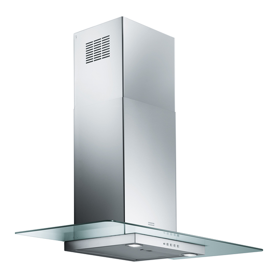
Franke FTC612 Mode D'emploi Et Installation
Masquer les pouces
Voir aussi pour FTC612:
- Mode d'emploi et installation (40 pages) ,
- Mode d'emploi et installation (40 pages)
Table des Matières
Publicité
Les langues disponibles
Les langues disponibles
Liens rapides
Instructions for use and installation
GB
Cooker Hood
Istruzioni per l'uso e l'installazione
IT
Cappa
Mode d'emploi et installation
FR
Hotte de Cuisine
Bedienungsanleitung und Einrichtung
DE
Dunstabzugshaube
Kullanım ve montaj talimatları
TR
Davlumbaz
See more at http://www.manualsworld.net
FGL 6015 XS
FGL 7015 XS
FGL 9015 XS
Publicité
Table des Matières

Manuels Connexes pour Franke FTC612


Sommaire des Matières pour Franke FTC612
- Page 1 Instructions for use and installation Cooker Hood Istruzioni per l’uso e l’installazione Cappa Mode d’emploi et installation Hotte de Cuisine Bedienungsanleitung und Einrichtung Dunstabzugshaube Kullanım ve montaj talimatları Davlumbaz FGL 6015 XS FGL 7015 XS FGL 9015 XS See more at http://www.manualsworld.net...
-
Page 2: Table Des Matières
INDEX RECOMMENDATIONS AND SUGGESTIONS ........................3 CHARACTERISTICS................................4 INSTALLATION ..................................5 USE......................................8 MAINTENANCE..................................9 INDICE CONSIGLI E SUGGERIMENTI ............................10 CARATTERISTICHE ................................11 INSTALLAZIONE..................................12 USO ......................................15 MANUTENZIONE .................................16 SOMMAIRE CONSEILS ET SUGGESTIONS ............................17 CARACTERISTIQUES .................................18 INSTALLATION ..................................19 UTILISATION..................................22 ENTRETIEN..................................23 INHALTSVERZEICHNIS EMPFEHLUNGEN UND HINWEISE............................24 CHARAKTERISTIKEN................................25 MONTAGE....................................26 BEDIENUNG..................................29 WARTUNG....................................30 IÇERIKLER TAVSIYELER VE ÖNERILER ..............................31... -
Page 3: Recommendations And Suggestions
RECOMMENDATIONS AND SUGGESTIONS The Instructions for Use apply to several versions of this appliance. Accord- ingly, you may find descriptions of individual features that do not apply to your specific appliance. INSTALLATION • The manufacturer will not be held liable for any damages resulting from in- correct or improper installation. -
Page 4: Dimensions
CHARACTERISTICS Dimensions 598 - 698 - 798 - 898 Min. Min. 500mm 650mm Components 14.1 Ref. Q.ty Product Components Hood Body, complete with: Controls, Light, Blower, 12a 7.2.1 Filters Telescopic Chimney comprising: Upper Section Lower Section Reducer Flange ø 150-120 mm 14.1 Air Outlet Connection Extension Air Outlet Connection... - Page 5 INSTALLATION Wall drilling and bracket fixing 7.2.1 Wall marking: • Draw a vertical line on the supporting wall up to the ceiling, or as high as practical, at the centre of the area in which the hood will be installed. •...
- Page 6 Mounting the hood body • Before attaching the hood body, tighten the two screws Vr lo- cated on the hood body mounting points. • Hook the hood body onto the screws 12a. • Fully tighten the support screws 12a. • Adjust the screws Vr to level the hood body. Connections DUCTED VERSION AIR EXHAUST SYSTEM When installing the ducted version, connect the hood to the...
-
Page 7: Electrical Connection
ELECTRICAL CONNECTION • Connect the hood to the mains through a two-pole switch hav- ing a contact gap of at least 3 mm. • Remove the grease filters (see paragraph Maintenance) being sure that the connector of the feeding cable is correctly inserted in the socket placed on the side of the fan. -
Page 8: Control Panel
Control panel BUTTON FUNCTIONS T1 Speed Turns the Motor on at Speed one. Turns the Motor off. T2 Speed Turns the Motor on at Speed two. T3 Speed Fixed When pressed briefly, turns the Motor on at Speed three. Light Turns the Lighting System on and off. - Page 9 MAINTENANCE Grease filters CLEANING METAL SELF- SUPPORTING GREASE FILTERS • The filters must be cleaned every 2 months of operation, or more frequently for particularly heavy usage, and can be washed in a dishwasher. • Remove the filters one at a time by pushing them towards the back of the group and pulling down at the same time.
-
Page 10: Consigli E Suggerimenti
CONSIGLI E SUGGERIMENTI Questo libretto di istruzioni per l'uso è previsto per più versioni dell' apparecchio. É possibile che siano descritti singoli particolari della dotazione, che non riguar- dano il Vostro apparecchio. INSTALLAZIONE • Il produttore declina qualsiasi responsabilità per danni dovuti ad installazione non corretta o non conforme alle regole dell’arte. - Page 11 CARATTERISTICHE Ingombro 598 - 698 - 798 - 898 Min. Min. 500mm 650mm Componenti 14.1 Rif. Q.tà Componenti di Prodotto Corpo Cappa completo di: Comandi, Luce, Gruppo 12a 7.2.1 Ventilatore, Filtri Camino Telescopico formato da: Camino Superiore Camino Inferiore Flangia di Riduzione ø 150-120 mm 14.1 Prolunga Raccordo Uscita Aria Raccordo Uscita Aria...
- Page 12 INSTALLAZIONE Foratura Parete e Fissaggio Staffe 7.2.1 Tracciare sulla Parete: • una linea Verticale fino al soffitto o al limite superiore, al centro della zona prevista per il montaggio della Cappa; • una linea Orizzontale a: 650 mm min. sopra il Piano di Cottura. •...
- Page 13 Montaggio Corpo Cappa • Prima di agganciare il Corpo Cappa, serrare le 2 Viti Vr situate sui punti di aggancio del Corpo Cappa. • Agganciare il Corpo Cappa alle Viti 12a. • Serrare definitivamente le Viti 12a di supporto. • Agire sulle Viti Vr per livellare il Corpo Cappa. Connessioni USCITA ARIA VERSIONE ASPIRANTE Per installazione in Versione Aspirante collegare la Cappa alla...
-
Page 14: Connessione Elettrica
CONNESSIONE ELETTRICA • Collegare la Cappa all’Alimentazione di Rete interponendo un Interruttore bipolare con apertura dei contatti di almeno 3 mm. • Rimuovere i Filtri antigrasso (vedi par. “Manutenzione”) e as- sicurarsi che il connettore del Cavo di alimentazione sia corret- tamente inserito nella presa dell’Aspiratore Montaggio Camino 7.2.1... -
Page 15: Quadro Comandi
Quadro comandi TASTO FUNZIONI T1 Velocità Acceso Accende il Motore alla Prima velocità. Spegne il Motore. T2 Velocità Acceso Accende il Motore alla Seconda velocità. T3 Velocità Fisso Premuto brevemente Accende il Motore alla Terza velocità. Luce Accende e spegne l’Impianto di Illuminazione. Attenzione: Il tasto T1 spegne il motore passando sempre per la prima velocità. - Page 16 MANUTENZIONE Filtri antigrasso PULIZIA FILTRI ANTIGRASSO METALLICI AUTOPORTANTI • Sono lavabili anche in lavastoviglie, e necessitano di essere lavati ogni 2 mesi circa di utilizzo o più frequentemente, per un uso particolarmente intenso. • Togliere i Filtri uno alla volta, spingendoli verso la parte poste- riore del gruppo e tirando contemporaneamente verso il basso.
-
Page 17: Conseils Et Suggestions
CONSEILS ET SUGGESTIONS La présente notice d'emploi vaut pour plusieurs versions de l'appareil. Elle peut conte- nir des descriptions d'accessoires ne figurant pas dans votre appareil. INSTALLATION • Le fabricant décline toute responsabilité en cas de dommage dû à une installation non correcte ou non conforme aux règles de l’art. -
Page 18: Caracteristiques
CARACTERISTIQUES Encombrement 598 - 698 - 798 - 898 Min. Min. 500mm 650mm Composants 14.1 Réf. Q.té Composants de Produit Corps Hotte équipé de:Commandes, Lumière, Groupe 12a 7.2.1 Ventilateur,Filtres Cheminée Télescopique formée de : Cheminée Supérieure Cheminée Inférieure Flasque de Réduction ø 150-120 mm 14.1 Rallonge Raccord Sortie Air Raccord Sortie Air... -
Page 19: Installation
INSTALLATION Perçage Paroi et Fixation Brides 7.2.1 Tracer sur la paroi: • une ligne verticale allant jusqu’au plafond ou à la limite supérieure, au centre de la zone prévue pour le montage de la hotte; • une ligne horizontale à 650 mm min. au-dessus du plan de cuisson. •... - Page 20 Montage Corps Hotte • Avant d’accrocher le corps hotte, serrer les deux vis Vr situées sur les points d’accrochage du corps hotte. • Accrocher le corps hotte aux vis 12a prévues à cet effet. • Serrer définitivement les vis 12a de support. •...
-
Page 21: Branchement Electrique
BRANCHEMENT ELECTRIQUE • Brancher la hotte sur le secteur en interposant un interrupteur bipolaire avec ouverture des contacts d’au moins 3 mm. • Enlever les filtres à graisse (voir § "Entretien") et s'assurer que le connecteur du câble d'alimentation soit bien branché dans la prise du diffuseur. -
Page 22: Utilisation
UTILISATION Tableau des commandes TOUCHE VOYANT FONCTIONS T1 Vitesse Allumé Démarre le moteur en première vitesse. Coupe le moteur. T2 Vitesse Allumé Démarre le moteur en deuxième vitesse. T3 Vitesse Fixe Appuyée brièvement, démarre le moteur en troisième vitesse. Lumière Branche et débranche l’éclairage. -
Page 23: Entretien
ENTRETIEN Filtres anti-graisse NETTOYAGE FILTRES ANTI-GRAISSE METALLIQUES AUTOPORTEURS • Lavables au lave-vaisselle, ils doivent être lavés environ tous les 2 mois d’emploi ou plus fréquemment en cas d’emploi par- ticulièrement intense. • Retirer les filtres l’un aprés l’autre, en les poussant vers la par- tie arrière du groupe et en tirant simultanément vers le bas. -
Page 24: Empfehlungen Und Hinweise
EMPFEHLUNGEN UND HINWEISE Diese Gebrauchsanleitung gilt für mehrere Geräte-Ausführungen. Es ist möglich, dass einzelne Ausstattungsmerkmale beschrieben sind, die nicht auf Ihr Gerät zutreffen. MONTAGE • Der Hersteller haftet nicht für Schäden, die auf eine fehlerhafte und unsachgemäße Mon- tage zurückzuführen sind. •... -
Page 25: Charakteristiken
CHARAKTERISTIKEN Platzbedarf 598 - 698 - 798 - 898 Min. Min. 500mm 650mm Komponenten 14.1 Pos. Produktkomponenten Haubenkörper mit Schaltern, Beleuchtung, Gebläse- 12a 7.2.1 gruppe, Filter Teleskopkamin bestehend aus: oberer Kaminteil unterer Kaminteil Reduzierflansch ø 150-120 mm 14.1 Verlängerung Luftaustritt-Anschlussstück Luftaustritt-Anschlussstück Pos. -
Page 26: Montage
MONTAGE Bohren der Befestigungslöcher und Fixieren der Befestigungsbügel 7.2.1 Achtung: Bitte beachten Sie bei der Montage das Gewicht der kompletten Haube. Die Tragfä- higkeit der Decke oder alternativ der Trägerplatte für diese Zugbelastung muss vor der Mon- tage geprüft und gegebenenfalls durch die Anbringung von geeigneten Befestigungs- oder Stabilisierungselementen hergestellt werden. - Page 27 Montage des Haubenkörpers • Bevor der Haubenkörper eingehakt wird, die 2 Schrauben Vr bei den Haubenkörper-Anhakpunkten festziehen. • Den Haubenkörper bei den Schrauben 12a einhängen. • Die Halteschrauben 12a definitiv festziehen. • Den Haubenkörper mit Hilfe der Schrauben Vr ausrichten. Anschluss der Abluftversion Bei Abluftbetrieb kann die Haube vom Installateur wahlweise mittels Rohr oder Schlauch (ø...
- Page 28 Elektroanschluss Vor der Installation die Netzspannung durch herausdrehen der Sicherung oder ausschalten des Hauptschalters stromlos ma- chen. • Bei Anschluss der Haube an das Stromnetz muss ein zweipoliger Schalter einem Öffnungsweg mindestens 3 mm zwischengeschaltet werden. • Entfernen Sie die Fettfilter (s. Abschnitt „Wartung“) und versichern Sie sich, daß...
-
Page 29: Bedienung
BEDIENUNG Schalttafel TASTE FUNKTIONEN T1 Betriebsgeschwindigkeit Eingeschaltet Schaltet Motor ersten Betriebsgeschwindigkeit ein. Stellt den Motor ab. T2 Betriebsgeschwindigkeit Eingeschaltet Schaltet Motor zweiten Betriebsgeschwindigkeit ein. T3 Betriebsgeschwindigkeit Bleibend Schaltet Motor dritten Betriebsgeschwindigkeit ein. Licht Schaltet die Beleuchtung ein und aus. Achtung: Mit der Taste T1 wird von der ersten Betriebsgeschwindigkeit aus der Motor abgestellt. -
Page 30: Wartung
WARTUNG Fettfilter SELBSTTRAGENDER METALLFETTFILTER REINIGUNG • Sie müssen nach 2-monatigem Betrieb bzw. bei starkem Ein- satz auch häufiger gereinigt werden, was im Geschirrspüler möglich ist. • Die Filter nacheinander aushaken, indem sie auf die Rückseite der Gruppe geschoben und gleichzeitig nach unten gezogen werden. -
Page 31: Tavsiyeler Ve Öneriler
TAVSIYELER VE ÖNERILER Bu kullanma talimatι birden fazla cihaz modeli için geçerlidir. Cihazιnιza uymayan bazι donanιm özellikleri tarif edilmiş olabilir. MONTAJ • Yalnιş veya eksik montajdan doğan herhangi bir zararιn sorumluluğu üreticiye ait değildir. • Davlumbaz ile pişirici cihazιn ocak kιsmι arasιndaki minimum güvenlik mesafesi 650 mm.dir (bazı... -
Page 32: Özellikler
ÖZELLIKLER Boyutlar 598 - 698 - 798 - 898 Min. Min. 500mm 650mm Parçalar 14.1 Ref. Adet Ürünün parçaları Şunlardan oluşan davlumbaz gövdesi: Kumandalar, 12a 7.2.1 Lamba, Fan grubu, Filtreler Şunlardan oluşan teleskopik baca: Üst baca Alt baca Redüksiyon Flanşı ø 150-120 mm 14.1 Hava Çıkışı... -
Page 33: Montaj
MONTAJ Duvarın Delinmesi ve Braketlerin Sabitlenmesi 7.2.1 Duvara şunları çiziniz: • Tavana yada üst sınıra kadar uzunan Dikey bir çizgi: Davlumbazın monte edileceği yerin tam merkezinden geçmelidir; • Tezgâh (setüstü ocak) yüzeyinden 650 mm mesafeden geçen bir Yatay çizgi. • Gösterildiği gibi Braketi 7.2.1 tavandan 1-2 mesafeye dayayınız ve bunun merkezini (çen- tik) Dikey referans çizgisine hizalayınız. - Page 34 Davlumbaz Gövdesi Montajı • Davlumbaz Gövdesini kancalara takmadadan önce gövde üze- rindeki kancalama noktalarında bulunan 2 adet vidayı Vr sıkı- nız. • Davlumbaz Gövdesini vidalara 12a takınız. • Destek vidalarını 12a nihai olarak sıkınız. • Vr vidalarına müdahale ederek Davlumbaz Gövdesi seviyesini hizalayınız.
-
Page 35: Elektri̇k Bağlantisi
ELEKTRİK BAĞLANTISI • Davlumbazı şebeke cereyanına bağlarken aray temas aralığı en az 3 mm olan çift kutuplu bir elektrik anahtarı koyunuz. • Yağ tutucu filtreleri çıkarınız (bakınız "Bakım" paragrafı) ve besleme kablosu soketinin aspiratör prizine iyice takılmış ol- duğundan emin olunuz. Bacanın montajı... -
Page 36: Kullanim
KULLANIM Kumanda Tablosu TUŞ FONKSİYON T1 Hız Açık Birinci hızda motoru çalıştırır. Motoru durduruyor. İkinci hızda motoru çalıştırır. T2 Hız Açık T3 Hız Sabit Hafifçe basılınca, üçüncü hızda motoru çalıştırır. Işık Işık tesisatını açıp kapatır. Dikkat: T1 tuşu daima ilk hızdan geçerek motoru durdurur. See more at http://www.manualsworld.net... -
Page 37: Bakim
BAKIM Yağ tutucu filtreler METALİK YAĞ TUTUCU FİLTRELERİN TEMİZLENMESİ • Bu filtreler bulaşık makinasında da yıkanabilir ve normal kul- lanıldıklarında iki ayda bir, yoğun kullanım halinde ise daha sıkça yıkanmalarıı gereklidir. • Filtrleri, grubun arka tarafından ittirerek ve aynı anda aşağı doğru çekerek tek tek çıkarınız. - Page 38 See more at http://www.manualsworld.net...
- Page 39 See more at http://www.manualsworld.net...
- Page 40 Franke S.p.a. Via Pignolini,2 37019 Peschiera del Garda (VR) www.franke.it 436004820_ver1 See more at http://www.manualsworld.net...