Partner K650 ACTIVE II Manuel D'utilisation
Table des Matières
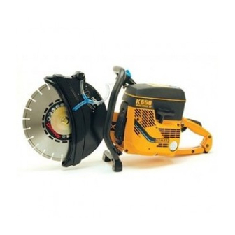
K650 ACTIVE II
K700 ACTIVE II
K850 MARK II
K1200 MARK II
Operator's manual
E E E E E
Read these instructions carefully and make sure
you understand them before using the machine.
D D D D D
Bedienungs-
anweisung
Lesen Sie die Bedienungsanweisung sorgfältig
durch und machen Sie sich mit dem Inhalt vertraut,
bevor Sie die Machine benutzen.
F F F F F
Manuel d'utilisation
Lire attentivement et bien assimiler le manuel
d'utilisation avant de se servir de la machine.
Manual de
e e e e e
instrucciones
Antes de utilizar la máquina, lea bien el manual de
instrucciones hasta comprender su contenido.
Table des Matières

Manuels Connexes pour Partner K650 ACTIVE II


Sommaire des Matières pour Partner K650 ACTIVE II
- Page 1 K650 ACTIVE II K700 ACTIVE II K850 MARK II K1200 MARK II Operator’s manual E E E E E Read these instructions carefully and make sure you understand them before using the machine. D D D D D Bedienungs- anweisung Lesen Sie die Bedienungsanweisung sorgfältig...
- Page 2 E E E E E Contents Controls ................ 19 Foreword ................ 1 Starting the engine ............20 Symbols in the operator´s manual ........ 2 Starter assembly ............. 21-23 Symbols on the power cutter ........3 Air filter K 650/K 700 ..........24-25 Operator Safety Precautions ........
-
Page 3: Avant-Propos
E E E E E Foreword The power cutter is a machine with a high cutting capacity and it is fitted with safety features to make the work carried out as safe as possible. If the safety features are out of WARNING! operation or if the machine is used carelessly or wrongly, the Use only cutting wheels approved for use with high... - Page 4 E E E E E Symbols in the operator´s manual WARNING! This power cutter can be hazardous. Study the operator´s manual carefully and Careless or incorrect use of this machine can make sure that you understand the contents result in serious, even fatal, injuries. before using the power cutter.
-
Page 5: Symboles Sur La Découpeuse
E E E E E Symbols on the power cutter Warning WARNING! This power cutter can be hazardous. Cutting creates a lots of dust which can cause Careless or incorrect use of this machine can inhalation damages. Use appropriate dust result in serious, even fatal, injuries. -
Page 6: Consignes De Sécurité Pour L'utilisateur
E E E E E Operator Safety Precautions starting or cutting. Keep bystanders and animals out of the work area. 1. Never operate the machine when you are tired, angry, 5. Never start cutting until you have a clear work area and emotionally disturbed, or under the influence of alcohol, secure footing. - Page 7 E E E E E 11. Never operate a cutting machine that is damaged, im- 16. All service other than items listed in the maintenance properly adjusted, or not completely and securely ass- instructions on page 35 should be performed by com- embled.
- Page 8 K650 Active II/ K700 Active II K850 Mark II / K1200 Mark II...
- Page 9 E E E E E Pos. Description Cutter disc Cover for air filter Guard Air filter Knob for guard adjustment Spark plug (under cover) Stop switch Decompression valve (K650/K700) Choke Drive belt Throttle trigger lockout Cutting arm Throttle control Belt tensioner Starter throttle control Drive wheel, clutch (behind clutch cover) Starter handle...
- Page 10 E E E E E Assembling the cutter arm K1200/K850 Remove the two drive belt protective casings (1). Fit the arm on the motor and tighten the nuts (2) by hand. Remove the nuts (2) for the cutter arm. D D D D D Einbau des Trennarms K1200/K850 Die beiden Riemenschutzkappen ausbauen (1).
- Page 11 E E E E E Fit the drive belt and tension it by turning the eccentric (3) A new belt must be retightened after approx. 30 minutes to its bottom position (clockwise) using socket wrench of operation and then check the tension daily by 501 6917-02.
- Page 12 E E E E E Reversing the cutting arm K1200/K850 It is possible to reverse the cutting arm 180 so that the The cutter arm is loosened in the same way as when cutter wheel is positioned on the opposite side of the changing the drive belt, see page 16.
- Page 13 E E E E E Reversing the cutting arm K650/K700 It is possible to reverse the cutting arm 180 so that the Turn the arm 180 and then refit parts and screw into cutter wheel is positioned on the opposite side of the position as earlier.
-
Page 14: Cutting Wheel
E E E E E Cutting wheel The wheel is placed between the flange washer A and The cutting wheel is tightened with the fixed wrench B. Check the arbor bushing so that it corresponds with 501 69 17-02, that is delivered with the power cutter. Use the size of the hole in the wheel. - Page 15 E E E E E WARNING The spindle is secured by means of pin 503 24 06-02, Never operate without the wheel guard. which is pushed in as far as possible. The wheel is The guard should be adjusted so that its rear section is tightened clockwise.
- Page 16 E E E E E Drive belt K650/K700 The belt is completely enclosed and well protected from Adjust the tensioning screw so that the nut is positioned dust and dirt as well as from mechanical damage during at the arrow marked on the cover. Shake the arm to cutting work.
- Page 17 E E E E E Drive belt K1200/K850 To replace the belt loosen the two nuts and then the tensioning screw until the tension is released. Remove To stretch the belt, loosen the nuts retaining the cutting the nuts and the belt cover. The cutting arm can now be arm.
- Page 18 E E E E E To replace the belt, remove both the casings on the The cutting arm can then be pressed back and the belt cutting arm. Loosen the nuts holding the cutting arm. removed. Turn the eccentric counterclockwise by using the spark The belt tensioner consist of a powerful spring tensioned plug wrench so that the tension on the spring is released.
- Page 19 Utilice en primera instancia el aceite para motores de dos tiempos de • Si se le ha derramado combustible encima o en sus Partner. Merzcla: 2%. En segunda instancia utilice otro aceite para motores ropas, debe cambiarlas. de dos tiempos de renombre. Mezcla: 4%. No utilice nunca aceite para •...
-
Page 20: Fuel Filter
E E E E E Fuel filter Wipe the area around the fuel cap clean before the filler cap is removed. Dirt in the fuel tank will clog up the fuel filter (A) and cause running interruptions. The filter cartridge cannot be cleaned but must be replaced if it becomes blocked. - Page 21 K1200/K850 K650/K700 E E E E E Controls A Stop switch. When the button is pressed backwards, control and the throttle is blocked in half throttle position. STOP the engine stops. The button remains in this position and The catch is released when the throttle control is pressed must be returned to its initial position before the engine in all the way.
-
Page 22: Starting The Engine
E E E E E Starting the engine Make sure the stop switch (A) is in running position WARNING! (pushed forward). Pull the choke control (B) if the engine The cutting wheel will start to rotate when the saw starts. is cold. -
Page 23: Pour Remplacer Le Cordon De Démarrage
E E E E E Replacing the starter cord 1. Remove the air filter and cylinder cover. 3. Pull out the starter cord a little and prevent the pulley 2. Remove the four screws and lift away the starter. from rotating backwards. 4. - Page 24 E E E E E 5. Remove the locking spring or screw and lift up the 9. Wind three turns of the cord on the pulley clockwise starter pulley. and place it in the housing. 6. Pull the new starter cord through the hole in the pulley 10.
-
Page 25: Replacing The Starter Spring
E E E E E Replacing the starter spring WARNING! 1. Follow the same procedure as described above When the recoil spring is assembled in the starter housing, for replacement of the starter cord. 2. Then remove the screw holding the spring it is in tensioned position and can when treated carelessly, cassette to the starter housing. - Page 26 E E E E E Air filter K650/K700 The filter system consists of a centrifugal cleaning nozzle The main filter (2) is removed by means of loosening the (1), main filter (2) and protective filter (3). two screws which hold the filter cover. The main filter is an oil saturated foam filter and the The main filter should be replaced after approx.
- Page 27 E E E E E Air filter K650/K700 When dismanting the cylinder cover it is important to check The protective filter (3), which is a paper filter, is mounted that the seal D is in good condition and that it is correctly in the cylinder cover under the filter base.
- Page 28 E E E E E Air filter K1200/K850 The air filter systems consists of a pre-filter (1), a main The pre-filter must be pulled off and shaken clean in filter (2) and a spill filter (3). connection with every tanking operation. The pre-filter should be thoroughly washed or replaced after 30 hours The pre-filter can be changed without using any tools and of operation in steel material or after 20 hours of opera-...
- Page 29 E E E E E The main filter is a paper unit of a special quality grade which When replacing the spillfilter it is important that the seal must not be washed or blown clean. The filter may only shaken between the intake pipe and the cylinder cover is clean.
-
Page 30: Carburateur
E E E E E Carburettor When the cutter is tested at the factory, the carburettor is NOTE! adjusted to a basic setting: Small variations from the basic setting influence the rpm of the saw substantially. High speed needle H: 7/8 turn open Low speed needle L: 1 1/8 turn open Basic setting of carburettor Local climate and differences in altitude may require an... -
Page 31: Réglage Du Régime De Ralenti
E E E E E Low speed needle L Idle speed setting Apply full throttle a couple of times and check that the saw is accelerating without hesitation. If an adjustment is necessary, adjust with the screw marked T on If an adjustment is necessary, try to reach the maximum the cover. - Page 32 E E E E E 3. Repeat step 1 and 2 until you notice a slight hesita- High speed needle H tion. 4. From the position that creates the hesitation under The engine is equipped with a carburettor which has a acceleration from idle, back out the H-jet (counter- built-in governor.
-
Page 33: Réglage Final Du Régime De Ralenti T
E E E E E Final setting of the idling speed T A correctly adjusted idle speed setting (approx. 2.500 Adjust the idling speed with the screw marked T. rpm) occurs when the engine runs smoothly in every Corrections to the setting of the idling speed should be position. -
Page 34: Spark Plug
E E E E E Spark plug If the engine is low on power, difficult to start or runs IMPORTANT! poorly at idling speed, always check the spark plug first. Always use the recommended spark plug type, Cham- If the spark plug is dirty, clean it and check the electrode pion RCJ-7Y or NGK BPMR 7A. -
Page 35: Working Technique
E E E E E Working technique When cutting steel and other metals, always try to When cutting stone, concrete and similar material the maintain high cutting pressure and high wheel speed. Try wheel should be moved forwards and backwards in the to get a smallest possible contact point by moving the cut to obtain good conduction of heat away from the wheel back and forth in the cut. -
Page 36: Maintenance Scheme
E E E E E Maintenance scheme The following is a summary of various measures mentioned in the book and which is essential for the correct servicing of the power cutter. The time intervals mentioned should be applied if the power cutter is used for at least 4 hours every day. If the machine is used for a shorter time each day, the shortest intervals can be extended without any ill effects. -
Page 37: Schema D'entretien
F F F F F Schema d’entretien Ci-dessous un tableau résumant les interventions mentionnées dans le manuel et qui sont essentielles au bon fonctionnement de la découpeuse. La fréquence indiquée doit être suivie si l’outil est utilisé au moins 4 heures par jour. Si l’utilisation est moins grande chaque jour, les intervalles peuvent être augmentés sans inconvénient. - Page 38 Tools Werkzeuge Outils Herramientos K650 Active II K700 Active II 501 69 17-02 K850 Mark II K1200 Mark II 505 38 13-07 503 24 06-02 501 69 17-02 501 60 02-02...
-
Page 39: Technical Data
We, Partner Industrial Products, S-433 81 Partille, Sweden, tel. +46-31-949000, declare under sole responsibility that the power cutters Partner K650 Active II/K700 Active II/K850 Mark II/K1200 Mark II from the serial numbers of 1999 and onwards (the year is clearly stated in plain text on the type plate with subsequent serial number), is in conformity with the following standards or other normative documents following the provisions in the COUNCIL’S... -
Page 40: Technische Daten
Wir, Partner Industrial Products, S-433 81 Partille, Schweden, Tel. +46-31-949000, erklären hiermit unsere alleinige Haftung dafür, daß die Trennschleifer Partner K650 Active II/K700 Active II/K850 Mark II/K1200 Mark II, auf die sich diese Erklärung bezieht, von den Seriennummern des Baujahrs 1999 an (die Jahreszahl wird im Klartext... -
Page 41: Données Techniques
Nous, Partner Industrial Products, S-433 81 Partille, Suède, tel. +46-31-949000, déclarons, sous notre seule responsabilité, que le produit auquel se rattache la présente déclaration : les découpeuses thermique Partner K650 Active II/K700 Active II/K850 Mark II/K1200 Mark II à partir des numéros de série de l'année de fabrication 1999 et ultérieurement (l'année est indiquée en clair sur la plaque d'identification et suivie d'un numéro de série) est conforme... -
Page 42: Datos Técnicos
Partner Industrial Products, S-433 81 Partille, Suecia, tel. +46-31-949000, certifica mediante este documento que las cortadoras Partner K650 Active II/K700 Active II/K850 Mark II/K1200 Mark II, desde los números de serie del año 1999 en adelante (el año se indica claramente en la placa del motor, seguido del número de serie), cumple con lo que establecen las DIRECTIVAS DEL CONSEJO: - del 14 de junio de 1989 “sobre máquinas”... - Page 43 E E E E E Safety rule checklist Operation Operator Before start • Is fully instructed in use of the power cutter. • Controls work smoothly and correctly. • Has read and fully understands the safety manual and this • Tank filled min.
-
Page 44: Pflege Der Trennscheiben
D D D D D Sicherheitscheckliste Betrieb Bediener Vor dem Anlassen • Voll in der Bedienung des Trennschleifer ausgebildet. • Bedienungsvorrichtungen funktionieren reibungslos und • Hat das Sicherheitshandbuch und diese Bedienungsanweisung richtig. gelesen und voll verstanden. • Tank wurde mindestens 3 Meter von Schneidstelle entfernt •... -
Page 45: Liste De Contrôle, Prescriptions De Sécurité
F F F F F Liste de contrôle, prescriptions de Utilisation sécurité Avant la mise en route L’utilisateur devra • Les commandes fonctionnent sans remarque. • avoir appris comment utiliser la découpeuse • Le réservoir de carburant est rempli au moins à 3 mètres du •... - Page 46 e e e e e Funcionamiento Lista de chequeo de seguridad Antes del arranque Usuario • Controlar que los mandos se accionan con facilidad y • Ha sido instruido en el manejo de la máquina. • Ha léido y comprendido el manual de seguridad y el manual de correctamente.
- Page 47 108 87 68-77 ´*xlw¶7_¨ 1999W04...