Table des Matières
Publicité
Les langues disponibles
Les langues disponibles
Liens rapides
LCIE 07 ATEX 6078 X
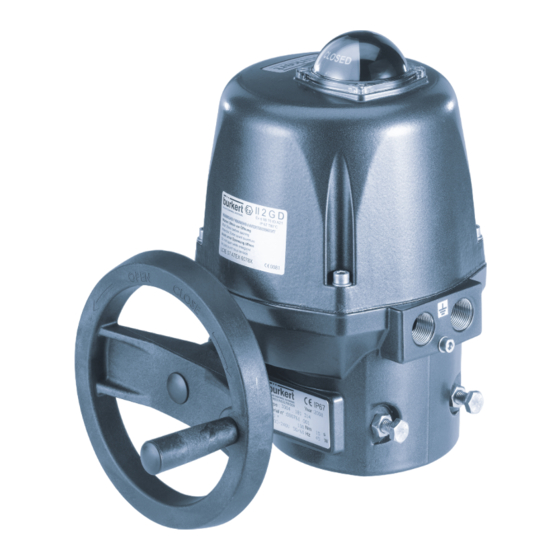
Electric rotary actuator type 3004
Elektrischer Drehantrieb Typ 3004
Actionneur électrique type 3004
Device with II 2 GD Ex d IIB T6 approval
Geräte mit II 2 GD Ex d IIB T6 Zulassung
Appareils certifiés II 2 GD Ex d IIB T6
Operating Instructions
Bedienungsanleitung
Instructions de Service
Publicité
Chapitres
Table des Matières
Dépannage

Manuels Connexes pour Burkert LCIE 07 ATEX 6078 X


Sommaire des Matières pour Burkert LCIE 07 ATEX 6078 X
- Page 1 LCIE 07 ATEX 6078 X Electric rotary actuator type 3004 Elektrischer Drehantrieb Typ 3004 Actionneur électrique type 3004 Device with II 2 GD Ex d IIB T6 approval Geräte mit II 2 GD Ex d IIB T6 Zulassung Appareils certifiés II 2 GD Ex d IIB T6...
- Page 40 Type 3004 English...
- Page 78 Typ 3004 deutsch...
- Page 79 Type 3004 Actionneur électrique type 3004 protégé contre les explosions able des matIeres MANUEL D’UTILISATION ................................81 1.1. Symbole ....................................81 UTILISATION CONFORME ................................82 2.1. Conditions d’utilisation ..............................82 CONSIGNES DE SÉCURITÉ FONDAMENTALES ......................83 INDICATIONS GÉNÉRALES ................................84 4.1. Adresse ....................................84 4.2. Garantie légale ..................................84 4.3. Aucun remplacement des appareils déjà livrés ....................84 4.4. Informations sur Internet ..............................84 DESCRIPTION DU SYSTÈME ..............................85 5.1. Utilisation prévue .
- Page 80 Type 3004 INSTALLATION ....................................99 8.1. Consignes de sécurité ..............................99 8.2. Installation électrique ...............................99 8.3. Carte de positionnement ............................. 103 OPTION: ACTIONNEUR ÉLECTRIQUE AVEC VARIANTE À COURANT DE SECOURS......107 9.1. Description ..................................107 9.2. Caractéristiques techniques ............................107 9.3. Raccordement électrique du bloc de sécurité ....................108 9.4. Montage du bloc de sécurité dans l’actionneur électrique ............... 109 MISE EN SERVICE ..................................110 10. 10.1. Consignes de sécurité ..............................110 10.2. Procédure à suivre ................................110 11. UTILISATION ET FONCTIONNEMENT .
-
Page 81: Manuel D'utilisation
Type 3004 Manuel d’utilisation MANUEL D’UTILISATION Les instructions de service décrivent le cycle de vie complet de l'appareil. Conservez ces instructions de sorte qu'elles soient accessibles à tout utilisateur et à disposition de tout nouveau propriétaire. AVERTISSEMENT ! Les instructions de service contiennent des informations importantes sur la sécurité ! Le non-respect de ces consignes peut entraîner des situations dangereuses. •... -
Page 82: Utilisation Conforme
Type 3004 Utilisation conforme UTILISATION CONFORME AVERTISSEMENT ! L'utilisation non conforme de l’actionneur électrique peut présenter des dangers pour les personnes, les installations proches et l'environnement. • L‘actionneur électrique peut être utilisé, par ex. pour actionner des vannes, en particulier des vannes à bois- seau sphérique ou des vannes papillon. • L'utilisation doit se faire dans le respect des données admissibles spécifiées dans les documents contrac- tuels et les instructions de service ainsi que des conditions d'exploitation et d'utilisation décrites au chapitre «... -
Page 83: Consignes De Sécurité Fondamentales
Type 3004 Consignes de sécurité fondamentales CONSIGNES DE SÉCURITÉ FONDAMENTALES Ces consignes de sécurité ne tiennent pas compte : • Des hasards et des événements pouvant survenir lors du montage, de l'exploitation et de l'entretien des appareils. • Des prescriptions de sécurité locales que l'exploitant est tenu de faire respecter par le personnel chargé du montage. DANGER ! Danger présenté par la tension électrique ! Il y a risque important de blessures lors d'interventions sur l'appareil. -
Page 84: Indications Générales
Type 3004 Indications générales INDICATIONS GÉNÉRALES 4.1. Adresse Allemagne Bürkert Fluid Control System Sales Center Chr.-Bürkert-Str. 13-17 D-74653 Ingelfingen Tél. : +49 (0)7940 - 10 91 111 Fax : +49 (0)7940 - 10 91 448 E-mail : info@de.buerkert.com International Les adresses se trouvent aux dernières pages des instructions de service imprimées. Egalement sur internet sous : www.buerkert.com 4.2. -
Page 85: Description Du Système
Type 3004 Description du système DESCRIPTION DU SYSTÈME 5.1. Utilisation prévue L’actionneur électrique du type 3004 (appelé ci-après actionneur) a été développé pour commander les vannes à boisseau sphérique ou les vannes papillon quart de tour. L'actionneur électrique est également disponible avec un angle de rotation de 180°... -
Page 86: Vues Éclatées
Type 3004 Description du système 5.3. Vues éclatées Moteur 25 – 75 Nm Moteur 25 – 75 Nm avec carte de positionnement Figure 1 : Vue éclatée du moteur 25 – 75 Nm N° Désignation N° Désignation Indicateur de position Carter Capot Plaque signalétique Vis en acier inoxydable Contacts de recopie + fin de course Moteur Cames 5.a*... - Page 87 Type 3004 Description du système Moteur 100 - 300 Nm Motor 100 - 300 Nm avec carte de positionnement Figure 2 : Vue éclatée du moteur 100 – 300 Nm N° Désignation N° Désignation Indicateur de position Boîtier Capot Plaque signalétique Vis en acier inoxydable Contacts de recopie + fin de course Moteur Cames 5.a*...
-
Page 88: Options
Type 3004 Description du système 5.4. Options • Actionneur électrique trois positions (180°) • Angle de rotation 180° ou 270° • Actionneur électrique avec potentiomètre de recopie: - Potentiomètre avec valeurs de résistance 100 W, 1 KW, 5 KW ou 10 KW - Carte de positionnement signal : 0 –... -
Page 89: Caractéristiques Techniques
Type 3004 Caractéristiques techniques CARACTÉRISTIQUES TECHNIQUES 6.1. Conformité L’actionneur électrique du type 3004 est conforme aux directives CE en accord avec la déclaration de conformité. 6.2. Normes La conformité avec les directives CE est satisfaite avec les normes suivantes : •... -
Page 90: Informations Sur La Plaque Signalétique
Type 3004 Caractéristiques techniques 6.5.1. Informations sur la plaque signalétique Exemple Conformité CE Type de protection FLUID CONTROL SYSTEMS Year : 2007 Date de fabrication G 74653 INGELFINGEN Type : 3004 182 384 Désignation de type Couple de manœuvre Serial n° : 086417 001 N°... -
Page 91: Caractéristiques Techniques Générales
Type 3004 Caractéristiques techniques 6.6. Caractéristiques techniques générales 6.6.1. Caractéristiques mécaniques Dimensions : Voir chapitre « 6.6.2. Dimensions » Poids : 25 – 75 Nm ; 4 kg 100 – 300 Nm ; 6,5 kg Matériau du carter : Capot et carter en aluminium, revêtus Epoxy Axes et vis en acier inoxydable Engrenage en acier zingué... - Page 92 Type 3004 Caractéristiques techniques 6.6.2. Dimensions Moteur 25 – 75 Nm Figure 5 : Dimensions type 3004 avec couple 25 – 75 Nm français...
- Page 93 Type 3004 Caractéristiques techniques Moteur 100 – 300 Nm Figure 6 : Dimensions type 3004 avec couple 100 – 300 Nm français...
-
Page 94: Caractéristiques Électriques
Type 3004 Caractéristiques techniques 6.6.3. Caractéristiques électriques Raccordements : 2 raccords filetés ISO 20 Contacts de fin de course : 2 contacts de fin de course pour le moteur 2 contacts de fin de course sans potentiel (pour signal de recopie) Puissance : maxi 250 V AC / 5 A Caractéristiques électriques pour la version standard sans signal analogique et la version de positionnement... -
Page 95: Montage
Type 3004 Montage MONTAGE 7.1. Consignes de sécurité DANGER ! Danger présenté par la tension électrique ! Il y a risque important de blessures lors d'interventions sur l'appareil. • Coupez toujours la tension et empêchez toute remise sous tension avant de retirer le capot, de séparer l'engrenage ou d'utiliser le levier. - Page 96 Type 3004 Montage Taille d‘actionneur électrique [Nm] Taille de l’entraineur [mm] 100 / 150 / 300 22 / 17 Des douilles de réduction à commander séparément permettent d'adapter le montage de l’actionneur sur tout type de vanne à boisseau sphériques ou vannes papillon. Vous trouverez les références et un aperçu des douilles de réduction disponibles au chapitre «...
-
Page 97: Réglage Des Contacts De Recopie
Type 3004 Montage 7.2.3. Réglage des contacts de recopie Les contacts de fin de course sont réglés en usine sur 0 – 90°. Démonter l'indicateur de position et le capot Figure 8 : Démontage du hublot Figure 9 : Démontage de l'indi- Figure 10 : Démontage du capot plastique cateur de position Procédure à suivre :... - Page 98 Type 3004 Montage L'actionneur électrique est fourni départ usine avec les réglages suivants : • Le contact de fin de course FERME (FCF) est actionné par la came (position fermée). • Le contact de fin de course OUVERT (FCO) est réglé sur un angle de rotation de 90°. Recopie Alimentation en tension et commande...
-
Page 99: Installation
Type 3004 Installation INSTALLATION 8.1. Consignes de sécurité AVERTISSEMENT ! Danger dû à un montage non conforme ! Un montage non conforme peut entraîner des blessures et endommager l'appareil et son environnement. • Ces travaux doivent être effectués uniquement par des techniciens qualifiés et habilités disposant de l'outillage approprié... -
Page 100: Version Standard
Type 3004 Installation 8.2.2. 100-240 V AC (100-350 V DC) ou 15-30 V AC (12-48 V DC) Version standard La tension d'alimentation de l'actionneur électrique est de 15-30 V AC (12-48 V DC) ou 100-240 V AC (100-350 V DC). Respectez absolument les indications figurant sur la plaque signalétique ! Figure 14 : Alimentation en courant: carte 15-30 V... - Page 101 Type 3004 Installation Figure 16 : Mode trois points modulants Figure 17 : Mode ouverture/fermeture / La variante à courant de secours Lorsque la tension est appliquée simultanément aux bornes 2 et 3, la borne 2 est prioritaire et l’actionneur se déplace sur la position OUVERT.
-
Page 102: Version Avec Entrée De Signal Analogique
Type 3004 Installation Les contacts de fin de course sont actionnés par deux cames n° 13 (voir « Figure 1 », page 86 et « Figure 2 », page 87). • La came blanche sert à détecter l'ouverture (FC1). • La came noire sert à détecter la fermeture (FC2). Procédure à suivre : →... -
Page 103: Carte De Positionnement
Type 3004 Installation Raccorder les contacts de recopie Les contacts de recopie conviennent à une tension maximale de 250 V AC/DC – 5 A. L’actionneur électrique est doté de deux contacts de recopie réglés en usine en position ouverte. Ils peuvent être utilisés pour la recopie de l’actionneur électrique. Les contacts du contact de fin de course sont actionnés par deux cames n°... -
Page 104: Position Des Cavaliers
Type 3004 Installation 8.3.1. Position des cavaliers (activé) (désactivé) Figure 21 : Cavaliers K1 / K2 Figure 22 : Cavalier K3 OFF Figure 23 : Cavalier K3 ON Cavalier K1 Cavalier K2 Emetteur de Cavalier Recopie commande 0 à 10 V 0 à 10 V 0 à 10 V 0 à 20 mA 0 à 10 V 4 à 20 mA 0 à 20 mA 0 à 10 V 0 à 20 mA... -
Page 105: Étapes De Paramétrage
Type 3004 Installation 8.3.2. Étapes de paramétrage Déterminer le sens de rotation de la vanne d'arrêt Sens de rotation normal (préréglé) → Appuyer sur le bouton-poussoir <OPEN> et activer la carte (maintenir le bouton-poussoir enfoncé). La LED VERTE s'allume. → Relâcher le bouton-poussoir <OPEN> et mettre la carte hors tension. Sens de rotation inverse → Appuyer sur le bouton-poussoir <CLOSE>... -
Page 106: Mode Normal
Type 3004 Installation Mode apprentissage Déterminer les positions finales → Appuyer sur les boutons-poussoirs <OPEN> et <CLOSE> et activer la carte (maintenir les boutons-poussoirs enfoncés). Les LED ROUGE et VERTE s'allument. → Relâcher les boutons-poussoirs <OPEN> et <CLOSE>. Les deux LED s'éteignent. Le mode apprentissage est sélectionné. →... -
Page 107: Option: Actionneur Électrique Avec Variante À Courant De Secours
Type 3004 Option: Actionneur électrique avec variante à courant de secours OPTION: ACTIONNEUR ÉLECTRIQUE AVEC VARIANTE À COURANT DE SECOURS 9.1. Description La variante à courant de secours est composée d‘un bloc de sécurité intégré pour le rappel de secours. Bloc batterie 24 V Raccordement Vis ST2,2 x 6,5... -
Page 108: Raccordement Électrique Du Bloc De Sécurité
Type 3004 Option: Actionneur électrique avec variante à courant de secours 9.3. Raccordement électrique du bloc de sécurité 9.3.1. Schéma électrique Bloc de batterie de 24 V DC Couleur du fil Commande et rouge carte d’alimentation en courant Couleur du fil noir Recopie de l’état de charge de la batterie Le contact est fermé... -
Page 109: Montage Du Bloc De Sécurité Dans L'actionneur Électrique
Type 3004 Option: Actionneur électrique avec variante à courant de secours Description d’état des LED Etat Description Verte allumée Alimentation par le réseau clignote Alimentation par batterie Rouge allumée La batterie est chargée clignote La batterie se charge 9.4. Montage du bloc de sécurité dans l’actionneur électrique 4 vis de fixation ST2,2 x 6,5 Figure 27 :... -
Page 110: Mise En Service
Type 3004 Mise en service MISE EN SERVICE 10.1. Consignes de sécurité AVERTISSEMENT ! Danger dû à une utilisation non conforme ! Une utilisation non conforme peut entraîner des blessures et endommager l'appareil et son environnement. • Avant la mise en service, il faut s'assurer que le contenu des instructions de service est connu et parfaitement compris par les opérateurs. -
Page 111: Utilisation Et Fonctionnement
Type 3004 Utilisation et fonctionnement UTILISATION ET FONCTIONNEMENT 11.1. Consignes de sécurité AVERTISSEMENT ! Danger présenté par la tension électrique ! Il y a risque important de blessures lors d'interventions sur l'appareil. • Coupez l’alimentation avant d'utiliser manuellement l'actionneur électrique. • Veuillez respecter les réglementations en vigueur pour les appareils électriques en matière de prévention des accidents ainsi qu'en matière de sécurité... -
Page 112: Maintenance, Dépannage
Type 3004 Maintenance, dépannage MAINTENANCE, DÉPANNAGE 12.1. Consignes de sécurité DANGER ! Danger présenté par la tension électrique ! Il y a risque important de blessures lors d'interventions sur l'appareil. • Avant d’effectuer des travaux, coupez toujours l’alimentation et empêchez toute remise sous tension par inadvertance ! •... -
Page 113: Accessoires
Type 3004 Accessoires Panne Remède → La vanne ne s'ouvre ou ne se ferme pas Vérifiez l'alimentation en courant. complètement → Vérifiez les raccordements selon le schéma électrique fourni. → Vérifiez les contacts de fin de course. → Vérifiez s'il y a surcharge sur la vanne due à un couple de manœuvre trop élevé... -
Page 114: Emballage, Transport
Type 3004 Emballage, transport EMBALLAGE, TRANSPORT REMARQUE ! Dommages dus au transport ! • Les appareils insuffisamment protégés peuvent être endommagés pendant le transport. • Transportez l'appareil à l'abri de l'humidité et des impuretés et dans un emballage résistant aux chocs. • Evitez les effets de la chaleur et du froid pouvant entraîner le dépassement vers le haut ou le bas de la tempé- rature de stockage admissible. - Page 115 Type 3004 français...
- Page 116 Type 3004 français...
- Page 118 www.burkert.com...