Table des Matières
Publicité
Les langues disponibles
Les langues disponibles
Liens rapides
Publicité
Chapitres
Table des Matières
Dépannage

Sommaire des Matières pour uideorec ULISSE COMPACT HD PTZ
- Page 1 ULISSE COMPACT HD Outdoor Full HD PTZ camera for detailed images and high-performance English - Instructions manual Italiano - Manuale di istruzioni Français - Manuel d’instructions Deutsch - Bedienungslanleitung Русский - Руководство по эксплуатации...
- Page 3 ULISSE COMPACT HD Outdoor Full HD PTZ camera for detailed images and high-performance English - Instructions manual...
-
Page 5: Table Des Matières
Contents ENGLISH 1 About this manual ......................7 1.1 Typographical conventions ..........................7 2 Notes on copyright and information on trademarks ..........7 3 Safety rules........................7 4 Identification ........................ 10 4.1 Product description and type designation....................10 4.2 Product markings ..............................10 4.2.1 Checking the markings ...............................10 5 Versions ........................ - Page 6 9.1.2 Configuration procedure through software ........................20 9.1.3 Installing the software .................................20 9.2 Web interface ................................22 9.2.1 Home ......................................22 9.2.2 User Controls ...................................23 9.2.3 Device Parameters.................................24 9.2.4 Device Statistics ..................................24 9.2.5 Network Configuration ................................24 9.2.6 User Configuration ................................25 9.2.7 Movement Parameters ................................25 9.2.7.1 Autopan .........................................26 9.2.7.2 Patrol ..........................................26 9.2.7.3 Motions Recall ......................................26...
- Page 7 15.9 Certifications .................................36 16 Technical drawings ....................37 MNVCUCHD_1511_EN...
- Page 8 MNVCUCHD_1511_EN...
-
Page 9: About This Manual
1 About this manual 3 Safety rules Before installing and using this unit, please read this Infrared LED radiation. Do not look directly manual carefully. Be sure to keep it handy for later at the illuminator using optical lenses. Class reference. - Page 10 • Installation category (also called Overvoltage CAUTION! TNV-1 installation type. The Category) specifies the level of mains voltage installation is type TNV-1, do not connect it to surges that the equipment will be subjected to. SELV circuits. The category depends upon the location of the equipment, and on any external surge protection CAUTION! For continued protection against provided.
- Page 11 • Connect the device to a power source • Only skilled personnel should carry out corresponding to the indications given on the maintenance on the device. When carrying out marking label. Before proceeding with installation maintenance, the operator is exposed to the risk of make sure that the power line is properly isolated.
-
Page 12: Identification
4.2 Product markings 4 Identification 4.1 Product description and type Pan & tilt devices have a label complying with CE markings. designation The ULISSE COMPACT HD is an IP66 Full HD network PTZ camera that delivers excellent high-definition picture quality. The Full HD camera integrates a 30x optical zoom lens and is able to accurately identify specific details of a scene. -
Page 13: Versions
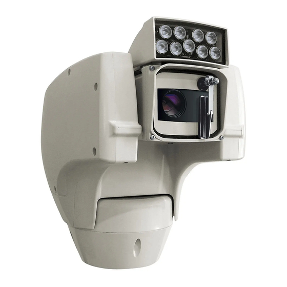
5.2 LED illuminator 5 Versions The pan & tilt can be fitted with a LED illuminator. 5.1 Integrated wiper The product can be fitted with a wiper. Fig. 4 Fig. 3 For further information refer to the relative chapter (9.2.2 User Controls, page 23). For further information refer to the relative chapter (9.2.2 User Controls, page 23). -
Page 14: Preparing The Product For Use
6.2 Unpacking and contents 6 Preparing the product for 6.2.1 Unpacking When the product is delivered, make sure that the Any change that is not expressly approved package is intact and that there are no signs that it by the manufacturer will invalidate the has been dropped or scratched. -
Page 15: Preparatory Work Before Installation
6.4 Preparatory work before 7 Assembling and installing installation The assembly and installation must be performed only by skilled personnel. 6.4.1 Attaching the bracket Different types of supports are available (10 This is a Class A product. In a domestic Accessories, page 31). -
Page 16: Fixing The Base To The Support
7.1.2 Fixing the base to the support 7.1.3 Connection of the connector board Use the screws and the washers supplied with 7.1.3.1 Connector board description the base. BOARD DESCRIPTION After having positioned gasket (01), fasten base (02) on support (03) using screws (04), toothed spring Connector Function washers and the flat washers (05). -
Page 17: Connection Of The Power Supply Line
7.1.3.2 Connection of the power supply line Connect the power supply cables to the J2 terminal as described in the table. Electrical connections must be performed CONNECTION OF THE POWER SUPPLY LINE with the power supply disconnected and the circuit-breaker open. Colour Terminals Power supply 24Vac... -
Page 18: Connection Of The Secondary Connector Board
7.1.4 Connection of the secondary 7.1.4.2 Connection of the alarm inputs connector board In case of free contact alarm make the connection as shown in the figure. 7.1.4.1 Description of the secondary board The alarm contacts are present on connector J4. BOARD DESCRIPTION Connector Function... -
Page 19: Relay Connection
7.1.4.3 Relay connection 7.1.4.5 Connection of the Ethernet cable The relay can be used for low working Connect the J1 connector of the secondary connector voltages only (up to 30Vac or 60Vdc) and with board using a 5E category, or higher, UTP cable ( a maximum current of 1A. -
Page 20: Fixing The Upper Body
7.2 Hardware configuration 7.1.5 Fixing the upper body Point the self-centering connector (01) of the upper 7.2.1 Opening the configuration door unit. Point the side set (02) so that it faces the frontal vision of the camera. Position the upper part on the Before powering the device, this must be configured base in the same direction shown in the figure. -
Page 21: Configuration Of The Dip-Switches
7.2.2 Configuration of the dip-switches 8 Switching on When the dip-switch rocker (SW) is up it The automatic pre-heating (De-Ice) process represents the value 1 (ON) while if it is down could be started whenever the device is it represents the value 0 (OFF). switched on and the air temperature is below 0°C. -
Page 22: Configuration
9 Configuration The Pan & Tilt control interface is displayed if login is successful. The product can be configured using one of the following tools: • Sofware interface: Configuration via the application installed on PC. • Web interface: Configuration via the browser. 9.1 Sofware interface 9.1.1 Minimum system requirements The supplied Pan &... - Page 23 Click Add. The camera will be available in the device list (Camera list) and can be displayed by dragging-and-dropping the icon onto one of the squares not used. Fig. 25 Fig. 23 To display the cameras on different computers, install Assign a name to the camera and to the unit.
-
Page 24: Web Interface
9.2 Web interface A window appears to add the servers to which connect to by pressing the Add button. During the first connection assign an address other than 192.168.10.100. Browsers supported: Microsoft Internet Explorer, Google Chrome, Mozilla Firefox. The first operation in configuring the P&T unit consists in connecting to the web interface. -
Page 25: User Controls
9.2.2 User Controls • Focus far/Focus near To control the Pan & Tilt through the browser, select the User Control entry. A new window will open with a virtual keyboard to enter commands. Fig. 33 • Wiper/Washer Fig. 34 • Day: Activate the camera's IR filter. If available, it turns off the LED illuminators. -
Page 26: Device Parameters
9.2.3 Device Parameters 9.2.5 Network Configuration From menu entry Device Parameters it is possible From menu entry Network Configuration it is possible to set the name of the pan & tilt and view other to change the setting of the Pan & Tilt network. It is additional information. -
Page 27: User Configuration
9.2.6 User Configuration • Autoflip: Turn the Pan & Tilt by 180° when the tilt of the Pan & Tilt reaches the end run. It makes it From menu entry User Configuration it is possible easier tracking subjects along corridors or roads. to administer all users that have access to Pan &... -
Page 28: Autopan
9.2.7.1 Autopan 9.2.7.3 Motions Recall In the Autopan subsection it is possible to specify the In the Motion Recall subsection it is possible to preset autopan start and end.. specify a time interval of inactivity after which Pan & Tilt will carry out one of the following functions: It is possible to set the speed with which the distance return to Home position, start autopan or start patrol. -
Page 29: Preset Parameters
9.2.8 Preset Parameters 9.2.9 Preset Parameters (Advanced) From menu entry Preset Parameters a number of In the Preset Parameters (Advanced) section it is parameters relative to the presets can be configured: possible to customise the speed and pause values for each preset, in addition to enabling/disabling the •... -
Page 30: Digital I/O
9.2.10 Digital I/O 9.2.11 Wiper In the Digital I/O tab it is possible to configure the Do not use the wiper when the outside digital channels available in Pan & Tilt. What follows is temperature is below 0°C or in case of ice. a brief description of the configurable parameters for each digital input. -
Page 31: Encoder Parameters
9.2.13 Encoder Parameters 9.2.14 Camera Parameters The 2 video streams can be configured under The camera integrated in the Pan & Tilt can be the Encoder Parameters menu. The first stream configured under the Camera Parameters menu: is compulsorily compressed with the H.264/AVC •... -
Page 32: Tools
9.2.15 Tools • Other: It allows setting other values: Image Mirror, Noise Reduction, Wide Dynamic (Visibility From menu entry Tools it is possible to re-set the Enhancer), High Resolution, Aperture Control, predefined values for the entire configuration of Pan Defog, Highlight Correction. &... -
Page 33: Accessories
10.3 Parapet bracket 10 Accessories Parapet bracket with internal cable channel. For further details on configuration and use, refer to the relative manual. 10.1 Washer If the pan & tilt is fitted with a wiper, it can also have an external pump supplying water to clean the glass. Fig. -
Page 34: Instructions For Normal Operation
11 Instructions for normal operation 11.1 Special controls SPECIAL CONTROLS Control Protocol TCAM ONVIF (auxiliary command) Wiper Start Save Preset 85 tt:Wiper|On Wiper Stop Save Preset 86 tt:Wiper|Off Washer Save Preset 87 tt:WashingProcedure|On Night Mode On Save Preset 88 tt:IRLamp|On Night Mode Off Save Preset 89 tt:IRLamp|Off... -
Page 35: Maintaining And Cleaning
12.2 Cleaning 12 Maintaining and cleaning The pan & tilt devices require no particular maintenance. To clean the device use neutral 12.1 Maintaining detergent and a non-abrasive cloth. Remember that the device is waterproof. 12.2.1 Window and plastic cover Maintenance must be carried out by personnel trained to operate on electrical cleaning circuits. -
Page 36: Disposal Of Waste Materials
13 Disposal of waste 14 Troubleshooting materials Ask for assistance from skilled personnel if: • The unit is damaged after being dropped; This symbol mark and recycle system are • There is noticeable deterioration in performance applied only to EU countries and not applied of the unit. -
Page 37: Technical Data
15.3 Camera 15 Technical data Day/Night Full HD 30x CDS installation type (Cable Distribution Image Device: 1/2.8 type Exmor™ CMOS sensor System). The installation is type TNV-1, do not connect it to SELV circuits. Effective Pixels: approx. 2.38 Megapixels Minimum Illumination: CAUTION! In order to reduce the risk of fire, •... -
Page 38: Video
15.4 Video 15.6 Network Compression: H.264/AVC, MJPEG Connection Ethernet port LAN 10/100T 2 independent video streams Full HD or 4 15.7 Network protocols independent video streams depending on the configuration ONVIF, Profile S Image resolution: from FullHD to 352x240 in 18 steps For device configuration: TCP/IPv4, UDP/IPv4, HTTP, NTP, DHCP, WS-DISCOVERY Selectable frame rate from 1 to 60 images per second... -
Page 39: Technical Drawings
16 Technical drawings The dimensions of the drawings are in millimetres. Fig. 57 ULISSE COMPACT HD. MNVCUCHD_1511_EN... - Page 40 Fig. 58 ULISSE COMPACT HD with LED illuminator. MNVCUCHD_1511_EN...
- Page 42 Headquarters Italy Videotec S.p.A. France Videotec France SARL Via Friuli, 6 - I-36015 Schio (VI) - Italy Immeuble Le Montreal, 19bis Avenue du Québec, ZA de Courtaboeuf Tel. +39 0445 697411 - Fax +39 0445 697414 91140 Villebon sur Yvette - France Email: info@videotec.com Tel.
- Page 43 ULISSE COMPACT HD Telecamera PTZ da esterni per dettagliate immagini Full HD e alte prestazioni Italiano - Manuale di istruzioni...
- Page 45 Sommario ITALIANO 1 Informazioni sul presente manuale ................7 1.1 Convenzioni tipografiche ............................. 7 2 Note sul copyright e informazioni sui marchi commerciali ........7 3 Norme di sicurezza ......................7 4 Identificazione ......................10 4.1 Descrizione e designazione del prodotto .....................10 4.2 Marcatura del prodotto ............................10 4.2.1 Controllo della marcatura ..............................10 5 Versioni .........................
- Page 46 9.1.2 Procedura di configurazione tramite software ......................20 9.1.3 Installazione del software ..............................20 9.2 Interfaccia web ...............................22 9.2.1 Home ......................................22 9.2.2 Controlli Utente ..................................23 9.2.3 Parametri Dispositivo ................................24 9.2.4 Statistiche Dispositivo................................24 9.2.5 Configurazione Rete ................................24 9.2.6 Configurazione Utenti .................................25 9.2.7 Parametri Movimento ................................25 9.2.7.1 Autopan .........................................26 9.2.7.2 Patrol ..........................................26 9.2.7.3 Richiamo Movimenti ....................................26...
- Page 47 15.9 Certificazioni .................................36 16 Disegni tecnici ......................37 MNVCUCHD_1511_IT...
- Page 48 MNVCUCHD_1511_IT...
-
Page 49: Informazioni Sul Presente Manuale
1 Informazioni sul presente 3 Norme di sicurezza manuale Radiazione LED infrarossa. Non guardare l'illuminatore direttamente utilizzando Prima di installare e utilizzare questa unità, leggere strumenti ottici. Apparecchio LED di Classe attentamente questo manuale. Conservare questo 1M. Potenza ottica emessa a 0.1m: 2.2mW @ manuale a portata di mano come riferimento futuro. - Page 50 • La categoria di installazione (detta anche categoria ATTENZIONE! L'installazione è di tipo TNV-1. di sovratensione) specifica i livelli della tensione Non collegare a circuiti SELV. transitoria di rete alla quale l’apparato è soggetto. La categoria dipende dal luogo di installazione ATTENZIONE! Per assicurare la protezione e dalla presenza di dispositivi di protezione contro il rischio di incendio, sostituire i...
- Page 51 • Collegare il dispositivo ad una sorgente • La manutenzione del dispositivo deve essere d’alimentazione corrispondente a quella indicata eseguita solo da personale qualificato. Durante le nell’etichetta di marcatura. Prima di procedere operazioni di manutenzione l'operatore è esposto con l’installazione verificare che la linea elettrica al rischio di folgorazione o ad altri pericoli.
-
Page 52: Identificazione
4.2 Marcatura del prodotto 4 Identificazione 4.1 Descrizione e designazione Sui brandeggi è applicata una etichetta conforme alla marcatura CE. del prodotto ULISSE COMPACT HD è una telecamera PTZ Full HD di rete, IP66, che fornisce immagini di ottima qualità ad alta definizione. -
Page 53: Versioni
5.2 Illuminatore a LED 5 Versioni Il brandeggio può essere provvisto di un illuminatore 5.1 Tergicristallo integrato a LED. Il prodotto può essere provvisto di tergicristallo. Fig. 4 Fig. 3 Per ulteriori informazioni fare riferimento Per ulteriori informazioni fare riferimento al relativo capitolo (9.2.2 Controlli Utente, al relativo capitolo (9.2.2 Controlli Utente, pagina 23). -
Page 54: Preparazione Del Prodotto Per L'utilizzo
6.2 Disimballaggio e contenuto 6 Preparazione del prodotto per l'utilizzo 6.2.1 Disimballaggio Alla consegna del prodotto verificare che l'imballo Qualsiasi cambiamento non espressamente sia integro e non abbia segni evidenti di cadute o approvato dal costruttore fa decadere la abrasioni. garanzia. -
Page 55: Lavoro Preparatorio Prima Dell'installazione
6.4 Lavoro preparatorio prima 7 Assemblaggio e dell’installazione installazione 6.4.1 Fissaggio del supporto L'assemblaggio e l'installazione vanno Sono disponibili diversi tipi di supporto (10 eseguiti solo da personale qualificato. Accessori, pagina 31). Scegliere il supporto adeguato all'installazione e seguire tutte le istruzioni nel Questo è... -
Page 56: Fissaggio Della Base Al Supporto
7.1.2 Fissaggio della base al supporto 7.1.3 Collegamento della scheda connettori Utilizzare le viti e le rondelle fornite con la 7.1.3.1 Descrizione della scheda connettori base. DESCRIZIONE DELLA SCHEDA Dopo aver posizionato la guarnizione (01), fissare la base (02) sul supporto (03) utilizzando le viti (04), le Connettore Funzione rondelle dentellate e rondelle piane (05). -
Page 57: Collegamento Della Linea Di Alimentazione
7.1.3.2 Collegamento della linea di Collegare i cavi di alimentazione al morsetto J2 come descritto in tabella. alimentazione COLLEGAMENTO DELLA LINEA DI ALIMENTAZIONE Eseguire le connessioni elettriche in assenza Colore Morsetti di alimentazione e con dispositivo di sezionamento aperto. Alimentazione 24Vac Definito dall'installatore N (Neutro) All’atto dell’installazione controllare che... -
Page 58: Collegamento Della Scheda Connettori Secondaria
7.1.4 Collegamento della scheda 7.1.4.2 Collegamento degli ingressi di allarme connettori secondaria Nel caso di allarme a contatto pulito eseguire il 7.1.4.1 Descrizione della scheda secondaria collegamento come illustrato in figura. DESCRIZIONE DELLA SCHEDA I contatti degli allarmi sono presenti sul connettore Connettore Funzione Connettore Ethernet... -
Page 59: Collegamento Dei Relè
7.1.4.3 Collegamento dei relè 7.1.4.5 Collegamento del cavo di rete Ethernet Il relè è utilizzabile solamente per basse tensioni di lavoro (fino a 30Vac oppure 60Vdc) Collegare il connettore J1 della scheda connettori e con una corrente massima di 1A. Utilizzare secondaria tramite un cavo UTP di categoria 5E cavi di sezione idonea al carico da controllare o superiore (7.1.4.1 Descrizione della scheda... -
Page 60: Fissaggio Del Corpo Superiore
7.2 Configurazione hardware 7.1.5 Fissaggio del corpo superiore Orientare il connettore autocentrante (01) dell'unità 7.2.1 Apertura dello sportellino di superiore. Orientare la sporgenza laterale (02) nel configurazione senso di visione frontale della telecamera. Posizionare l'unità superiore sulla base con l'orientamento Prima di alimentare il dispositivo è... -
Page 61: Configurazione Dei Dip-Switch
7.2.2 Configurazione dei dip-switch 8 Accensione La levetta del dip-switch (SW) verso l'alto La procedura di preriscaldamento automatico rappresenta il valore 1 (ON) mentre la levetta (De-Ice) si potrebbe attivare tutte le volte verso il basso rappresenta il valore 0 (OFF). che il dispositivo viene acceso ad una temperatura ambiente inferiore a 0°C. -
Page 62: Configurazione
9 Configurazione Se il login viene effettuato con successo, verrà mostrata l'interfaccia di gestione del brandeggio La configurazione del prodotto può essere effettuata utilizzando uno dei seguenti strumenti: • Interfaccia software: Configurazione tramite applicazione installata su PC. • Interfaccia web: Configurazione tramite browser. 9.1 Interfaccia software 9.1.1 Requisiti minimi del PC Il software di gestione dei brandeggi fornito in... - Page 63 Cliccare il tasto Add. La telecamera sarà disponibile nell'elenco dei dispositivi (Camera list) e potrà essere visualizzata effettuando un drag and drop dell'icona su uno dei riquadri non utilizzati. Fig. 23 Fig. 25 Assegnare un nome alla telecamera ed al gruppo. Per visualizzare le telecamere su più...
-
Page 64: Interfaccia Web
9.2 Interfaccia web Verrà visualizzata una finestra dove sarà possibile aggiungere i server cui collegarsi premendo il bottone Add. Alla prima connessione assegnare un indirizzo diverso da 192.168.10.100. Browser supportati: Microsoft Internet Explorer, Google Chrome, Mozilla Firefox. La prima operazione per configurare il brandeggio consiste nel connettersi alla sua interfaccia web. -
Page 65: Controlli Utente
9.2.2 Controlli Utente • Focus far/Focus near Per controllare il brandeggio via browser, selezionare la voce Controlli Utente. Si aprirà una nuova finestra con una tastiera virtuale per inviare i comandi. Fig. 33 • Wiper/Washer Fig. 34 • Day: Attiva il filtro IR della camera. Se presenti, spegne gli illuminatori a LED. -
Page 66: Parametri Dispositivo
9.2.3 Parametri Dispositivo 9.2.5 Configurazione Rete Alla voce del menu Parametri Dispositivo è possibile Alla voce del menu Configurazione Rete è possibile impostare il nome del brandeggio e visualizzare altre cambiare l'impostazione di rete del brandeggio. È informazioni aggiuntive. possibile decidere se il dispositivo debba avere un indirizzo assegnato staticamente o dinamicamente con DHCP. -
Page 67: Configurazione Utenti
9.2.6 Configurazione Utenti • Autoflip: Ruota il brandeggio di 180° quando il tilt del brandeggio arriva a fine corsa. Facilita Alla voce del menu Configurazione Utenti è possibile l’inseguimento di soggetti lungo corridoi o strade. amministrare gli utenti che possono accedere al •... -
Page 68: Autopan
9.2.7.1 Autopan 9.2.7.3 Richiamo Movimenti Nella sottosezione Autopan e possibile specificare il Nella sottosezione Richiamo Movimenti è possibile preset di inizio e di fine dell'autopan. specificare un intervallo di tempo di inattività terminato il quale il brandeggio provvederà ad È possibile impostare le velocità con cui coprire il eseguire una delle seguenti funzioni: ritorno alla tragitto. -
Page 69: Parametri Preset
9.2.8 Parametri Preset 9.2.9 Parametri Preset (Avanzato) Alla voce del menu Parametri Preset sono Nella sezione Parametri Preset (Avanzato) è possibile configurabili alcuni parametri relativi ai preset: personalizzare i valori di velocità e pausa per ciascun preset, oltre che ad abilitare/disabilitare i preset •... -
Page 70: I/O Digitali
9.2.10 I/O Digitali 9.2.11 Wiper Nella scheda I/O Digitali è possibile configurare i Non utilizzare il tergicristallo quando la canali digitali presenti nel brandeggio. Segue una temperatura esterna è inferiore a 0°C o in breve descrizione dei parametri configurabili per presenza di ghiaccio. -
Page 71: Parametri Encoder
9.2.13 Parametri Encoder 9.2.14 Parametri Camera Alla voce del menù Parametri Encoder è possibile Alla voce del menu Parametri Camera è possibile configurare i 2 flussi video del dispositivo. Il configurare la telecamera integrata nel brandeggio: primo flusso è obbligatoriamente compresso con •... -
Page 72: Strumenti
9.2.15 Strumenti • Altro: Permette di impostare altri valori: Immagine Speculare, Riduzione Rumore, Wide Dynamic Alla voce del menu Strumenti è possibile reimpostare (Visibility Enhancer), Alta Risoluzione, Controllo i valori predefiniti per tutta la configurazione del Apertura, Defog, Correzione Sovraesposizione. brandeggio o solo per alcune sezioni specifiche. -
Page 73: Accessori
10.3 Supporto da parapetto 10 Accessori Supporto per montaggio a parapetto con passaggio Per ulteriori dettagli sulla configurazione interno cavi. e l’utilizzo fare riferimento al manuale del relativo accessorio. 10.1 Impianto di lavaggio Il brandeggio, se provvisto di tergicristallo, può essere dotato di una pompa esterna che fornisce acqua per la pulizia del vetro. -
Page 74: Istruzioni Di Funzionamento Ordinario
11 Istruzioni di funzionamento ordinario 11.1 Comandi speciali COMANDI SPECIALI Comando Protocollo TCAM ONVIF (auxiliary command) Wiper Start Salvare Preset 85 tt:Wiper|On Wiper Stop Salvare Preset 86 tt:Wiper|Off Washer Salvare Preset 87 tt:WashingProcedure|On Modalità Notturna On Salvare Preset 88 tt:IRLamp|On Modalità... -
Page 75: Manutenzione E Pulizia
12.2 Pulizia 12 Manutenzione e pulizia I brandeggi non necessitano di particolare 12.1 Manutenzione manutenzione. Per la pulizia del dispositivo utilizzare detergenti neutri e panni non abrasivi. Si ricorda che La manutenzione deve essere eseguita solo il dispositivo è impermeabile. da personale qualificato ad intervenire su 12.2.1 Pulizia del vetro e delle parti in circuiti elettrici. -
Page 76: Smaltimento Dei Rifiuti
13 Smaltimento dei rifiuti 14 Risoluzione dei problemi Richiedere l’intervento di personale qualificato Questo simbolo e il sistema di riciclaggio quando: sono validi solo nei paesi dell'EU e non • L’unità si è danneggiata a seguito di una caduta; trovano applicazione in altri paesi del mondo. •... -
Page 77: Dati Tecnici
15.3 Telecamera 15 Dati tecnici Day/Night Full HD 30x L'impianto è di tipo CDS (Cable Distribution Sensore di immagine: 1/2.8 type Exmor™ CMOS System). Non collegare a circuiti SELV. sensor ATTENZIONE! Per ridurre il rischio di incendio Pixels Effettivi: appross. 2.38 Megapixel usare solamente cavi aventi sezioni maggiori Illuminazione Minima: o uguali a 0.13mm²... -
Page 78: Video
15.4 Video 15.6 Rete Compressione: H.264/AVC, MJPEG Connessione porta Ethernet LAN 10/100T 2 flussi video indipendenti Full HD oppure 4 flussi 15.7 Protocolli di rete video indipendenti a seconda della configurazione ONVIF, Profilo S Risoluzione immagine: da FullHD a 352x240 in 18 passi Per la configurazione del dispositivo: TCP/IPv4, UDP/ IPv4, HTTP, NTP, DHCP, WS-DISCOVERY... -
Page 79: Disegni Tecnici
16 Disegni tecnici Le dimensioni dei disegni sono espresse in millimetri. Fig. 57 ULISSE COMPACT HD. MNVCUCHD_1511_IT... - Page 80 Fig. 58 ULISSE COMPACT HD con illuminatore a LED. MNVCUCHD_1511_IT...
- Page 82 Headquarters Italy Videotec S.p.A. France Videotec France SARL Via Friuli, 6 - I-36015 Schio (VI) - Italy Immeuble Le Montreal, 19bis Avenue du Québec, ZA de Courtaboeuf Tel. +39 0445 697411 - Fax +39 0445 697414 91140 Villebon sur Yvette - France Email: info@videotec.com Tel.
- Page 83 ULISSE COMPACT HD Caméra PTZ extérieure pour images détaillées en Full HD et hautes performances Français - Manuel d’instructions...
- Page 85 Sommaire FRANÇAIS 1 À propos de ce mode d’emploi ..................7 1.1 Conventions typographiques ..........................7 2 Notes sur le copyright et informations sur les marques de commerce ..... 7 3 Normes de securité ......................7 4 Identification ........................ 10 4.1 Description et désignation du produit ......................10 4.2 Marquage du produit ............................10 4.2.1 Contrôle du marquage ................................10...
- Page 86 9.1.2 Procédure de configuration par l'intermédiaire du logiciel ...................20 9.1.3 Installation du logiciel ................................20 9.2 Interface web ................................22 9.2.1 Home ......................................22 9.2.2 Contrôles Utilisateur ................................23 9.2.3 Paramètres Dispositif ................................24 9.2.4 Statistiques Dispositif ................................24 9.2.5 Configuration Réseau................................24 9.2.6 Configuration Utilisateurs ..............................25 9.2.7 Paramètres Mouvement ..............................25 9.2.7.1 Autopan .........................................26 9.2.7.2 Patrol ..........................................26...
- Page 87 15.9 Certifications .................................36 16 Dessins techniques ....................37 MNVCUCHD_1511_FR...
- Page 88 MNVCUCHD_1511_FR...
-
Page 89: Propos De Ce Mode D'emploi
1 À propos de ce mode 3 Normes de securité d’emploi Radiation LED infrarouge. Ne pas regarder directement le projecteur en utilisant des Avant d’installer et d’utiliser cet appareil, veuillez instruments optiques. Appareil LED de lire attentivement ce mode d’emploi. Conservez-le à Classe 1M. - Page 90 • La catégorie d’installation (ou catégorie de ATTENTION! L'installation est du type TNV-1. surtension) spécifie les niveaux de la tension de Ne pas la connecter à des circuits SELV. secteur correspondant à l’appareil. La catégorie dépend du lieu d’installation et du dispositif ATTENTION! Pour assurer la protection contre de protection contre les surtensions installé.
- Page 91 • Raccorder le système à une source d'alimentation • L'entretien du dispositif doit uniquement être conforme à celle figurant sur l'étiquette de effectué par un personnel qualifié. Durant les marquage du produit. Avant de procéder à opérations d'entretien, l'opérateur est exposé au l'installation, vérifier que la ligne électrique est risque d'électrocution ou autres.
-
Page 92: Identification
4.2 Marquage du produit 4 Identification 4.1 Description et désignation du Les tourelles portent un étiquette conforme au marquage CE. produit ULISSE COMPACT HD est une caméra PTZ réseau FullHD IP66 qui offre une excellente qualité en haute défnition des images. La caméra Full HD intègre un zoom optique 30x et est en mesure d'identifer avec précision des détails spécifiques d'une scène. -
Page 93: Versions
5.2 Projecteur à LED 5 Versions La tourelle peut être équipée d’un projecteur à LED. 5.1 Essuie-glace intégré Le produit peut être munie d’un essuie-glace. Fig. 4 Fig. 3 Pour d'autres renseignements se référer à le chapitre relatif (9.2.2 Contrôles Utilisateur, Pour d'autres renseignements se référer à... -
Page 94: Préparation Du Produit En Vue De L'utilisation
6.2 Déballage et contenu 6 Préparation du produit en vue de l’utilisation 6.2.1 Déballage Lors de la livraison du produit, vérifier que Toute modification non approuvée l’emballage est en bon état et l’absence de tout signe expressément par le fabricant entraînera évident de chute ou d’abrasion. -
Page 95: Opérations À Effectuer Avant L'installation
6.4 Opérations à effectuer avant 7 Assemblage et l’installation installation 6.4.1 Fixation du support L’assemblage et l’installation doivent être Plusieurs types de supports sont disponibles (10 effectués par un personnel qualifié. Accessoires, page 31). Choisir le support convenable à l'installation et suivre toutes les instrucions dans le Ce produit appartient à... -
Page 96: Fixage De La Base Au Support
7.1.2 Fixage de la base au support 7.1.3 Connexion de la carte de connexion Utiliser les vis et les rondelles fournies avec 7.1.3.1 Description de la carte de connexion la base. DESCRIPTION DE LA CARTE Après avoir installé la garniture (01), fixer la base (02) sur son support (03) au moyen des vis (04), des Connecteur Fonction... -
Page 97: Connexion De La Ligne D'alimentation
7.1.3.2 Connexion de la ligne d'alimentation Connecter les câbles d'alimentation au borne J2 comme décrit dans le tableau. Il faut effectuer les connexions électriques CONNEXION DE LA LIGNE D'ALIMENTATION en absence d'alimentation et lorsque le dispositif de sectionnement ouvert. Couleur Bornes Alimentation 24Vac Contrôler que les sources d'alimentation et... -
Page 98: Connexion De La Carte Secondaire Des Connecteurs
7.1.4 Connexion de la carte secondaire 7.1.4.2 Connexion des entrées de l'alarme des connecteurs Dans le cas d'une alarme à contact propre, effectuer la connexion comme indiqué sur l'image. 7.1.4.1 Description de la carte secondaire Les contacts des alarmes sont présents sur le DESCRIPTION DE LA CARTE connecteur J4. -
Page 99: Branchement Des Relais
7.1.4.3 Branchement des relais 7.1.4.5 Branchement du câble de réseau Ethernet Le relais est utilisable uniquement pour les basses tensions de travail (jusqu'à 30Vac Connecter le connecteur J1 à la carte secondaire des ou 60Vdc) et avec un courant maximal de connecteurs à... -
Page 100: Fixation Du Corps Supérieur
7.2 Configuration du matériel 7.1.5 Fixation du corps supérieur Orienter le connecteur autocentrant (01) de l’unité 7.2.1 Ouverture du volet de supérieure. Orienter la saillie latérale (02) dans le sens configuration de vision frontale de la caméra. Positionner l’unité supérieure sur la base selon l’orientation représentée Avant mettre le dispositif sous tension le configurer sur la figure. -
Page 101: Configuration Des Dip-Switch
7.2.2 Configuration des dip-switch 8 Allumage Le levier du dip-switch (SW) vers le haut La procédure de préchauffage automatique représente la valeur 1 (ON) tandis que le (De-Ice) peut être activée chaque fois levier vers le bas représente la valeur 0 (OFF). que le dispositif est mis en fonction à... -
Page 102: Configuration
9 Configuration Si le login est effectué avec succès, on pourra voir l'interface de gestion de la tourelle La configuration du produit peut être effectuée en utilisant un des instruments suivants: • Logiciel OSM: Configuration à l'aide d'une application installée sur le PC •... - Page 103 Cliquer sur la touche Add. La caméra sera disponible dans la liste des dispositifs (Camera list) et pourra être affichée en effectuant un drag and drop de l'icône sur l'un des encadrés non utilisés. Fig. 23 Fig. 25 Attribuer un nom à la caméra et au groupe. Pour afficher les caméras sur plusieurs ordinateurs Sélectionner le protocole ONVIF ou TCAM et il faut installer le TVMS client et l'utiliser pour...
-
Page 104: Interface Web
9.2 Interface web Une fenêtre où il sera possible d'ajouter les serveurs auxquels se raccorder s'affichera en appuyant sur le bouton Add. À la première connexion, donner une adresse différente de 192.168.10.100. Logiciels de navigation supportés: Microsoft Internet Explorer, Google Chrome, Mozilla Firefox. -
Page 105: Contrôles Utilisateur
9.2.2 Contrôles Utilisateur • Focus far/Focus near Pour contrôler la tourelle par navigateur, sélectionner la mention Contrôle Utilisateur. Une nouvelle fenêtre s'ouvrira, avec un clavier virtuel pour sélectionner les commandes. Fig. 33 • Wiper/Washer Fig. 34 • Day: Activer le filtre IR de la chambre. Si présents, éteint les projecteurs à... -
Page 106: Paramètres Dispositif
9.2.3 Paramètres Dispositif 9.2.5 Configuration Réseau A la mention du menu Paramètres Dispositif il est A la mention du menu Configuration Réseau il est possible de configurer le nom de la tourelle et possible de changer la configuration de réseau de d'afficher d'autres informations supplementaire. -
Page 107: Configuration Utilisateurs
9.2.6 Configuration Utilisateurs • Autoflip: Tourne la tourelle de 180 ° lorsque le tilt de la tourelle arrive en fin de course. Il facilité la A la mention du menu Configuration Utilisateurs poursuite des sujets long de couloirs ou de rues. il est possible d'administrer les utilisateurs qui •... -
Page 108: Autopan
9.2.7.1 Autopan 9.2.7.3 Rappel Mouvements Dans la sous-section Autopan il est possible Dans la sous-section Rappel Mouvements il est d'indiquer le preset de début et de fin de l'autopan. possible d'indiquer un intervalle de temps d'inactivité au-delà duquel la tourelle effectuera une des suivants Il est possible de configurer la vitesse à... -
Page 109: Paramètres Preset
9.2.8 Paramètres Preset 9.2.9 Paramètres Preset (Avancé) A la mention du menu Paramètres Preset on peut Dans la section Paramètres Preset (Avancé) il est configurer certains paramètres concernant les preset: possible de personnaliser les valeurs de vitesse et pause pour chaque preset, en plus que d'activer/ •... -
Page 110: I/O Digitaux
9.2.10 I/O Digitaux 9.2.11 Wiper Dans la carte I/O Digitaux il est possible de configurer Ne pas utiliser l’essuie-glace lorsque la les canaux digitaux présents dans la tourelle. Il y a température extérieure est inférieure à 0°C ci-dessous une courte description des paramètres ou en cas de givre. -
Page 111: Paramètres Encoder
9.2.13 Paramètres Encoder 9.2.14 Paramètres Caméra Au poste du menu Paramètres Encoder il est possible Dans le menu Paramètres Caméra il est possible de de configurer les 2 flux vidéo du dispositif. Le premier configurer la caméra intégrée au socle de pointage: flux est obligatoirement comprimé... -
Page 112: Instruments
9.2.15 Instruments • Autre: Cela permet d'installer d'autres valeurs: Image Renversée, Noise Reduction, Wide Dynamic A la mention du menu Instruments il est possible (Visibility Enhancer), Haute Resolution, Contrôle De de reconfigurer les valeurs prédéfinies pour toute L'ouverture, Defog, Correction De La Surexposition. la configuration de la tourelle ou seulement pour certaines sections spécifiques. -
Page 113: Accessoires
10.3 Support fixation sol 10 Accessoires Support de fixation au sol avec passage interne des Pour de plus amples informations sur la câbles. configuration et l'utilisation, consulter le manuel de l'accessoire correspondant. 10.1 Système de lavage La tourelle, si elle est munie d’un essuie-glace, peut aussi être équipée d’une pompe externe qui fournit l’eau pour le nettoyage de la glace. -
Page 114: Instructions De Fonctionnement Courant
11 Instructions de fonctionnement courant 11.1 Commandes spéciales COMMANDES SPÉCIALES Commande Protocole TCAM ONVIF (auxiliary command) Wiper Start Sauver Preset 85 tt:Wiper|On Wiper Stop Sauver Preset 86 tt:Wiper|Off Washer Sauver Preset 87 tt:WashingProcedure|On Modalité Nocturne On Sauver Preset 88 tt:IRLamp|On Modalité... -
Page 115: Entretien Et Nettoyage
12.2 Nettoyage 12 Entretien et nettoyage Les tourelles n'exigent aucun entretien particulier. 12.1 Entretien Pour le nettoyage de l'appareil, utiliser des détergents neutres et des chiffons non abrasifs. Le dispositif est L’entretien doit être uniquement effectué par imperméable. un personnel qualifié en matière de circuits 12.2.1 Entretiens de la vitre et des électriques. -
Page 116: Élimination Des Déchets
13 Élimination des déchets 14 Dépannage Demander l'intervention d'un personnel qualifié dans Ce symbole et le système de recyclage ne sont les cas suivants: appliqués que dans les pays UE et non dans • L'unité est endommagée à la suite d'une chute; les autres pays du monde. -
Page 117: Données Techniques
15.3 Caméra 15 Données techniques Day/Night Full HD 30x L'installation est du type CDS (Cable Capteur d'image: 1/2.8 type Exmor™ CMOS sensor Distribution System). Ne pas la connecter à des circuits SELV. Pixels effectifs: environ 2.38 Megapixel Illumination minimum: ATTENTION! Pour réduire les risques •... -
Page 118: Vidéo
15.4 Vidéo 15.6 Réseau Compression: H.264/AVC, MJPEG Connection sortie Ethernet LAN 10/100T 2 flux vidéo indépendants Full HD ou 4 flux vidéo 15.7 Protocoles réseau indépendants en fonction de la configuration ONVIF, Profil S Résolution de l’image: de FullHD à 352x240 en 18 étapes Pour configuration du dispositif: TCP/IPv4, UDP/IPv4, HTTP, NTP, DHCP, WS-DISCOVERY... -
Page 119: Dessins Techniques
16 Dessins techniques Les dimensions des dessins sont exprimées en millimètres. Fig. 57 ULISSE COMPACT HD. MNVCUCHD_1511_FR... - Page 120 Fig. 58 ULISSE COMPACT HD avec projecteur à LED. MNVCUCHD_1511_FR...
- Page 122 Headquarters Italy Videotec S.p.A. France Videotec France SARL Via Friuli, 6 - I-36015 Schio (VI) - Italy Immeuble Le Montreal, 19bis Avenue du Québec, ZA de Courtaboeuf Tel. +39 0445 697411 - Fax +39 0445 697414 91140 Villebon sur Yvette - France Email: info@videotec.com Tel.
- Page 123 ULISSE COMPACT HD PTZ Kamera für den Außenbereich für detaillierte Full HD-Bilder und High-Performance Deutsch - Bedienungslanleitung...
- Page 125 Inhaltsverzeichnis DEUTSCH 1 Allgemeines ........................7 1.1 Schreibweisen ................................7 2 Anmerkungen zum Copyright und Informationen zu den Handelsmarken ..... 7 3 Sicherheitsnormen ......................7 4 Identifizierung ......................10 4.1 Beschreibung und Bezeichnung des Produktes ..................10 4.2 Kennzeichnung des Produkts..........................10 4.2.1 Prüfung der Kennzeichnung .............................10 5 Versionen........................
- Page 126 9.1.2 Konfigurationsvorgang über Software ..........................20 9.1.3 Installation der Software ..............................20 9.2 Web-Schnittstelle ..............................22 9.2.1 Home ......................................22 9.2.2 Benutzersteuerung ................................23 9.2.3 Geräteparameter ...................................24 9.2.4 Gerätestatistiken ..................................24 9.2.5 Netzwerk-Konfiguration ..............................24 9.2.6 Benutzer-Konfiguration ...............................25 9.2.7 Bewegungsparameter .................................25 9.2.7.1 Autopan .........................................26 9.2.7.2 Patrol ..........................................26 9.2.7.3 Bewegungsanforderung ..................................26 9.2.8 Preset-Parameter ...................................27 9.2.9 Preset-Parameter (Erweitert) .............................27...
- Page 127 15.9 Zertifizierungen ..............................36 16 Technische Zeichnungen................... 37 MNVCUCHD_1511_DE...
- Page 128 MNVCUCHD_1511_DE...
-
Page 129: Allgemeines
1 Allgemeines 3 Sicherheitsnormen Lesen Sie bitte vor dem Installieren und dem Infrarot LED-Abstrahlung. Nicht direkt in Verwenden dieses Gerätes die Bedienungsanleitung den Scheinwerfer sehen, wenn optische sorgfältig durch. Bewahren Sie sie zum späteren Instrumente verwendet werden. LED- Nachschlagen auf. Gerät der Klasse 1M. - Page 130 • Die Installationskategorie (auch als ACHTUNG! Die Anlage gehört zum Typ TNV-1. Überspannungskategorie bezeichnet) gibt Nicht an Kreisläufe SELV anschließen. den Pegel der Netzspannungsstöße an, denen die Ausrüstung ausgesetzt ist. Die Kategorie ACHTUNG! Damit ein ständiger Brandschutz hängt vom Installationsort der Ausrüstung garantiert wird, sind die Sicherungen nur und von den externen Schutzeinrichtungen in dem gleichen Typ und Wert zu ersetzen.
- Page 131 • Vorgeschrieben ist der Anschluss an eine • Die Wartung der Einrichtung ist Fachleuten Versorgungsquelle, deren Eigenschaften den vorbehalten. Während der Wartungsarbeiten ist die Angaben auf dem Kennzeichnungsschild tätige Person der Gefahr von Stromschlägen und entsprechen. Vor der Installation ist zu prüfen, ob anderen Gefahren ausgesetzt.
-
Page 132: Identifizierung
4.2 Kennzeichnung des Produkts 4 Identifizierung 4.1 Beschreibung und Auf den Schwenk-Neige-Köpfen befindet sich ein Schildchen, das der CE-Kennzeichnung Bezeichnung des Produktes entspricht. Die ULISSE COMPACT HD ist eine IP66 FullHD PTZ Netzwerkkamera, die ausgezeichnete High- Definition-Bildqualität liefert. Die Full HD Kamera enthält ein 30faches optisches Zoom und kann die Details einer Szene genau identifizieren. -
Page 133: Versionen
5.2 LED- Scheinwerfer 5 Versionen Der Schwenk-Neige-Kopf kann mit einem LED- 5.1 Vorinstallierter Wischer Scheinwerfer versehen sein. Das Produkt kann mit einem Scheibenwischer ausgestattet sein. Abb. 4 Abb. 3 Für weitere Infos bitte entsprechendes Kapitel beachten (9.2.2 Benutzersteuerung, Für weitere Infos bitte entsprechendes Seite 23). -
Page 134: Vorbereitung Des Produktes Auf Den Gebrauch
6.2 Entfernen der Verpackung 6 Vorbereitung des und Inhalt Produktes auf den Gebrauch 6.2.1 Entfernen der Verpackung Bei der Lieferung des Produktes ist zu prüfen, ob die Jede vom Hersteller nicht ausdrücklich Verpackung intakt ist oder offensichtliche Anzeichen genehmigte Veränderung führt zum Verfall von Stürzen oder Abrieb aufweist. -
Page 135: Auf Die Installation Vorbereitende Tätigkeiten
6.4 Auf die Installation 7 Zusammenbau und vorbereitende Tätigkeiten Installation 6.4.1 Befestigung der Halterung Zusammenbau und Installation sind Verschiedene Halterungen sind (10 Zubehör, Seite qualifizierten Fachleuten vorbehalten. 31). Das geeignetste für die Installation auswählen und alle Angaben aus diesem Kapitel befolgen. Dies ist ein Produkt der Klasse A. -
Page 136: Befestigung Der Basis An Der Halterung
7.1.2 Befestigung der Basis an der 7.1.3 Anschluss der Verbinderplatine Halterung 7.1.3.1 Beschreibung der Karte Anschlüsse Verwenden Sie die mit der Basis gelieferten BESCHREIBUNG DER KARTE Schrauben und Unterlegscheiben. Verbinder Funktion Platinenversorgung (V Nach der Positionierung der Dichtung (01) muss die Basis (02) auf der Halterung (03) befestigt Tab. -
Page 137: Anschluss Der Stromversorgung
7.1.3.2 Anschluss der Stromversorgung Die Versorgungskabel sind der J2 Klemme nach der Tabelle anzuschließen. Die elektrischen Anschlüsse nur durchführen, ANSCHLUSS DER STROMVERSORGUNG wenn die Stromversorgung abgetrennt und die Trennvorrichtung offen ist. Farbe Klemmen Netzteil 24Vac Im Zuge der Installation ist zu prüfen, Vom Installateur festgelegt. -
Page 138: Anschluss Der Sekundären Steckerkarte
7.1.4 Anschluss der sekundären 7.1.4.2 Anschluss der Alarmeingänge Steckerkarte Im Falle von Alarm mit potentialfreiem Kontakt muss der Anschluss gemäß der Abb. durchgeführt werden. 7.1.4.1 Beschreibung der sekundären Karte Die Kontakte der Alarme befinden sich am Verbinder BESCHREIBUNG DER KARTE Verbinder Funktion Ethernet Verbinder... -
Page 139: Anschluss Der Relais
7.1.4.3 Anschluss der Relais 7.1.4.5 Anschluss der Ethernet-Netz-Kabel Die Relais können nur für niedrige Stecker J1 der sekundären Steckerkarte mit einem Betriebsspannungen (bis zu 30Vac oder UTP Kabel anschließen, das mindestens zu der 60Vdc) verwendet werden und mit einem Kategorie 5E gehört. (7.1.4.1 Beschreibung der Höchststrom von 1A. -
Page 140: Befestigung Des Oberen Körpers
7.2 Hardware Konfiguration 7.1.5 Befestigung des oberen Körpers Den selbstzentrierenden Steckverbinder (01) der 7.2.1 Öffnen der Konfigurationsklappe oberen Einheit ausrichten. Den seitlichen Überstand (02) in die Blickrichtung der Videokamera ausrichten. Vor dem Einschalten des Gerätes muss es mit den Die obere Einheit auf der Basis mit der Ausrichtung DIP-schaltern im Batteriefach der Basis konfiguriert positionieren, wie in der Abbildung gezeigt. -
Page 141: Konfiguration Der Dipschalter
7.2.2 Konfiguration der Dipschalter 8 Einschaltung Der nach oben zeigende Kipphebel des Der automatische Vorheizvorgang (De-Ice) Dipschalters (SW) steht für den Wert 1 (ON), könnte immer dann aktiviert werden, wenn ein nach unten umgelegter Hebel steht für das Gerät bei einer Umgebungstemperatur den Wert 0 (OFF). -
Page 142: Konfiguration
9 Konfiguration Wenn der Login erfolgreich abgeschlossen wurde, wird die Steuer-Schnittstelle des Schwenk-Neige- Kopfs angezeigt. Die Konfiguration des Geräts kann unter Verwendung folgender Instrumente erfolgen: • Software-Schnittstelle: Konfiguration mittels auf PC installierter Anwendung. • Web-Schnittstelle: Konfiguration mittels Browser. 9.1 Software-Schnittstelle 9.1.1 Mindestanforderungen an den PC Die mitgelieferte Betriebssoftware des Schwenk- Neige-Kopfs unterstützt bis zu 16 Kanäle. - Page 143 Die Taste Add. anklicken. Die Kamera steht in der Liste der Vorrichtungen (Camera list) zur Verfügung und kann mittels Drag and Drop des Symbols in eines der nicht verwendeten Felder angezeigt werden. Abb. 23 Abb. 25 Der Kamera und der Gruppe einen Namen zuweisen. Zur Anzeige der Kameras auf mehreren Computern Das ONVIF oder TCAM Protokoll wählen und die muss der TVM-Client installiert werden und über...
-
Page 144: Web-Schnittstelle
9.2 Web-Schnittstelle Ein Fenster wird angezeigt, in dem die Server hinzugefügt werden können, mit denen durch Drücken der Taste Add eine Verbindung hergestellt Beim ersten Anschluss eine Adresse werden kann. zuweisen, die nicht 192.168.10.100 ist. Unterstützte Browser: Microsoft Internet Explorer, Google Chrome, Mozilla Firefox. Der erste Schritt zur Konfiguration des S-N-Kopfes ist die Verbindung mit seiner Web-Schnittstelle. -
Page 145: Benutzersteuerung
9.2.2 Benutzersteuerung • Focus far/Focus near Um den Schwenk-Neige-Kopf via Browser zu steuern, wählen Sie den Eintrag Benutzersteuerung. Es öffnet sich ein neues Fenster mit einer virtuellen Tastatur zum Absenden von Befehlen. Abb. 33 • Wiper/Washer Abb. 34 • Day: Aktivierung Filter IR der Kamera. Falls vorhanden, werden die LED- Scheinwerfer ausgeschaltet. -
Page 146: Geräteparameter
9.2.3 Geräteparameter 9.2.5 Netzwerk-Konfiguration Im Menü-Eintrag Geräteparameter können der Name Im Menü-Eintrag Netzwerk-Konfiguration kann die des Schwenk-Neige-Kopfes eingestellt und andere Netzwerk-Einstellung des Schwenk-Neige-Kopfes Zusatzinformationen angezeigt werden. geändert werden. Es kann eingestellt werden, ob das Gerät eine statisch oder dynamisch mit DHCP zugewiesene Adresse haben muss. -
Page 147: Benutzer-Konfiguration
9.2.6 Benutzer-Konfiguration • Autoflip: Dreht den Schwenk-Neige-Kopf um 180°, wenn die Neigung des Schwenk-Neige-Kopfs den Im Menü-Eintrag Benutzer-Konfiguration können Endanschlag erreicht. Dadurch wird die Verfolgung die Benutzer verwaltet werden, die Zugriff auf den von Subjekten entlang von Fluren oder Straßen Schwenk-Neige-Kopf haben. -
Page 148: Autopan
9.2.7.1 Autopan 9.2.7.3 Bewegungsanforderung Im Unterabschnitt Autopan können die Presets für Im Unterabschnitt Aufruf Bewegungen kann eine Beginn und Ende des Autopan angegeben werden. Inaktivitätsdauer angegeben werden, nach der der Schwenk-Neige-Kopf eine der folgenden Funktionen Es ist möglich, die Geschwindigkeit einzustellen, mit ausführt: Rückkehr in die Home-Position, Start des der die Strecke zurückgelegt werden soll. -
Page 149: Preset-Parameter
9.2.8 Preset-Parameter 9.2.9 Preset-Parameter (Erweitert) Im Menü-Eintrag Preset-Parameter sind einige Im Abschnitt Preset-Parameter (Erweitert) können Parameter der Presets konfigurierbar: die Werte für Geschwindigkeit und Pause für jeden Preset individuell angepasst, sowie die Presets selbst • Scan Geschwindigkeit: Geschwindigkeit in Grad aktiviert/deaktiviert werden. -
Page 150: Digitale I/O
9.2.10 Digitale I/O 9.2.11 Wiper In der Registerkarte Digitale I/O können die digitalen Der Scheibenwischer ist bei Kanäle des Schwenk-Neige-Kopfes konfiguriert Aussentemperaturen unter 0°C oder bei Glas werden. Es folgt eine kurze Beschreibung der nicht zu betätigen. konfigurierbaren Parameter für jeden Digitaleingang. Das Gehäuse ist mit dem vorinstallierten •... -
Page 151: Encodereinstellungen
9.2.13 Encodereinstellungen 9.2.14 Kamera-Parameter Unter dem Menüpunkt Encodereinstellungen Unter dem Menüpunkt Kamera-Parameter kann können die 12 Videoströme des Geräts konfiguriert die am Schwenk-Neige-Kopf integrierte Kamera werden. Der erste Strom wird zwangsläufig mit dem konfiguriert werden: Algorithmus H.264/AVC komprimiert, während der •... -
Page 152: Werkzeuge
9.2.15 Werkzeuge • Anderen: Damit können weitere Werte eingestellt werden.: Bieldspiegelung, Noise Reduction, Wide Im Menü-Eintrag Werkzeuge können die gesamte Dynamic (Visibility Enhancer), Hohe Auflosung, Konfiguration des Schwenk-Neige-Kopfes oder nur Blendesteuerung, Defog, Glanzlichtkorrektur. bestimmte Abschnitte auf die vordefinierten Werte zurückgesetzt werden. Außerdem kann in diesem Abschnitt: •... -
Page 153: Zubehör
10.3 Halterung für 10 Zubehör Brüstungsmontage Für weitere Details zur Konfiguration und zum Gebrauch beachten Sie bitte das Brüstunghalterung mit interner Kabelführung. Handbuch des entsprechenden Geräts. 10.1 Waschanlage Ist der Schwenk-Neige-Kopf mit Scheibenwischer versehen, kann er auch eine externe Pumpe besitzen, die Wasser für die Reinigung der Scheibe heranführt. -
Page 154: Anleitung Für Den Normalen Betrieb
11 Anleitung für den normalen Betrieb 11.1 Spezialbefehle SPEZIALBEFEHLE Befehl Protokoll TCAM ONVIF (auxiliary command) Wiper Start Preset Speichern 85 tt:Wiper|On Wiper Stop Preset Speichern 86 tt:Wiper|Off Washer Preset Speichern 87 tt:WashingProcedure|On Nachtmodus On Preset Speichern 88 tt:IRLamp|On Nachtmodus Off Preset Speichern 89 tt:IRLamp|Off Reboot der Einrichtung... -
Page 155: Wartung Und Reinigung
12.2 Reinigung 12 Wartung und Reinigung Die Schwenk-Neige-Köpfe bedürfen keiner 12.1 Wartung aufwendigen Wartung. Für die Reinigung des Gerätes Neutralreiniger und nicht schleifende Tücher Die Wartung darf nur von Fachleuten benutzen. Es sei daran erinnert, dass die Einrichtung vorgenommen werden, die befähigt sind, an wasserundurchlässig ist. -
Page 156: Müllentsorgungsstellen
13 Müllentsorgungsstellen 14 Problemlösung Fordern Sie Fachleute für die Arbeiten an, wenn: Dieses Symbol und das entsprechende • Die Einheit nach einem Sturz beschädigt ist; Recycling-System gelten nur für EULänder und finden in den anderen Ländern der Welt • Die Leistungen der Einheit merklich abgefallen keine Anwendung. -
Page 157: Technische Daten
15.3 Kamera 15 Technische Daten Day/Night Full HD 30x Die Anlage gehört zum Typ CDS (Cable Image Sensor: 1/2.8 Typ Exmor™ CMOS Sensor Distribution System). Nicht an Kreisläufe SELV anschließen. Effektive Pixel: ca. 2.38 Megapixels Mindestbeleuchtung: ACHTUNG! Zur Senkung der Brandgefahr •... -
Page 158: Video
15.4 Video 15.6 Netzwerk Kompression: H.264/AVC, MJPEG Verbindung mit Ethernetanschluss LAN 10/100T 2 unabhängige Video-Streams Full HD oder 4 15.7 Netzwerkprotokolle unabhängige Video-Streams je nach Konfiguration ONVIF, Profil S Bildauflösung: von FullHD auf 352x240 in 18 Schritten Für Gerätekonfiguration: TCP/IPv4, UDP/IPv4, HTTP, Wählbare Framerate von 1 bis 60 Bilder pro Sekunde NTP, DHCP, WS-DISCOVERY Webserver... -
Page 159: Technische Zeichnungen
16 Technische Zeichnungen Die Abmessungen der Zeichnungen sind in Millimeter angegeben. Abb. 57 ULISSE COMPACT HD. MNVCUCHD_1511_DE... - Page 160 Abb. 58 ULISSE COMPACT HD mit LED Scheinwerfer. MNVCUCHD_1511_DE...
- Page 162 Headquarters Italy Videotec S.p.A. France Videotec France SARL Via Friuli, 6 - I-36015 Schio (VI) - Italy Immeuble Le Montreal, 19bis Avenue du Québec, ZA de Courtaboeuf Tel. +39 0445 697411 - Fax +39 0445 697414 91140 Villebon sur Yvette - France Email: info@videotec.com Tel.
- Page 163 ULISSE COMPACT HD Интегрированная телекамера PTZ для внешнего наблюдения, обеспечивающая получение детальных изображений Full HD и отличные результаты Русский - Руководство по эксплуатации...
- Page 165 Индекс РУССКИЙ 1 Информация о настоящем руководстве ..............7 1.1 Типографские обозначения ..........................7 2 Примечания по авторскому праву и торговым маркам ........7 3 Правила безопасности ....................7 4 Идентификация ......................10 4.1 Описание и назначение изделия........................10 4.2 Маркировка изделия ............................10 4.2.1 Контроль...
- Page 166 9.1.2 Процедура конфигурации с помощью программного обеспечения ............20 9.1.3 Установка программного обеспечения ........................20 9.2 Интерфейс веб ..............................22 9.2.1 Home ......................................22 9.2.2 Проверки пользователя ..............................23 9.2.3 Параметры Устройства ..............................24 9.2.4 Статистика Устройства ..............................24 9.2.5 Конфигурация сети ................................24 9.2.6 Конфигурация пользователей ............................25 9.2.7 Параметры...
- Page 167 15.9 Сертификация ..............................36 16 Технические чертежи ....................37 MNVCUCHD_1511_RU...
- Page 168 MNVCUCHD_1511_RU...
-
Page 169: Информация О Настоящем Руководстве
1 Информация о 3 Правила безопасности настоящем руководстве LED инфракрасное излучение Не смотрите прямо на осветитель, используя Перед монтажом и использованием настоящего оптические инструменты. Класс 1M блока, внимательно прочитать настоящее LED устройства. Излучение оптической руководство. Хранить данное руководство под мощности в 0,1m: 2.2mW @ 875nm, в рукой... - Page 170 • Категория установки (называемая также ПРЕДУПРЕЖДЕНИЕ! Установка типа TNV-1. категория перенапряжения) указывает Не подключайте к системам SELV. уровни скачков напряжения сети, которым подвержен прибор. Категория зависит от ПРЕДУПРЕЖДЕНИЕ! Во избежание места установки и присутствия устройств пожароопасности, заменяйте плавкие защиты от перенапряжений. Устройство для предохранители...
- Page 171 • Подключите устройство к источнику питания, • Техобслуживание прибора должно выполняться который соответствует маркировке. Прежде чем только квалифицированным персоналом. Во приступить к установке, убедитесь, что линия время техобслуживания оператор подвержен электропередачи правильно секционирована. риску поражения электрическим током и Напряжение питания не должно превышать другим...
-
Page 172: Идентификация
4.2 Маркировка изделия 4 Идентификация 4.1 Описание и назначение На поворотные устройства наклеены этикетки, соответствующие маркировке изделия ЕС. ULISSE COMPACT HD - это сетевая телекамера TZ Full HD, IP66, передающая изображения отличного качества с высоким разрешением. Телекамера Full HD дополнена 30-кратным оптическим... -
Page 173: Версии
5.2 Прожектор со LED 5 Версии Поворотное устройство может быть оснащено 5.1 Встроенная щетка светодиодным (LED) осветителем. очиститель Устройство может быть оснащено очистителем стекла. Рис. 4 За дополнительной информацией Рис. 3 обратитесь к соответствующей главе (9.2.2 Проверки пользователя, страница 23). За дополнительной информацией обратитесь... -
Page 174: Подготовка Изделия К Использованию
6.2 Распаковка и содержание 6 Подготовка изделия к использованию 6.2.1 Распаковка При поставке изделия убедитесь в том, что Любое изменение, выполненное без упаковка не повреждена и не имеет явных разрешения изготовителя, ведёт к потери признаков падений или царапин. гарантии. В случае видимых повреждений упаковки немедленно... -
Page 175: Подготовительная Работа Перед Установкой
6.4 Подготовительная работа 7 Сборка и установка перед установкой Монтаж и установка оборудования должны выполняться только 6.4.1 Установка кронштейна квалифицированным для этого В наличии разные типы кронштейнов (10 персоналом. Аксессуары, страница 31). Выберите наиболее подходящий для монтажа и следуйте всем Это изделие класса А. В жилом секторе указаниям, приведенным... -
Page 176: Прикрепление Основания К Кронштейну
7.1.2 Прикрепление основания к 7.1.3 Подключение платы разъемов кронштейну 7.1.3.1 Описание платы разъемов Используйте винты и шайбы, ОПИСАНИЕ ПЛАТЫ поставляемые с основанием. Разъём Функция Питание платы (V После установки уплотнителя (01) прикрепите основание (02) кронштейна (03), используя винты Таб. 1 (04), зубчатые... -
Page 177: Подключение К Линии Питания
7.1.3.2 Подключение к линии питания Подключите кабели питания к клемме J2 , как описано в таблице. Выполнять электрические подключения ПОДКЛЮЧЕНИЕ К ЛИНИИ ПИТАНИЯ при отсутствии питания и с открытым разъединяющим устройством. Цвет Клеммы Источник питания 24Vac В момент монтажа убедитесь в том, что Определяется... -
Page 178: Подключение Вспомогательной Платы Разъемов
7.1.4 Подключение вспомогательной 7.1.4.2 Подключение входов сигналов тревог платы разъемов В случае сигнала тревоги на свободном контакте 7.1.4.1 Описание вспомогательной платы выполните подключение, как показано на рисунке ОПИСАНИЕ ПЛАТЫ Контакты сигналов тревоги присутствуют на Разъём Функция разъёме J4. Разъёмом Ethernet Разъем... -
Page 179: Подключения Реле
7.1.4.3 Подключения реле 7.1.4.5 Подключение кабеля к сети Ethernet Реле используется только для низкого рабочего напряжения (до 30 Вольт Подключите разъем J1 вспомогательной платы пер. тока или 60 Вольт пост. тока) при разъемов с помощью кабеля UTP категории 5E максимальной силе тока 1A. Использовать или... -
Page 180: Крепление Верхнего Корпуса
7.2 Конфигурация аппаратного 7.1.5 Крепление верхнего корпуса обеспечения Направьте самоцентрирующийся разъем (01) верхнего узла. Направьте боковой выступ (02) в направлении переднего поля зрения телекамеры. 7.2.1 Открытие конфигурационной Расположите верхний узел на основании, дверцы ориентируя как показано на рисунке. Перед подачей питания на устройство необходимо... -
Page 181: Конфигурация Двухрядных Переключателей
7.2.2 Конфигурация двухрядных 8 Включение переключателей Процедура автоматического Рычажок dip-переключателя (SW) в предварительного подогрева (De-Ice) положении вверху представляет значение может быть активирована всегда, когда 1 (ON), в то время как рычажок внизу устройство включается при температуре представляет значение 0 (OFF). окружающей... -
Page 182: Конфигурация
9 Конфигурация Если логин выполнен успешно, появится интерфейс управления поворотным устройством. Конфигурация прибора может выполнятся с использованием одного из следующих инструментов: • Интерфейс программного обеспечения: Конфигурация с помощью прикладной программы, установленной на ПК. • Интерфейс веб: Конфигурация с помощью браузера. 9.1 Интерфейс... - Page 183 Нажмите клавишу Add. Телекамера появится в списке устройств (Camera list), ее изображение может быть получено после перетаскивания символа в одно из неиспользуемых полей. Рис. 23 Рис. 25 Присвойте название телекамере и узлу. Выберите Для визуализации телекамер на компьютере протокол ONVIF или TCAM и установите адрес IP необходимо...
-
Page 184: Интерфейс Веб
9.2 Интерфейс веб Появится окно, где можно добавить, нажав кнопку Add, серверы, к которым можно будет подключиться При первом включении присвойте адрес, отличный от 192.168.10.100. Поддерживаемые браузеры: Microsoft Internet Explorer, Google Chrome, Mozilla Firefox. Первая операция, необходимая для конфигурации поворотного устройства, заключается в подключении... -
Page 185: Проверки Пользователя
9.2.2 Проверки пользователя • Focus far/Focus near Для контроля поворотного устройства через браузер необходимо выбрать строку Контроль Пользователя (Controlli Utente). Откроется новое окно с виртуальной клавиатурой для передачи команд. Рис. 33 • Wiper/Washer Рис. 34 • Day: Активирует фильтр IR камеры. Если присутствуют, выключает... -
Page 186: Параметры Устройства
9.2.3 Параметры Устройства 9.2.5 Конфигурация сети В строке меню Параметры Устройства (Parametri В строке меню Конфигурация Сети (Configurazione Dispositivo) можно присвоить название Rete) можно изменять сетевые настройки поворотному устройству и отобразить иную поворотного устройства. Можно решить способ дополнительную информацию. присвоения адреса устройству: статически или динамически... -
Page 187: Конфигурация Пользователей
9.2.6 Конфигурация пользователей • Autoflip: Поворачивает поворотное устройство на 180°, когда его наклон достигает В строке меню Конфигурация Пользоаателей ограничителя хода. Облегчает отслеживания (Configurazione Utenti) можно управлять людей по коридорам или дорогам. пользователями, имеющими доступ к • Максимальная Скорость: Устанавливает поворотному... -
Page 188: Autopan
9.2.7.1 Autopan 9.2.7.3 Вызов Движений В подразделе Autopan (автопанорамирование) В подразделе Вызов Движений (Richiamo можно указать предварительные настройки Movimenti) можно указать интервал времени начала и завершения автопанорамирования. отсутствия активности, по окончании которого поворотное устройство выполнит одно из Можно установить скорость прохождения пути. следующих... -
Page 189: Параметры Предварительных Настроек (Preset)
9.2.8 Параметры Предварительных 9.2.9 Параметры Предварительных настроек (Preset) настроек (Дополнительно) В строке меню Предварительная настройка В разделе Параметры Preset ( Дополнительные) Параметров (Parametri Preset) можно можно персонализировать значения скорости конфигурировать некоторые параметры, и паузы для каждой предварительной касающиеся предварительных настроек.: настройки, а... -
Page 190: Цифровые Входы/Выходы
9.2.10 Цифровые входы/выходы 9.2.11 Wiper В плате цифровых входов/выходов можно Не пользуйтесь стеклоочистителем, конфигурировать цифровые каналы, когда внешняя температура ниже 0°C или присутствующие в поворотном устройстве. имеется лёд. Следует краткое описание параметров, которые можно конфигурировать, для каждого цифрового Встроенная щетка-очиститель не оказывает входа. -
Page 191: Параметры Энкодера
9.2.13 Параметры энкодера 9.2.14 Параметры Камеры В строке меню Параметры Энкодера (Parametri В строке меню Параметры Камеры (Parametri Encoder) можно конфигурировать 2 потока Camera) можно конфигурировать телекамеру, видео устройства. Первый поток в обязательном встроенную в поворотное устройство: порядке сжимается с помощью алгоритма H.264/ •... -
Page 192: Инструменты
9.2.15 Инструменты • Другое: Позволяет программировать другие значения.: Зеркальное отображение, В строке меню Инструменты (Strumenti) можно Понижение Шума, Wide Dynamic (Visibility перенастраивать стандартные значения всей Enhancer), Высокое разрешение, Контроль конфигурации поворотного устройства или только Открытия, Defog, Highlight Correction. некоторых специальных секций. Кроме... -
Page 193: Аксессуары
10.3 Кронштейн для поручней 10 Аксессуары Кронштейн для монтажа на поручни с внутренним Для дополнительной информации прохождением кабелей. по конфигурации и использованию обращаться к руководству по эксплуатации соответствующего оборудования. 10.1 Установка мойки Поворотное устройство, если оснащено стеклоочистителем, может быть укомплектовано внешним... -
Page 194: Инструкции По Обычному Функционированию
11 Инструкции по обычному функционированию 11.1 Специальные команды СПЕЦИАЛЬНЫЕ КОМАНДЫ Команда Протокол TCAM ONVIF (auxiliary command) Wiper Start Сохранить Preset 85 tt:Wiper|On Wiper Stop Сохранить Preset 86 tt:Wiper|Off Washer Сохранить Preset 87 tt:WashingProcedure|On Ночной Режим Вкл Сохранить Preset 88 tt:IRLamp|On Ночной... -
Page 195: Техобслуживание И Очистка
12.2 Уборка 12 Техобслуживание и очистка Поворотные устройства не нуждаются в особом техобслуживании. Для очистки устройства 12.1 Техобслуживание используйте нейтральные моющие средства и неабразивные ткани. Напоминаем, что устройство водонепроницаемо. Техобслуживание должен выполнить 12.2.1 Очистка стекла и только персонал с квалификацией работы на... -
Page 196: Вывоз В Отходы
13 Вывоз в отходы 14 Устранение неисправностей Этот символ и система утилизации имеют значение только в странах ЕС и не находят Запросить операцию квалифицированного применения в других странах мира. персонала, поскольку: Ваше изделие были изготовлено из материалов • Узел повреждён вследствие падения; и... -
Page 197: Технические Параметры
15.3 Камеры 15 Технические параметры Day/Night Full HD 30x Датчик изображения: 1/2.8 type Exmor™ CMOS Установка типа кабельного телевидения sensor CDS (Cable Distribution System). Не Эффективные элементы изображения (пикселы): подключайте к системам SELV. примерно 2.38 Megapixel Минимальное освещение: ПРЕДУПРЕЖДЕНИЕ! Для снижения •... -
Page 198: Video
15.4 Video 15.6 Сеть Компенсация: H.264/AVC, MJPEG Порт Ethernet LAN 10/100T 2 независимых потока видео Full HD или 4 15.7 Сетевой протокол независимых потока видео, в зависимости от конфигурации ONVIF, Профиль S Разрешение изображения: с FullHD при 352x240 в Для конфигурации устройства: TCP/IPv4, UDP/IPv4, 18 шагов... -
Page 199: Технические Чертежи
16 Технические чертежи Размеры в чертежах выражены в миллиметрах. Рис. 57 ULISSE COMPACT HD. MNVCUCHD_1511_RU... - Page 200 Рис. 58 ULISSE COMPACT HD со светодиодным (LED)осветителем. MNVCUCHD_1511_RU...
- Page 202 Headquarters Italy Videotec S.p.A. France Videotec France SARL Via Friuli, 6 - I-36015 Schio (VI) - Italy Immeuble Le Montreal, 19bis Avenue du Québec, ZA de Courtaboeuf Tel. +39 0445 697411 - Fax +39 0445 697414 91140 Villebon sur Yvette - France Email: info@videotec.com Tel.
- Page 204 Headquarters Italy Videotec S.p.A. France Videotec France SARL Via Friuli, 6 - I-36015 Schio (VI) - Italy Immeuble Le Montreal, 19bis Avenue du Québec, ZA de Courtaboeuf Tel. +39 0445 697411 - Fax +39 0445 697414 91140 Villebon sur Yvette - France Email: info@videotec.com Tel.