Table des Matières

Publicité

Les langues disponibles
  • FR

Les langues disponibles

Liens rapides

0000137221
TURBIDITY ANALYSER,
SUSPENDED SOLIDS
Rev. 3.1
INSTALLATION MANUAL
MANUAL DE INSTALACION
MANUEL D'INSTALLATION
MANUALE D'INSTALLAZIONE
EN
DE
HANDBUCH
ES
FR
IT

Publicité

Table des Matières
loading

Sommaire des Matières pour Seko K500 TB

  • Page 1 TURBIDITY ANALYSER, SUSPENDED SOLIDS INSTALLATION MANUAL HANDBUCH MANUAL DE INSTALACION MANUEL D’INSTALLATION MANUALE D’INSTALLAZIONE 0000137221 Rev. 3.1...
  • Page 2 0000137221 Rev. 3.1...
  • Page 3 TURBIDITY ANALYSER, SUSPENDED SOLIDS 0000137221 Rev. 3.1...
  • Page 4: Table Des Matières

    GENERAL INDEX 1   GENERAL INFORMATION ..........................5   1.1   INFORMATION REGARDING THE MANUAL .................... 5   1.1.1   CONVENTIONS ............................5   1.2   LIMITATIONS OF USE AND SAFETY PRECAUTIONS ................5   1.2.1   ELECTRICAL SAFETY ..........................6   1.2.2  ...
  • Page 5 4.3.12   MANUAL CONTROL MENU ........................46   4.3.13   Functions in run mode ..........................47   5   USER MAINTENANCE ............................48   5.1   SPECIAL REQUIREMENTS FOR CRITICAL COMPONENTS ..............48   0000137221 Rev. 3.0...
  • Page 6: General Information

    GENERAL INFORMATION INFORMATION REGARDING THE MANUAL This document contains confidential information. This information may be subject to modifications and updates without any prior notice. This manual is an integral part of the instrument. At the time of the device’s first installation, the operator must carefully check the contents of the manual in order to verify its integrity and completeness.
  • Page 7: Electrical Safety

    1.2.1 ELECTRICAL SAFETY ATTENTION All of the control unit’s connections are isolated from the grounding system (non-insulated grounding conductor). DO NOT connect any of these connections to the grounding connector. In order to guarantee maximum conditions of safety for the operator, it is recommended to follow all of the indications listed in this manual.
  • Page 8: Graphic Symbols

    Failure to respect even just one of these conditions could cause the control unit’s “logic” to operate in a potentially dangerous manner for the users of the service. In order to avoid any potentially dangerous situations, therefore, the system’s service and/or maintenance personnel are advised to work with the utmost care and to signal any alterations in the safety parameters in a timely fashion.
  • Page 9: Data Plate Details

    In order to determine the locations of the ATTENTION symbols on the device, refer to chapter 2 “Controls and Indicators, Connections” and chapter 3 “Installation” of this user manual. These chapters provide illustrations of the device’s panels, with their relative controls, connections, symbols and labels.
  • Page 10: Measurement Principles

    It is powered by the mains electrical system (100 ÷ 240 Vac/dc 50-60 Hz), with L7W consumption, through a switching Power Supply This device has been designed for the ON-LINE analysis of the Turbidity / suspended solids conditions in various applications: •...
  • Page 11: Main Characteristics

    P = Particle Absorption: Turbidity is the decrease in water transparency which results from the presence of suspended solid substances, made up of extremely fine particles, which are incapable of settling within a reasonably brief period of time. The particles in suspension cause an absorption of light radiation which is based on the number and size of the particles themselves.
  • Page 12: Functional Characteristics

    0.00 ~ 1.20 % 7520 SAV 0 ~ 70000 mg/L 0.00~ 70.00 g/L 0.00 ~ 7.00 % 7540 SRH 0 ~ 150000 mg/L 0.00~ 150.00 g/L 0.00 ~ 15.00 % Precision ± 0.5% F.S. Digital probe Range of measurement / Unit of measure S461T 0 ~ 4 NTU...
  • Page 13 Alarm: Function Delay, Malfunctions and Min/Max Delay time 00:00 ~ 99:99 min Threshold disabling Enabled / Disabled Relay function Closed / Open Holding range 00.00 ~ 20.00 / 000.0 ~ 200.0 / 0 ~ 2000Δ µS – 00.00~20.00ΔNTU Holding time 00:00~ 99:99 min A relay with normally open contacts with a maximum switching current of 1 Amp at 230 VAC is employed...
  • Page 14: Controls, Indicators And Connections

    CONTROLS, INDICATORS AND CONNECTIONS Figure 2 – Wall-mounted control unit, Front panel 1. LCD Display 2. UP Key 3. ESC Key 4. ENTER Key 5. DOWN Key 6. GRAPH Key Figure 3 – Access to the terminal board 0000137221 Rev. 3.1...
  • Page 15: Graphic Display

    GRAPHIC DISPLAY The graphic display offers access to the various menus, as well as to the programming and operating (run) display modes. 2.4.1 LIST OF THE MAIN MENUS The following table illustrates the various menus available on the display. DISPLAY ICON DESCRIPTION SETTINGS MENU Allows for the configuration of all the device’s basic...
  • Page 16: Division Of The Graphic Display By Zones In Run Mode

    2.4.2 DIVISION OF THE GRAPHIC DISPLAY BY ZONES IN RUN MODE Figure 4 – Graphic display – Zone division The following table provides a brief description of the various symbols that can appear in each zone of the graphic display (indicated in figure 3) while the measurement control unit is in function. GRAPHIC SYMBOL DESCRIPTION...
  • Page 17 GRAPHIC SYMBOL DESCRIPTION ZONE Holding time Probe frozen on one value Max Logic Set The maximum logic set has been exceeded Min.bmp Logic Set The minimum logic set has been exceeded Relay Time Out The maximum dosage time has been exceeded Wash Wash phase enabled...
  • Page 18 GRAPHIC SYMBOL DESCRIPTION ZONE 20% of the scale 30% of the scale 40% of the scale 50% of the scale 60% of the scale 70% of the scale 80% of the scale 90% of the scale 100% of the scale Turbidity / suspended solids Unit of measure Turbidity / suspended solids...
  • Page 19: Installation

    INSTALLATION Carefully read the information below before installation. COMPOSITION OF THE CONSIGNMENT 3.1.1 INSTALLATION OF THE WALL-MOUNTED CONTROL UNIT The wall must be completely smooth in order to allow for the perfect adhesion of the control unit. Figure 5 – Dimensions and encumbrance of the wall-mounted control unit Mechanical Dimensions 144x144x122.5mm Dimensions (L x H x D)
  • Page 20: Installation Of The Control Unit In The Electric Panel

    3.1.2 INSTALLATION OF THE CONTROL UNIT IN THE ELECTRIC PANEL The wall must be completely smooth in order to allow for the perfect adhesion of the electric panel where the control unit will be placed. The usable depth of the panel must be at least 130 mm. The thickness of the panel should not exceed 5 mm.
  • Page 21: Connection To The Power Supply

    3.1.3 CONNECTION TO THE POWER SUPPLY If possible, keep any high power cables away from the control unit and its connection cable, as these could cause inductive disturbances, especially for the analogical portion of the system. Use an alternating 100Vac to 240Vac-50/60Hz power supply, based on that which is indicated on the device’s data label.
  • Page 22: 3.1.3.1.1 Terminal Board For Wall-Mounted Device

    Loads below 230 VA Loads above 230 VA Remote relay switch Power supply Power supply SET 1 Contact Utilities Utilities SET 1 Contact Figure 7 Examples of connections with the utilities NOTE The schemes shown above are indicative and do not contain the details regarding all of the necessary safety and protection devices.
  • Page 23: 3.1.3.1.2 Terminal Board For Panel-Mounted Device

    TERMINAL SYMBOL DESCRIPTION Set Point 1 Relay (N.C. contact) Set Point 1 Relay (N.O. contact) S461 probe connection (+) S461 probe connection (-) S461 probe connection (+) S461 probe connection (-) mA2 Output (-) mA2 Output (+) mA1 Output (-) mA1 Output (+) S75…...
  • Page 24: Connections To The Electrical Network

    TERMINAL SYMBOL DESCRIPTION Power supply (Ground) Power supply (Phase) Power supply (Neutral) Probe power supply (+12V) Digital input (-) Digital input (+) RS485 (B-) RS485 (A+) mA1 Output (+) mA1 - mA2 (-) output (common) mA2 Output (+) Wash and Temp. Relay (N.C. contact) Wash and Temp.
  • Page 25: Methods Of Use

    METHODS OF USE COMPOSITION OF THE MEASUREMENT SYSTEM 4.1.1 MINIMUM CONFIGURATION Turbidity probe / S.S. Figure 8 Minimum configuration 4.1.2 MAXIMUM CONFIGURATION Turbidity probe / S.S. Figure 9 Maximum configuration 0000137221 Rev. 3.1...
  • Page 26: Activating The System

    ACTIVATING THE SYSTEM Once the electronic control unit and the measurement sensor have been installed, the software must be programmed in order to “customize” the parameters for the correct use of the equipment. Turn on the device by activating its electrical power supply – the control unit is not equipped with a power switch.
  • Page 27: Introduction To The Operating Parameters

    Use the UP and DOWN keys to adjust the contrast percentage. 220V DOWN TURBIDITY 4263 Contrast Control Ver 1.0 WAIT… ENTER 22.0 NTU 20.5 Figure 11 – Contrast Function Flow-Chart When finished, press ENTER to activate the RUN mode view. INTRODUCTION TO THE OPERATING PARAMETERS In order to insert/modify the operating data and to perform the calibration procedures, use the 5 function keys on the control unit’s front panel to select the desired menu on the display.
  • Page 28: Settings Menu (Temperature - System Setup)

    4.3.1 SETTINGS MENU (TEMPERATURE – SYSTEM SETUP) ENTER DOWN (A1) (A2) 1. 0 SETTINGS 1. 0 SETTINGS DOWN 1.20 SYSTEM SETUP Temperature Temperature ENTER System date/time System Setup System Setup Communication Digital Input Digital Input Language Measurement Setup Measurement Setup Password Display ENTER...
  • Page 29: System Date/Time

    A2) System Setup This programming step is divided into 5 functions which can be used to set the instrument’s basic functioning parameters. Function descriptions: SYSTEM DATE/TIME The system’s DATE and TIME setting, which will be used for data archiving. COMMUNICATION The instrument is equipped with a galvanically-separated RS485 serial port, which can be used for communicating with a HOST system over a standard MOD BUS RTU protocol.
  • Page 30: Settings Menu (Digital Input)

    4.3.2 SETTINGS MENU (DIGITAL INPUT) ENTER + DOWN 1. 0 SETTINGS Temperature System Setup Digital input Measurement setup ENTER (B2) (B1) 1.50 DIGITAL INPUT 1.30 DIGITAL INPUT Enabled Association Dis. SET Active HIGH Active DOWN B1) Digital input: Association This function allows the user to assign a function to the digital input. Select “Dis.
  • Page 31: Outputs Menu (Relay Outputs - Set Point 1)

    C1) Probe typology This functional allows the user to select whether to use the Turbidity probe or the Suspended Solids probe. C2) Unit of Measure This function allows the user to select the unit of measure from amongst NTU, FTU, g/l and mg/l. Based on the type of probe connected, certain units of measure will be disabled.
  • Page 32 By programming an OFF value higher than the ON value (fig. 12.b), a DOWNWARD threshold functionality can be obtained (when the value descends below the value of ON, the relay is enabled and remains active until the value exceeds the value of OFF). See fig.12. Measurement THRESHOLD ENABLED Figure 12 –...
  • Page 33 Measurement THRESHOLD THRESHOLD Timed with negative times THRESHOLD Timed with positive times Figure 13 – Relay 1 functionality D2) PID-PWM If the Set Point is set as PID-PWM, Relay 1 can be used to operate a pump with ON/OFF commands as if it were to be in proportional adjustment. This function requires the time (in seconds) within which the PWM adjustment will be subsequently calculated to be programmed.
  • Page 34: Outputs Menu (Relay Outputs - Set Point 2, Etc.)

    NOTE This function is associated with the PID programming parameters found in menu 2.31 (sec.4.2.8). It is therefore recommended to check the PID programming parameters before programming this function. 4.3.5 OUTPUTS MENU (RELAY OUTPUTS – SET POINT 2, ETC.) 2.0 OUTPUT ENTER ENTER Relay Outputs...
  • Page 35 This function allows the user to assign a function to the relay. If enabled, it functions as an alarm relay. If disabled, it automatically functions as a temperature relay. SET RELEASE This function allows the user to enable or disable dosing in the event of an alarm. If set to YES, the contacts of Relays 1 and 2 will immediately open and analogue outputs 1 and 2 will be immediately zeroed in the event of an alarm.
  • Page 36: Outputs Menu (Temp. Set Point)

    Prior to initiating the wash phase, the instrument saves the measurement values, the status of Relays 1 and 2 and the values of the analogue outputs and “freezes” them for the entire duration of the wash phase. During the wash phase, an hourglass symbol will appear on the display and a counter indicating the seconds remaining until the end of the wash phase will appear in place of the measurement value.
  • Page 37: Outputs Menu (Analogue Output)

    4.3.7 OUTPUTS MENU (ANALOGUE OUTPUT) (G1) (G2) 2.0 OUTPUT 2.2 ANALOGUE OUTPUT 2.2 ANALOGUE OUTPUT Measurement Measurement Relay Outputs Second Output Second Output Analogue Output PID Setup ENTER ENTER DOWN DOWN ENTER ENTER 2.21 MEASUREMENT Output Range 0-20 mA Lower Limit 0.0 NTU Upper Limit 20.0 NTU...
  • Page 38: Outputs Menu (Pid Setup)

    G2) Second Output The second output can be programmed as either Temperature or COND. If it is programmed as Temperature, the range and the limits must also be set, as in the case of the primary output. (see E1). By default, the values are set as follows: Range 0-20mA, Lower Limit – 30°C and Upper Limit +140°C.
  • Page 39: Calibration Menu

    hand, the PID value will increase as the measured value increases with respect to the set threshold. By default, the algorithm sign is set to DIRECT. PROPORTIONAL This function represents the Proportional Range of the PID adjustment with respect to the bottom of the instrument’s scale.
  • Page 40 ANALOGUE PROBE CALIBRATION (S75…) ENTER 2323 mV 0mg/l 2.0 CALIBRATION 2145 mV 10000mg/l View settings 2056 mV 20000mg/l 1957 mV 30000mg/l Edit settings 1843 mV 40000mg/l Reset Defaults 1755 mV 50000mg/l Span 1666 mV 60000mg/l 1577 mV 70000mg/l DOWN 2323 mV 0mg/l 2.0 CALIBRATION 2145 mV...
  • Page 41 “STANDARD” CALIBRATION CURVES The “standard” calibration curve tables for each probe are listed below: Probe Model 7510 SAM mg/l 1524 0.01 0.00 1265 2000 2.00 0.20 1169 3000 3.00 0.30 1062 4000 4.00 0.40 5000 5.00 0.50 6000 6.00 0.60 9000 9.00 0.90...
  • Page 42: Manual Calibration

    Probe Model FREE In this case, a custom calibration curve may be created (defined herein by the “manual calibration” convention); in this manner, the instrument can be made to function with any type of sludge or turbid liquid with unusual physical properties. When the custom calibration table is configured, the instrument checks whether the maximum value set in the table is less than the previously set range (see the settings menu).
  • Page 43: Temperature Calibration

    The “standard” calibration curve can be restored at any time by accessing the “Reset Defaults” sub-menu. This operation will permanently delete any “manual” calibration curve settings which have been applied. MANUAL CALIBRATION PROCEDURE (EXAMPLE BASED ON 4 POINTS) The creation of a 4 point calibration curve requires approximately 5L of activated sludge and four containers made of black plastic.
  • Page 44: Automatic Calibration

    3.0 CALIBRATION Turbidity and suspended solids Temp ENTER DOWN ENTER Figura 17 (J1) (J2) 3.3 TEMP CALIBRATION 3.3 TEMP CALIBRATION Automatic Automatic Reset Defaults Reset Defaults DOWN ENTER ENTER PT100 CALIBRATION 3.3 TEMP CALIBRATION Temp. Offset Reset Defaults +00.0 °C Default values T= +25.0 °C Are you sure?
  • Page 45 (K1) (K2) 4.0 ARCHIVE 4.0 ARCHIVE View data View data ENTER Setup Setup DOWN ENTER ENTER 4.20 SETUP Step 1 min ENTER Archive type ---> Occupation Archive empty Are you sure? Format memory >>>> 4.10 VIEW DATA 4.10 VIEW DATA 4.10 VIEW DATA First record >>>>...
  • Page 46: Measurement Graphics Menu

    Performing this operation will delete all of the archived measurements. 4.3.11 MEASUREMENT GRAPHICS MENU 5.0 MEASUR. GRAPHICS 20.00 First record >>>> ENTER ENTER Date/time >>>> Base times 14:38 26/04/05 15:38 DOWN ENTER 5.0 MEASUR. GRAPHICS First record >>>> Maximum 10.8 Date/time >>>>...
  • Page 47: Manual Control Menu

    4.3.12 MANUAL CONTROL MENU ENTER UP/DOWN UP/DOWN (L1) UP/DOWN (L2) (L3) (L4) 6.0 MANUAL CONTROL 6.0 MANUAL CONTROL 6.0 MANUAL CONTROL Analogue inputs Analogue inputs Analogue inputs Digital inputs Digital inputs Digital inputs Analogue outputs Analogue outputs Analogue outputs Relay outputs Relay outputs Relay outputs ENTER...
  • Page 48: Functions In Run Mode

    4.3.13 FUNCTIONS IN RUN MODE (N1) 16:41 1.0 NTU +026 (M2) EDITING RUN Set Point Set Point relay Set Point Set Point Set Point relay Set Point (M3) ENTER ENTER 22.0 NTU 22.0 NTU 10.0 (M4) 22.0 DOWN (M5) USCIT GRAPH Uscite Relay...
  • Page 49: User Maintenance

    M1) Pressing the ESC key during the measurement phase Use this key to access the programming phase. All of the measurement and dosing functions will be disabled. Attention: the instrument does not exit this phase automatically. Serial communication is also disabled during the Programming phase. M2) Pressing the UP key during the measurement phase Use this key to program the thresholds of Set Points 1 and 2 without blocking the instrument’s functionality or stopping the pumps.
  • Page 50 TRÜBUNGSMESSGERÄT, GELÖSTE-FESTSTOFFE 0000137221 Rev. 3.1...
  • Page 51 INHALT 1   ALLGEMEINES ..............................5   1.1   INFORMATIONEN ZUM HANDBUCH ......................5   1.1.1   HINWEISSYMBOLE ..........................5   1.2   GEBRAUCHSGRENZEN UND SICHERHEITSMASSNAHMEN ..............5   1.2.1   ELEKTRISCHE SICHERHEIT ........................6   1.2.2   SICHERHEIT IM ARBEITSUMFELD ....................... 6   1.3  ...
  • Page 52 4.3.2   MANUELLES KONTROLLMENÜ ......................46   4.3.3   BETRIEBSFUNKTIONEN (RUN) ......................47   5   WARTUNG ................................48   5.1   BESONDERE HINWEISE FÜR KRITISCHE KOMPONENTEN ..............48   0000137221 Rev. 3.1...
  • Page 53: Allgemeines

    ALLGEMEINES INFORMATIONEN ZUM HANDBUCH Dieses Handbuch enthält vertrauliche Informationen, die jederzeit ohne Vorankündigung Änderungen unterliegen können. Das vorliegende Handbuch ist fester Bestandteil des Geräts. Bei der ersten Installation des Geräts muss der Bediener sorgfältig seine Vollständigkeit und Unversehrtheit überprüfen. Die Beachtung der in diesem Handbuch beschriebenen Bedienungs- und Sicherheitshinweise sind eine wesentliche Voraussetzungen für einen korrekten Gerätebetrieb und für die Gewährleistung der Sicherheit des Bedienerpersonals.
  • Page 54: Elektrische Sicherheit

    ACHTUNG Vor dem Gebrauch sicherstellen, dass alle Sicherheitsanforderungen erfüllt sind. Das Gerät darf nicht eingeschaltet oder an andere Geräte angeschlossen werden, solange die Sicherheitsanforderungen nicht erfüllt sind. 1.2.1 ELEKTRISCHE SICHERHEIT ACHTUNG Alle Anschlüsse an der Steuerung sind über die vorhandene Erdung isoliert (Masse nicht isoliert).
  • Page 55: Graphische Symbole

    Der Apparat muss perfekt in die Anlage eingebaut werden. Für die Anlage ist unter Beachtung der geltenden Sicherheitsvorschriften eine korrekte Wartung und Instandhaltung erforderlich. Die an der Steuerung des Messgeräts eingestellten Parameter müssen den vorgesehenen geltenden Anforderungen entsprechen. Die Anzeigen etwaiger Betriebsstörungen der Steuerung müssen in einem Raum untergebracht werden, der von dem Betriebspersonal der Anlage fortlaufend überwacht wird.
  • Page 56: Vorsichtssymbol

    VORSICHTSSYMBOL Das nachstehend abgebildete Symbol ist ein Vorsichtssymbol und weist den Bediener auf weitere Informationen und Hinweise im Handbuch hin, die für einen korrekten und sicheren Gebrauch des Geräts unerlässlich sind. Insbesondere an Anschlussstellen an Kabel oder Peripheriegeräte drückt dieses Symbol aus, dass die Bedienungsanleitung mit wichtigen Hinweisen zur Beschaffenheit der Kabel und Peripheriegeräte aufmerksam gelesen werden muss, um einen sicheren und korrekten Anschluss zu gewährleisten.
  • Page 57: Besondere Vorsicht Bei Kritischen Komponenten

    1.6.1 BESONDERE VORSICHT BEI KRITISCHEN KOMPONENTEN Das Gerät ist mit einem Flüssigkristall-LCD-Display ausgestattet, das geringe Mengen toxischer Materialien enthält. ALLGEMEINE BESCHREIBUNG Das in diesem Handbuch beschriebene Analysegerät besteht aus einer elektronischen Steuerung und dem technischen Handbuch. Die Steuerung kann entweder an einen Schaltkasten oder an der Wand mit max. 15 Metern Abstand zur Sonde installiert werden.
  • Page 58: Hauptmerkmale

    Diesen Frequenzsignalen werden entsprechende Werte für die Trübung und den Gehalt ungelöster Festkörper zugeordnet und am Display angezeigt. Messprinzip der 90° LichtstreUung . A . C . f(α) I0 = Intensität des Lichtstrahls IS = Intensität des gestreuten Lichts A = Geometrischer Faktor C = Molkonzentration f(α)= Winkelfaktor P = Partikel...
  • Page 59: Betriebsmerkmale

    Analogsonde Messbereich / Maßeinheit 7530 SSN 0 ÷ 1000 FTU 0 ÷ 1000 mg/L 7510 SAM 0 ÷ 12000 mg/L 0.00÷ 12.00 g/L 0.00 ÷ 1.20 % 7520 SAV 0 ÷ 70000 mg/L 0.00÷ 70.00 g/L 0.00 ÷ 7.00 % 7540 SRH 0 ÷...
  • Page 60 Alarm: Funktion Verzögerung, Anomalien und Min / Max Verzögerungszeit 00:00 ÷ 99:99 min Deaktivierung Grenzwerte Aktiviert / Deaktiviert Relaisfunktion geschlossen / offen Verweilbereich 00.00 ÷ 20.00 / 000.0 ÷ 200.0 / 0 ÷ 2000Δ µS – 00.00÷20.00ΔNTU Verweildauer 00:00÷ 99:99 Min Für Alarm und Spülung wird ein NO Relais mit max.
  • Page 61: Bedienelemente, Anzeigen Und Anschlüsse

    BEDIENELEMENTE, ANZEIGEN UND ANSCHLÜSSE Abbildung 2 – Steuerung mit Wandmontage, frontales Bedienfeld 1. LCD-Display 2. Taste UP 3. Taste ESC 4. Taste ENTER 5. Taste DOWN 6. Taste GRAPH Abbildung 3 – Zugang zum Anschluss-Klemmbrett 0000137221 Rev. 3.1...
  • Page 62: Graphisches Display

    GRAPHISCHES DISPLAY Auf dem graphischen Display kann man für die verschiedenen Menüs, zur Programmierung und während des Betriebs (run) verschiedene Bildschirmseiten abrufen 2.4.1 HAUPTMENÜS In der nachstehenden Tabelle werden die Bildschirmseiten des Displays der verschiedenen Menüs dargestellt. ANZEIGE AUF DEM BESCHREIBUNG GRAPHISCHEN DISPLAY EINSTELLUNGSMENÜ...
  • Page 63: Aufteilung Des Graphischen Displays In Zonen

    2.4.2 AUFTEILUNG DES GRAPHISCHEN DISPLAYS IN ZONEN Abbildung 4 – Graphisches Display – Aufteilung in Zonen In der nachstehenden Tabelle werden für alle in Abb. 3 dargestellten Zonen die Symbole, die während des Messbetriebs auftreten können, dargestellt und kurz beschrieben. GRAPHISCHE ANZEIGE BESCHREIBUNG...
  • Page 64 GRAPHISCHE ANZEIGE BESCHREIBUNG ZONE Verweildauer Sensor fest auf einem Wert Set Max. Logik Set Max. Logik überschritten Set Min. Logik Set Min. Logik überschritten Out Relais Time Max. Dosierungszeit überschritten Wash Spülungsphase aktiv Ausgangswert mA1 Temperatur-Ausgangswert mA2 mA2 Zusatz Zusatz-Ausgangswert mA2 mA2 PID Ausgangswert als PID Thermometer Fahrenheit...
  • Page 65 GRAPHISCHE ANZEIGE BESCHREIBUNG ZONE 20% der Skala 30% der Skala 40% der Skala 50% der Skala 60% der Skala 70% der Skala 80% der Skala 90% der Skala 100% der Skala Trübung / ungelöste Festkörper Maßeinheit Trübung / ungelöste Festkörper Maßeinheit mg/L Trübung / ungelöste Festkörper...
  • Page 66: Installation

    INSTALLATION Vor der Installation müssen die nachstehenden Ausführungen aufmerksam gelesen werden. LIEFERUMFANG 3.1.1 INSTALLATION DER WANDSTEUERUNG Die Wand muss sehr glatt sein, damit die Steuerung perfekt anliegt. Abbildung 5 – Abmessungen der Wandsteuerung Mechanische Abmessungen 144x144x122,5mm Abmessungen (L x H x T) 122,5mm Montagetiefe ABS Grau RAL 7045...
  • Page 67: Installation Der Steuerung Am Schaltkasten

    3.1.2 INSTALLATION DER STEUERUNG AM SCHALTKASTEN Die Wand muss sehr glatt sein, damit der Schaltkaste, in dem die Steuerung eingebaut wird, perfekt anliegt. Die Einbautiefe im Schaltkasten muss mindestens 130 mm betragen. Die Stärke der Platte darf maximal 5 mm betragen. Die Bohrschablone muss nachstehendem Schema folgen: Abbildung 6 –...
  • Page 68: Versorgungsanschlüsse

    3.1.3 VERSORGUNGSANSCHLÜSSE Nach Möglichkeit vermeiden, dass in der Nähe der Steuerung oder des Verbindungskabels weitere Hochleistungs-Steuerkabel verlaufen (es kann vor allem am analogischen Teil des Systems zu Interferenzen kommen). Anschluss an eine möglichst stabile Wechselspannung von 100Vac bis 240Vac-50/60Hz - siehe Daten auf dem Typenschild.
  • Page 69: 3.1.3.1.1 Klemmleiste Für Wandmontage-Gerät

    Abbildung 8 Anschlussbeispiel der Nutzanschlüsse HINWEIS Die oben gezeigten Schaltpläne dienen nur der Veranschaulichung, alle erforderlichen Sicherungen und Schutzvorrichtungen sind nicht enthalten. 3.1.3.1.1 Klemmleiste für Wandmontage-Gerät Abbildung 9 Anschlüsse für Wandmontageausführung Klemme Nr. GRAPHIK BESCHREIBUNG Versorgung (Erdung) Versorgung (Phase) Versorgung (Neutralleiter) Sondenversorgung (+12V) Digitaler Eingang (-) Digitaler Eingang (+)
  • Page 70: 3.1.3.1.2 Klemmleiste Für Geräte Mit Anschluss Am Schaltkasten

    Klemme Nr. GRAPHIK BESCHREIBUNG Sollwert 1 Relais (NO Kontakt.) Sondenanschluss S461 (+) Sondenanschluss S461 (-) Sondenanschluss S461 (+) Sondenanschluss S461 (-) Output mA2 (-) Output mA2 (+) Output mA1 (-) Output mA1 (+) Sondenversorgung S75… (+) Sondenversorgung S75… (-) GND-Sonde S75… Eingangsfrequenz S75…...
  • Page 71: Anschluss Ans Stromnetz

    Klemme Nr. GRAPHIK BESCHREIBUNG Versorgung (Erdung) Versorgung (Phase) Versorgung (Neutralleiter) Sondenversorgung (+12V) Digitaler Eingang (-) Digitaler Eingang (+) RS485 (B-) RS485 (A+) Output mA1 (+) Output mA1 – mA2 (-) (Sammelklemme) Output mA2 (+) Wash- und Temp.-Relais (NC Kontakt.) Wash- und Temp.-Relais (NO Kontakt.) Alarm- und Temp.-Relais (NC Kontakt.) Alarm- und Temp.-Relais (NO Kontakt.) Sollwert 2 Relais (NC Kontakt.)
  • Page 72: Gebrauch

    GEBRAUCH AUFBAU DES MESSSYSTEMS 4.1.1 MINIMALE KONFIGURATION Abbildung 11 Minimale Konfiguration 4.1.2 MAXIMALE KONFIGURATION Abbildung 12 Maximale Konfiguration 0000137221 Rev. 3.1...
  • Page 73: Gerät Einschalten

    GERÄT EINSCHALTEN Nach der Installation der elektronischen Steuerung und der Messsonde müssen Sie sich nun der Softwareprogrammierung zuwenden, damit Sie die Parameter für einen korrekten Gebrauch des Geräts den jeweiligen Anforderungen entsprechend spezifisch einstellen können. Gerät einschalten und somit mit Strom versorgen – an der Steuerung ist kein Stromschalter vorhanden.
  • Page 74: Eingabe Der Betriebsparameter

    220V DOWN TURBIDITY 4263 Kontrolle Helligkeit Ver 1.0 WAIT… ENTER 22.0 NTU 20.5 Abbildung 14 – Flow-Chart Helligkeitsfunktion Anschließend wird die RUN Anzeige mit ENTER hergestellt. EINGABE DER BETRIEBSPARAMETER Zur Eingabe/Änderung der Betriebsparameter und zum Vornehmen der Kalibrierung verwendet man innerhalb der auf dem Display angezeigten Menüs die 5 Funktionstasten am vorderen Bedienfeld der Steuerung.
  • Page 75: Einstellungsmenü (Temperatur - System Setup)

    4.3.1 EINSTELLUNGSMENÜ (TEMPERATUR – SYSTEM SETUP) ENTER DOWN (A1) (A2) 1. 0 EINSTELLUNGEN 1. 0 EINSTELLUNGEN DOWN 1.20 SYSTEM-SETUP Temperatur Temperatur ENTER Datum/Uhrzeit System System-Setup System-Setup Kommunikation Digital Input Digital Input Sprache Maßeinheit Maßeinheit Passwort Display ENTER ENTER ENTER 1.10 TEMPERATUR 1.220 SYSTEM-SETUP Datum/Uhrzeit System Temp.
  • Page 76 A2) System Setup In diesem, in 5 Funktionen untergliederten Menü werden die grundlegenden Betriebsparameter des Geräts eingestellt. Beschreibung der Funktionen: DATUM/UHRZEIT Einstellung des DATUMS und der UHRZEIT des Systems, die beim Archivieren der daten mitgespeichert werden. KOMMUNIKATION Das Messinstrument verfügt über einen galvanisch getrennten, seriellen RS485Port, der zum Austausch mit einem HOST System mit Standardprotokoll MOD BUS RTU verwendet werden kann.
  • Page 77: Einstellungsmenü (Digital Input)

    4.3.2 EINSTELLUNGSMENÜ (DIGITAL INPUT) ENTER + DOWN 1. 0 EINSTELLUNGEN Temperatur System Setup Digitaler Input Mess-Setup ENTER (B2) (B1) 1.50 DIGITAL INPUT 1.30 DIGITAL INPUT Freigeschaltet Zuordnung Deak. SET Aktiv HOCH Aktiv DOWN B1) Digital Input: Zuordnung Mit dieser Funktion kann man den digitalen Eingang zuordnen. Durch Einstellung von “Deak.
  • Page 78: Ausgangsmenü (Relaisausgänge - Sollwert 1)

    C1) Sondentyp Zur Einstellung des verwendeten Sondentyps, Auswahl zwischen Sonde zur Messung der Trübung und der ungelösten Festkörper. C2) Maßeinheit Zur Einstellung der Maßeinheit zwischen NTU, FTU, g/l und mg/l. Je nach angeschlossenem Sondentyp stehen einige Maßeinheiten nicht zur Verfügung, bei der Einstellung erscheint folgende Anzeige auf dem Display: NTU - FTU –...
  • Page 79 Abbildung 15 – Funktionsweise mit Grenzwert Des Weiteren kann man mit den Parametern ON Zeit und OFF Zeit eine ZEITVERZÖGERUNG bzw. einen TIMER-Betrieb von Relais während der Aktivierung einstellen. Dabei kann man Minus- und Pluswerte für die ON- und OFF-Zeit einstellen. (Abb. 13) Durch die Programmierung von Minuszeiten wird die Funktion VERZÖGERUNG aktiviert: Beispiel.
  • Page 80 Wird der Sollwert als PID-PWM eingestellt ist es möglich, mit Relais 1 eine Pumpe mit EIN/AUS- Schaltung zu betreiben, als handele es sich um eine Proportionaleinstellung. Für diese Funktion ist das Programmieren eines Zeitraums (in Sekunden) erforderlich, in dem anschließend die Berechnung der PWM Regelung erfolgt.
  • Page 81: Ausgangsmenü (Relaisausgänge - Sollwert 2 Ecc.)

    4.3.5 AUSGANGSMENÜ (RELAISAUSGÄNGE – SOLLWERT 2 ECC.) 2.0 AUSGANG ENTER ENTER Relaisausgänge B1) Sollwert2 B1) Sollwert2 Analogausgang Setup PID DOWN UP/DOWN UP/DOWN (E1) UP/DOWN (E2) (E3) (E4) 2.1 RELAISAUSGÄNGE 2.1 RELAISAUSGÄNGE 2.1 RELAISAUSGÄNGE 2.1 RELAISAUSGÄNGE Sollwert 1 Sollwert 1 Sollwert 1 Sollwert 1 Sollwert 2 Sollwert 2...
  • Page 82 Wird JA programmiert, so werden die Relaiskontakte bei jedem Alarm unverzüglich geöffnet und die Analogausgänge 1 und 2 nullgestellt. Wird NEIN programmiert, so behalten die Relaiskontakte und Analogausgänge auch im Alarmfall ihre Position bei. RELAISLOGIK Beim Alarmrelais handelt es sich um ein schaltbares Relais (ON/OFF), mit dieser Funktion kann man die Öffnungs- und Schließlogik programmieren.
  • Page 83: Ausgangsmenü (Sollwert Temp.)

    Mit dieser Funktion kann man den Zeitabstand zwischen einer Spülungsphase und der nächsten einstellen. Noch vor dem Beginn speichert das Messinstrument die Messwerte, den Status von Relais 1 und 2, die Werte der Analogausgänge und behält diese während der gesamten Spülung aufrecht. Dieser Zustand wird auf dem Display durch das Sanduhr-Symbol angezeigt, des Weiteren erscheint anstellen des Mindest-Messwerts ein Zähler, der angibt, wie viele Sekunden noch bis Ende der Spülung fehlen.
  • Page 84: Ausgangsmenü (Analogausgang)

    4.3.7 AUSGANGSMENÜ (ANALOGAUSGANG) (G1) (G2) 2.2 ANALOGAUSGANG 2.0 AUSGANG 2.2 ANALOGAUSGANG Messung Messung Relaisausgänge Zweiter Ausgang Zweiter Ausgang Analogausgang PID Setup ENTER ENTER DOWN DOWN ENTER ENTER 2.21 MESSUNG Ausgangsbereich 0-20 mA Min. Grenzwert 0.0 ppm Max. Grenzwert 20.0 ppm Namur Ausgang 2.2 ANALOGAUSGANG 2.2 ANALOGAUSGANG...
  • Page 85: Ausgangsmenü (Pid-Setup)

    G2) Zweiter Ausgang Der zweite Ausgang kann auf Temperatur- oder COND programmiert werden. Zur Temperaturmessung müssen der Bereich und die Grenzwerte wie beim Primärausgang eingestellt werden (siehe E1). Default-Einstellung: Range 0-20mA, unterer Grenzwert –30°C und oberer Grenzwert +140°C. Bei Programmierung auf Cond. werden Trübung / ungelöste Festkörper erneut gemessen. Für Bereich und Grenzwerte können jedoch im Vergleich zum Primärausgang andere Werte eingegeben werden.
  • Page 86: Kalibrierungsmenü

    Bei UMGEKEHRTER Programmierung wird bei Anstieg des gemessenen Werts im Vergleich zum eingestellten Grenzwert der PID-Wert gesteigert. Default-Einstellung DIREKT. PROPORTIONAL Proportionaler Bereich der PID-Regelung im Vergleich zum minimalen Skalenwert des Messinstruments. Beispiel für Trübung / ungelöste Festkörper mit Range 0-20NTU: Bei Programmierung eines Proportionalwerts von 100% erhält man einen Einstellungsbereich von ±20NTU in Bezug auf den eingestellten Grenzwert.
  • Page 87 KALIBRIERUNG DER ANALOGSONDEN (S75...) ENTER 2323 mV 0mg/l 2.0 KALIBRIERUNG 2145 mV 10000mg/l Einst. anzeigen 2056 mV 20000mg/l 1957 mV 30000mg/l Einst. bearbeiten 1843 mV 40000mg/l Default-Reset 1755 mV 50000mg/l Span 1666 mV 60000mg/l 1577 mV 70000mg/l DOWN 2323 mV 0mg/l 2.0 KALIBRIERUNG 2145 mV...
  • Page 88 “STANDARD” KALIBRIERUNGSKURVEN Standard-Kalibrierungskurven der einzelnen Sonden aufgeführt. Nachstehend werden die Sonde Mod. 7510 SAM mg/l 1524 0,01 0,00 1265 2000 2,00 0,20 1169 3000 3,00 0,30 1062 4000 4,00 0,40 5000 5,00 0,50 6000 6,00 0,60 9000 9,00 0,90 12000 12,0 1,20 Sonde Mod.
  • Page 89: Manuelle Kalibrierung

    Sonde Mod. FREE In diesem Fall kann man eine benutzerspezifische Kalibrierungskurve erstellen (nachstehend “manuelle Kalibrierung” genannt). Dadurch ist das Gerät auch zum Einsatz bei allen Arten von Schlamm oder trüben Flüssigkeiten mit besonderen Merkmalen geeignet. Bei der Einstellung der benutzerspezifischen Kalibrierung prüft das Messinstrument, ob der in der Tabelle eingestellte Höchstwert unter dem eingestellten Bereich liegt (siehe Einstellungsmenü).
  • Page 90 Die Verwendung eine manuellen Tabelle wird während der Messung durch das Symbol “M” im unteren Displaybereich angezeigt. Untermenü “Default-Reset” kann Standardkurven jederzeit wiederherstellen. Dadurch wird die ggf. eingestellte, manuelle Kalibrierungskurve gelöscht. MANUELLE KALIBRIERUNG ( BEISPIEL MIT 4 EICHPUNKTEN ) Zum Erstellen einer Kalibrierungskurve mit 4 Punkten sind mindestens 5 l Aktivschlamm sowie 4 schwarze Plastikbehälter erforderlich.
  • Page 91: Archivierungsmenü

    3.0 KALIBRIERUNGEN ENTER Temp DOWN ENTER (K1) (K2) Abbildung 20 3.3 KALIBRIERUNG TEMP 3.3 KALIBRIERUNG TEMP Automatisch Automatisch Default Reset Default Reset DOWN ENTER ENTER KALIBRIERUNG PT100 3.3 KALIBRIERUNG TEMP Temp. Offset Default Reset +00.0 °C Default-Werte T= +25.0 °C Sicher? Mit der Temperaturkalibrierung kann man die vom Temperatursensor gemessenen Werte an den tatsächlichen Messwerten ausrichten.
  • Page 92 (L1) (L2) 4.0 ARCHIV 4.0 ARCHIV Daten anzeigen Daten anzeigen ENTER Setup Setup DOWN ENTER ENTER 4.20 SETUP Step 1 min ENTER Speichertyp ---> Speicherplatz belegt Archiv leer Sicher? Speicher Reset >>>> 4.10 DATEN ANZEIGEN 4.10 DATEN ANZEIGEN 4.10 DATEN ANZEIGEN Erste Angabe >>>>...
  • Page 93: Graphische Darstellung Der Messungen

    VORSICHT Nach der Ausführung dieser Maßnahme gehen alle im Archiv gespeicherten Messungen verloren. 4.3.1 GRAPHISCHE DARSTELLUNG DER MESSUNGEN 5.0 MESSGRAPHIKEN 20.00 Erste Angabe >>>> ENTER ENTER Datum/Uhrzeit >>>> Zeitabstände 14:38 26/04/05 15:38 DOWN ENTER 5.0 MESSGRAPHIKEN Erste Angabe >>>> Max. 10.8 Datum/Uhrzeit >>>>...
  • Page 94: Manuelles Kontrollmenü

    4.3.2 MANUELLES KONTROLLMENÜ ENTER UP/DOWN UP/DOWN (L1) UP/DOWN (L2) (L3) (L4) 6.0 MANUELLE STEUERUNG 6.0 MANUELLE STEUERUNG 6.0 MANUELLE STEUERUNG Analogeingänge Analogeingänge Analogeingänge Digitale Eingänge Digitale Eingänge Digitale Eingänge Analogausgänge Analogausgänge Analogausgänge Relaisausgänge Relaisausgänge Relaisausgänge ENTER ENTER ENTER ENTER 6.1 MANUELLE STEUERUNG 6.2 MANUELLE STEUERUNG 6.30 ANALOGAUSGÄNGE.
  • Page 95: Betriebsfunktionen (Run)

    4.3.3 BETRIEBSFUNKTIONEN (RUN) (N1) 16:41 1.0 NTU +026 (M2) EDITING RUN Sollwert Sollwert Relais Sollwert Sollwert Sollwert RelaisSollwert (M3) ENTER ENTER 22.0 NTU 22.0 NTU 10.0 (M4) 22.0 DOWN (M5) GRAPH PENDRIVE BACKUP GRAPH (GEDRÜCKT HALTEN) ENTER Auf der Bildschirmseite während des Betriebs (RUN) kann man folgende Informationen anzeigen: •...
  • Page 96: Wartung

    M1) Drücken der Taste ESC während des Messvorgangs Mit dieser Taste gelangt man zur Programmierung, alle Mess- und Dosierungsfunktionen werden deaktiviert. Achtung: Diese Phase wird nicht automatisch verlassen. Während der Programmierung wird auch die serielle Kommunikation deaktiviert. M2) Drücken der Taste UP während des Messvorgangs Man kann die Grenzwerte von Sollwert 1 und 2 einstellen, ohne dadurch den Betrieb des Messinstruments zu unterbrechen und die Pumpen zu stoppen.
  • Page 97 MEDIDOR DE TURBIDEZ, SÓLIDOS SUSPENDIDOS 0000137221 Rev. 3.1...
  • Page 98 ÍNDICE 1   GENERALIDADES ..............................5   1.1   INFORMACIONES SOBRE EL MANUAL ..................... 5   1.1.1   CONVENCIONES ............................5   1.2   LIMITES DE USO Y PRECAUCIONES PARA LA SEGURIDAD ..............5   1.2.1   SEGURIDAD ELÉCTRICA ........................6   1.2.2  ...
  • Page 99 4.3.12   MENÚ CONTROL MANUAL ........................46   4.3.13   FUNCIONES EN RUN ..........................47   5   MANTENIMIENTO DE USO ..........................48   5.1   ADVERTENCIAS PARTICULARES PARA COMPONENTES CRÍTICOS ..........48   0000137221 Rev. 3.1...
  • Page 100: Generalidades

    GENERALIDADES INFORMACIONES SOBRE EL MANUAL Este documento contiene informaciones de propiedad reservada. Dicha información puede estar sujeta a modificaciones y actualizaciones sin comunicación previa. El presente manual es parte integrante del instrumento. Al momento de la primera instalación del aparato, el operador debe realizar un control minucioso del contenido del manual para verificar su estado e integridad.
  • Page 101: Seguridad Eléctrica

    ATENCIÓN Controlar antes del uso que se cumplan todos los requisitos de seguridad. El aparato no debe alimentarse o conectarse a otros aparatos hasta que se cumplan las condiciones de seguridad. 1.2.1 SEGURIDAD ELÉCTRICA ATENCIÓN Todas las conexiones presentes en la centralita están aisladas de tierra ambiente (masa no aislada).
  • Page 102: Símbolos Gráficos

    El aparato debe colocarse perfectamente en la instalación. La instalación debe mantenerse operativa respetando plenamente las reglas de seguridad previstas. Los parámetros configurados en la Centralita de mando del analizador deben ser conformes con los requisitos vigentes previstos. Las señalizaciones de falla de la centralita deben colocarse en un local constantemente bajo el control del personal operativo o de asistencia de la instalación.
  • Page 103: Símbolo De Atención

    SÍMBOLO DE ATENCIÓN El símbolo que se ilustra a continuación, representa el símbolo de ATENCIÓN y llama la atención del operador para que lea el manual de uso para informaciones, avisos y sugerencias de especial importancia para un uso correcto y seguro del aparato. En particular, cuando está...
  • Page 104: Atención Particular Para Componentes Críticos

    1.6.1 ATENCIÓN PARTICULAR PARA COMPONENTES CRÍTICOS El instrumento dispone de una pantalla de cristales líquidos LCD, que contiene pequeñas cantidades de materiales tóxicos. DESCRIPCIÓN GENERAL El analizador tratado en este manual está compuesto por una Centralita electrónica más el manual técnico.
  • Page 105: Características Principales

    Principio de medición scattering a 90º de la luz . A . C . f(α) I0 = Intensidad de la luz transmitida IS = Intensidad de la luz dispersada (scatterizzada) A = Factor geométrico C = Concentración molar f(α)= Correlación angular P = Partícula Absorción: La turbidez es una disminución de transparencia del agua, debida a la presencia de sustancias sólidas...
  • Page 106: Características Operativas

    Sonda analógica Rango de medición / Unidad de medición 7530 SSN 0 ÷ 1000 FTU 0 ÷ 1000 mg/L 7510 SAM 0 ÷ 12000 mg/L 0.00÷ 12.00 g/L 0.00 ÷ 1.20 % 7520 SAV 0 ÷ 70000 mg/L 0.00÷ 70.00 g/L 0.00 ÷...
  • Page 107: Entrada Digital

    de conmutación 1 Amper a 230 Vac. Máxima potencia conmutable en carga resistiva 230VA. Entrada digital: Tensión de entrada 24 Vdc /ac Absorción 10mA max Salidas analógicas: Salidas n.2 0/4-20mA Programables Carga máxima 500 Ohm Salida alarma NAMUR 2.4 mA (con Rango 4/20mA) Función de dosificación PID P –...
  • Page 108: Mandos, Indicadores Y Conexiones

    MANDOS, INDICADORES Y CONEXIONES Figura 2 – Centralita de pared, Panel frontal 1. Visualizador con pantalla LCD 2. Tecla UP 3. Tecla ESC 4. Tecla ENTER 5. Tecla DOWN 6. Tecla GRAPH Figura 3 – Acceso al tablero de bornes de conexión 0000137221 Rev.
  • Page 109: Pantalla Gráfica

    PANTALLA GRÁFICA La pantalla gráfica permite una serie de visualizaciones para los distintos menúes, para la programación y la visualización durante el funcionamiento (run). 2.4.1 LISTA DE LOS MENÚS PRINCIPALES En la tabla que sigue se representan las pantallas del display que representan los distintos menúes. VISUALIZACIÓN DESCRIPCIÓN EN LA PANTALLA GRÁFICA...
  • Page 110: Subdivisión De La Pantalla Gráfica Por Zonas En Modalidad Run

    2.4.2 SUBDIVISIÓN DE LA PANTALLA GRÁFICA POR ZONAS EN MODALIDAD RUN Figura 4 – Pantalla gráfica – subdivisión en zonas En la tabla siguiente, para cada zona de la pantalla indicada en la Fig.3, se representan y describen brevemente los símbolos que pueden aparecer durante el funcionamiento de la Centralita de medición.
  • Page 111 ZONA REPRESENTACIÓN DESCRIPCIÓN GRÁFICA Permanencia Sonda congelada en un valor Set lógico Max. Superado set lógico Máximo Set Lógico Mín. bmp Superado set lógico Mínimo Out Relé Time Superado tiempo máximo de dosificación Wash Fase lavado activa Valor salida mA1 Valor salida mA2 de temperatura mA2 auxiliar Valor salida mA2 de auxiliar...
  • Page 112 ZONA REPRESENTACIÓN DESCRIPCIÓN GRÁFICA 20% de la escala 30% de la escala 40% de la escala 50% de la escala 60% de la escala 70% de la escala 80% de la escala 90% de la escala 100% de la escala Turbidez / sólidos suspendidos Unidad de medida Turbidez / sólidos suspendidos...
  • Page 113: Instalación

    INSTALACIÓN Antes de instalar el aparato leer con atención lo que se indica aquí abajo. COMPOSICIÓN DEL SUMINISTRO 3.1.1 INSTALACIÓN CENTRALITA DE PARED La pared debe estar bien lisa para permitir la adhesión perfecta de la centralita. Figura 5 – Dimensiones totales centralita de pared Dimensiones mecánicas 144x144x122,5mm Dimensiones (L x H x P)
  • Page 114: Instalación Centralita En El Tablero Eléctrico

    3.1.2 INSTALACIÓN CENTRALITA EN EL TABLERO ELÉCTRICO La pared debe estar bien lisa para permitir la adhesión perfecta del tablero eléctrico donde se podrá ubicar la centralita. La profundidad útil del tablero debe ser de por lo menos 130 mm. El grosor del panel no debe superar los 5 mm.
  • Page 115: Conexión De La Alimentación

    3.1.3 CONEXIÓN DE LA ALIMENTACIÓN Si fuera posible evitar que, en las cercanías de la centralita o a lo largo del cable de conexión, haya otros cables destinados al mando de altas potencias (podrían crearse interferencias de tipo inductivo especialmente en la parte analógica del sistema). Aplicar una tensión alterna de 100 Vac a 240Vac-50/60Hz –...
  • Page 116: 3.1.3.1.1 Bornera De Conexión Para Aparato De Pared

    Figura 8 Ejemplos de conexión con los dispositivos NOTA Los esquemas arriba reproducidos son meramente indicativos y no disponen de los detalles de todas las protecciones y seguridades necesarias. 3.1.3.1.1 Bornera de conexión para aparato de pared Figura 9 Conexiones para modelo de pared Nº...
  • Page 117: 3.1.3.1.2 Bornera De Conexión Para Aparato De Tablero

    Nº BORNE GRÁFICA DESCRIPCIÓN Relé para Set Point 1 (contacto N.C.) Relé para Set Point 1 (contacto N.O.) Conexión Sonda S461 (+) Conexión Sonda S461 (-) Conexión Sonda S461 (+) Conexión Sonda S461 (-) Output mA2 (-) Output mA2 (+) Output mA1 (-) Output mA1 (+) Alimentación Sonda S75…...
  • Page 118: Conexiones A La Red Eléctrica

    Nº BORNE GRÁFICA DESCRIPCIÓN Alimentación (Tierra) Alimentación (Fase) Alimentación (neutro) Alimentación sonda (+12V) Entrada digital (-) Entrada digital (+) RS485 (B-) RS485 (A+) Output mA1 (+) Output mA1 – mA2 (-) (comune) Output mA2 (+) Relé para Wash y Temp (contacto N.C.) Relé...
  • Page 119: Modalidad De Uso

    MODALIDAD DE USO COMPOSICIÓN DEL SISTEMA DE MEDICIÓN 4.1.1 CONFIGURACIÓN MÍNIMA Figura 10 Configuración mínima 4.1.2 CONFIGURACIÓN MÁXIMA Figura 11 Configuración máxima 0000137221 Rev. 3.1...
  • Page 120: Encendido Del Sistema

    ENCENDIDO DEL SISTEMA Una vez instaladas la centralita electrónica y la sonda de medición, es necesario dedicarse a la programación del software que determinará la “personalización” de los parámetros para un uso correcto del aparato. Encender el aparato alimentándolo eléctricamente – la centralita no dispone de un interruptor de alimentación.
  • Page 121: Introducción Parámetros Operativos

    Mediante las teclas UP y DOWN, regular el porcentaje de contraste. 220V DOWN TURBIDITY 4263 Control Contraste Ver 1.0 ESPERAR… ENTER 22.0 NTU 20.5 Figura 13 – Flow-Chart Función contraste Posteriormente con ENTER, se activa la visualización RUN. INTRODUCCIÓN PARÁMETROS OPERATIVOS Para la introducción/modificación de los datos operativos y para realizar las calibraciones se utilizan los menúes que se visualizan en la pantalla mediante las 5 teclas función presentes en el panel frontal de la centralita.
  • Page 122: Menú Configuraciones (Temperatura - Setup Sistema)

    4.3.1 MENÚ CONFIGURACIONES (TEMPERATURA – SETUP SISTEMA) ENTER DOWN (A1) (A2) 1. 0 CONFIGURACIONES 1. 0 CONFIGURACIONES DOWN 1.20 SETUP SISTEMA Temperatura Temperatura ENTER Fecha/hora sistema Setup Sistema Setup Sistema Comunicaciones Digital Input Digital Input Idioma Setup Medida Setup Medida Contraseña Visualizador ENTER...
  • Page 123 A2) Setup Sistema En este paso de programa dividido en 5 funciones se configuran los parámetros base de funcionamiento del instrumento. Descripción de las funciones: FECHA/HORA SISTEMA Configuración de la FECHA y HORA de sistema que se memorizará toda vez que se clasifiquen históricamente los datos.
  • Page 124: Menú Configuraciones (Digital Input)

    4.3.2 MENÚ CONFIGURACIONES (DIGITAL INPUT) ENTER + DOWN 1. 0 CONFIGURACIONES Temperatura Setup Sistema Digital input Setup Medida ENTER (B2) (B1) 1.50 DIGITAL INPUT 1.30 DIGITAL INPUT Habilitada Sí Asignación Dib. SET Activo ARRIBA Activo DOWN B1) Digital input: Asignación Mediante esta función se puede asignar la entrada digital.
  • Page 125: Menú Salidas (Salidas Relé - Set Point 1)

    C1) Tipo Sonda Permite seleccionar el tipo de sonda utilizado, entre sonda de turbidez y sonda de sólidos suspendidos. C2) Unidad de medición Permite seleccionar la unidad de medición entre NTU, FTU, g/l y mg/l. En relación con el tipo de sonda conectada algunas unidades de medida estarán inhibidas, esto estará...
  • Page 126 Figura 14 – Funcionamiento umbral Mediante los parámetros Tiempo ON y Tiempo OFF se puede programar un tiempo de RETARDO o un funcionamiento TEMPORIZADO del Relé 1 durante su activación. Se pueden programar Tiempos negativos o positivos de ON y OFF. (fig. 13) Programando Tiempos negativos se activa la función de RETARDO: Ejs.
  • Page 127 posteriormente el cálculo de la regulación PWM. Tiempo máximo programable 999 seg con paso de 1 segundo. Se aconseja partir con tiempos breves y después sucesivamente aumentarlos para evitar variaciones bruscas de la medición. Para el funcionamiento del relé en función PID-PWM, ver Fig. 13.b.
  • Page 128: Menú Salidas (Salidas Relé - Set Point 2 Etc.)

    4.3.5 MENÚ SALIDAS (SALIDAS RELÉ – SET POINT 2 ETC.) 2.0 SALIDA ENTER ENTER Salidas relé B1) Set Point2 B1) Set Point2 Salida analógica Setup PID DOWN UP/DOWN UP/DOWN (E1) UP/DOWN (E2) (E3) (E4) 2.1 SALIDAS RELÉ 2.1 SALIDAS RELÉ 2.1 SALIDAS RELÉ...
  • Page 129 Programando SÍ, tras la activación de cualquier alarma, los contactos de los relé 1 y 2 se abrirán inmediatamente y se pondrán en cero las salidas analógicas 1 y 2. Programando NO, también en caso de activación de la alarma, los contactos de los Relé y las salidas analógicas no modificarán su posición.
  • Page 130: Menú Salidas (Set Point Temp.)

    Dicha situación está evidenciada en el display por la presencia del símbolo clepsidra, además en el lugar del valor de medición aparece un contador que indica cuántos segundos faltan para terminar la fase de lavado. Por defecto esta función está deshabilitada por haberse programado un tiempo de 00 horas y 00 minutos.
  • Page 131: Menú Salidas (Salida Analógica)

    4.3.7 MENÚ SALIDAS (SALIDA ANALÓGICA) (G1) (G2) 2.2 SALIDA ANALOGICA 2.0 SALIDA 2.2 SALIDA ANALOGICA Medida Medida Segunda Salida Salidas relé Segunda Salida Salida analógica Setup PID ENTER ENTER DOWN DOWN ENTER ENTER 2.21 MEDIDA Rango salida 0-20 mA Limite inf. 0.0 NTU Limite sup.
  • Page 132: Menú Salidas (Setup Pid)

    G2) Segunda Salida La segunda salida puede programarse como temperatura o como COND. Si se programa como Temperatura se deberán configurar el rango y los límites como para la salida primaria. (ver E1). Por defecto se ha configurado: Rango 0-20mA, Límite Inferior –30°C y Límite Superior +140°C.
  • Page 133: Menú Calibraciones

    PROPORCIONAL Rango proporcional de la regulación PID respecto al fondo escala del instrumento. Es. Ej, para la turbidez / sólidos suspendidos con Rango 0-20NTU, si se programa un proporcional 100% significa tener un rango de ±20NTU de regulación respecto al umbral configurado. Por lo tanto, el valor de proporcional es inversamente proporcional al ampliarse la salida, es decir, aumentando el porcentaje de proporcional se bajan los efectos en la salida.
  • Page 134 CALIBRACIÓN SONDAS ANALÓGICAS (S75...) ENTER 2323 mV 0mg/l 2.0 CALIBRACIONES 2145 mV 10000mg/l Visualización configur. 2056 mV 20000mg/l 1957 mV 30000mg/l Modificación configur. 1843 mV 40000mg/l Reset Default 1755 mV 50000mg/l Span 1666 mV 60000mg/l 1577 mV 70000mg/l DOWN 2323 mV 0mg/l 2.0 CALIBRACIONES 2145 mV...
  • Page 135 CURVAS DE CALIBRACIÓN “STANDARD” A continuación se incluyen las tablas relativas a las curvas de calibración “estándar” de cada sonda: Sonda Mod. 7510 SAM mg/l 1524 0,01 0,00 1265 2000 2,00 0,20 1169 3000 3,00 0,30 1062 4000 4,00 0,40 5000 5,00 0,50...
  • Page 136: Calibración Manual

    Sonda Mod. FREE En este caso se puede realizar una curva de calibración personalizada (aquí definida por convención “calibración manual”); de este modo se puede hacer funcionar el instrumento con cualquier tipo de lodo o líquido turbio con características físicas particulares. Cuando se configura la tabla de calibración personalizada, el instrumento verifica que el valor máximo configurado en la tabla sea inferior al rango anteriormente configurado (ver el menú...
  • Page 137: Calibración Temperatura

    En cualquier momento será posible restablecer la curva de calibración "estándar” entrando en el submenú “Reset predeterminado”. Esta operación borrará de modo definitivo la curva de calibración “manual” eventualmente configurada. PROCEDIMIENTO DE CALIBRACIÓN MANUAL (EJEMPLO EN 4 PUNTOS) Para construir una curva de calibración de 4 puntos es necesario disponer de unos 5 litros de lodo activo y de cuatro contenedores de plástico negro.
  • Page 138: Calibración Automática

    3.0 CALIBRACIONES Turbidez y sólidos suspendidos Temp ENTER DOWN ENTER Figura 19 (J1) (J2) 3.3 CALIBRACIÓN TEMP 3.3 CALIBRACIÓN TEMP Automática Automática Reset Default Reset Default DOWN ENTER ENTER CALIBRACIÓN PT100 3.3 CALIBRACIÓN TEMP Offset de temp. Reset Default Valors por defecto +00.0 °C ¿Está...
  • Page 139 (K1) (K2) 4.0 ARCHIVO 4.0 ARCHIVO Visualizar datos Visualizar datos ENTER Setup Setup DOWN ENTER ENTER 4.20 SETUP Step 1 min ENTER Tipo archivo ---> Ocupación Archivo vacío ¿Seguro? Reset memoria >>>> 4.10 VISUALIZAR DATOS 4.10 VISUALIZAR DATOS 4.10 VISUALIZAR DATOS Primer dato >>>>...
  • Page 140: Menú Gráficos Mediciones

    4.3.11 MENÚ GRÁFICOS MEDICIONES 5.0 GRAFICOS MEDIDAS 20.00 Primer dato >>>> ENTER ENTER Fecha/hora >>>> Base tiempos 14:38 26/04/05 15:38 DOWN ENTER 5.0 GRAFICOS MEDIDAS Primer dato >>>> Maximo 10.8 Fecha/hora >>>> Minimo 10.7 Base tiempos Archivo vacío Media 10.7 ENTER 5.20 FECHA/ORA Visualizar...
  • Page 141: Menú Control Manual

    4.3.12 MENÚ CONTROL MANUAL ENTER UP/DOWN UP/DOWN (L1) UP/DOWN (L2) (L3) (L4) 6.0 CONTROL MANUAL 6.0 CONTROL MANUAL 6.0 CONTROL MANUAL iEntradas Analogicas iEntradas Analogicas iEntradas Analogici Entradas Digitales Entradas Digitales Entradas Digitales Salidas analogicas Salidas analogicas Salidas analogicas Salidas Relé Salidas Relé...
  • Page 142: Funciones En Run

    4.3.13 FUNCIONES EN RUN (N1) 16:41 1.0 NTU +026 (M2) EDITING RUN Set Point Set Point relay Set Point Set Point Set Point relé Set Point (M3) ENTER ENTER 22.0 NTU 22.0 NTU 10.0 (M4) 22.0 DOWN (M5) GRAFICO PENDRIVE BACKUP GRAPH (MANTENER PRESIONADO) ENTER...
  • Page 143: Mantenimiento De Uso

    M1) Presionando la tecla ESC durante la fase de medición Presionando esta tecla se entra en la fase de programación y se deshabilitan todas las funciones de medición y dosificación. Atención: el instrumento no sale automáticamente de esta fase. En fase de programación se deshabilita también la comunicación serial. M2) Presionando la tecla UP durante la fase de medición Se puede programar los umbrales de los Set Point 1 y 2 sin bloquear el funcionamiento del instrumento y parar las bombas.
  • Page 144: Mesureur De Turbidité, De Solides En Suspension

    MESUREUR DE TURBIDITÉ, DE SOLIDES EN SUSPENSION 0000137221 Rév. 3.1...
  • Page 145 INDEX 1   GENERALITES ............................... 5   1.1   INFORMATIONS SUR LE MANUEL ......................5   1.1.1   CONVENTIONS ............................5   1.2   LIMITES D’UTILISATION ET PRECAUTIONS DE SECURITE ..............5   1.2.1   SECURITE ELECTRIQUE ........................6   1.2.2  ...
  • Page 146 4.3.11   MENU CONTROLE MANUEL ........................ 46   4.3.12   FONCTIONS RUN ........................... 47   5   ENTRETIEN ................................48   5.1   AVERTISSEMENTS PARTICULIERS POUR LES COMPOSANTS CRITIQUES ........48   0000137221 Rév. 3.1...
  • Page 147: Generalites

    GENERALITES INFORMATIONS SUR LE MANUEL Ce document contient des informations de propriété réservée. Elles peuvent être soumises à des modifications et des mises à jour sans préavis. Le présent manuel fait partie intégrante de l’instrument. Au moment de la première installation de l’appareil, l’opérateur doit effectuer un contrôle complet du contenu du manuel afin d’en vérifier l’intégrité...
  • Page 148: Securite Electrique

    ATTENTION Vérifier avant l’utilisation que toutes les conditions de sécurité soient respectées. L’appareil ne doit pas être alimenté ou raccordé à d’autres appareils tant que les conditions de sécurité ne sont pas respectées. 1.2.1 SECURITE ELECTRIQUE ATTENTION Toutes les connexions présentes sur l’unité sont isolées de l’environnement (masse non isolée).
  • Page 149: Symboles Graphiques

    ATTENTION L’appareil doit être parfaitement inséré dans l’installation. L’installation doit être maintenue dans un bon état de travail en respectant les règles de sécurité prévues. Les paramètres configurés sur l’Unité de commande de l’analyseur doivent être conformes aux exigences coercitives prévues. Les signalements d’avarie de l’unité...
  • Page 150: Symbole D'attention

    SYMBOLE D’ATTENTION Le symbole ci-dessous représente le symbole ATTENTION et rappelle l’attention de l’opérateur à la lecture du manuel d’utilisation pour informations, signalement et suggestions d’importance particulière pour une utilisation correcte et sure de l’appareil. Plus particulièrement, lorsqu’il se trouve en correspondance avec les points de connexion de câbles et de périphériques, le symbole renvoie à...
  • Page 151: Attention Particuliere Pour Les Composants Critiques

    1.6.1 ATTENTION PARTICULIERE POUR LES COMPOSANTS CRITIQUES L’instrument est doté d’un écran à cristaux liquides LCD qui contient de petites quantités de matériaux toxiques. DESCRIPTION GENERALE L’analyseur traité dans ce manuel se compose d’une Unité Electronique et d’un Manuel technique. L’unité...
  • Page 152: Caracteristiques Principales

    Ces signaux en fréquence sont attribués à des valeurs correspondantes de turbidité et de concentration de solides et sont ainsi visualisés sur l’écran. Principe de mesure scattering à 90° de la lumière. . A . C . f(α) I0 = Intensité de la lumière transmise IS = Intensité...
  • Page 153: Caracteristiques Techniques Pour La Mesure De Temperature (Secondaire)

    Selon le type de Sonde reliée Sonde analogique Gamme de mesure / Unité de mesure 7530 SSN 0 ÷ 1000 FTU 0 ÷ 1000 mg/L 7510 SAM 0 ÷ 12000 mg/L 0.00÷ 12.00 g/L 0.00 ÷ 1.20 % 7520 SAV 0 ÷...
  • Page 154 Alarme: Fonction Retard, Anomalies et Min / Max Temps de retard 00:00 ÷ 99:99 min Désactivation seuils Activé/désactivé Fonction relais fermé/ ouvert Champ de permanence 00.00 ÷ 20.00 / 000.0 ÷ 200.0 / 0 ÷ 2000Δ µS – 00.00÷20.00ΔNTU Temps de permanence 00:00÷...
  • Page 155: Commandes, Indicateurs Et Connexions

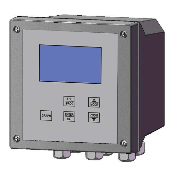
    COMMANDES, INDICATEURS ET CONNEXIONS Figure 2 – Unité murale, Panneau frontal 1. Affichage sur écran LCD 2. Touche HAUT 3. Touche ECHAP (ESC) 4. Touche ENTRÉE 5. Touche BAS 6. Touche GRAPH Figure 3 – Accès au bornier de branchement 0000137221 Rév.
  • Page 156: Ecran Graphique

    ECRAN GRAPHIQUE L’écran graphique permet une série d’affichages à travers les différents menus, pour la programmation et la visualisation durant le fonctionnement (run). 2.4.1 LISTE DES MENUS PRINCIPAUX Dans le tableau suivant, sont représentées les pages-écrans des différents menus. AFFICHAGE SUR L’ECRAN DESCRIPTION GRAPHIQUE MENU CONFIGURATIONS...
  • Page 157: Subdivision De L'ecran Graphique Par Zones En Modalite Run

    2.4.2 SUBDIVISION DE L’ECRAN GRAPHIQUE PAR ZONES EN MODALITE RUN Figure 4 – Ecran graphique – subdivision en zones Dans le tableau suivant, pour chaque zone indiquée dans la figure 4, sont brièvement représentés et décrits les symboles qui peuvent apparaître durant le fonctionnement de l’appareil de mesure. ZONE REPRESENTATION DESCRIPTION...
  • Page 158 ZONE REPRESENTATION DESCRIPTION GRAPHIQUE Permanence Sonde figée sur une valeur Set Logique Max Set logique Maxi dépassé Set Logique Min.bmp Set logique Mini dépassé Out Relay Time Temps maximum de dosage dépassé Wash Phase lavage activée Valeur sortie mA1 Valeur sortie mA2 de température mA2 auxiliaire Valeur sortie mA2 d’auxiliaire mA2 PID...
  • Page 159 ZONE REPRESENTATION DESCRIPTION GRAPHIQUE 20% de l’échelle 30% de l’échelle 40% de l’échelle 50% de l’échelle 60% de l’échelle 70% de l’échelle 80% de l’échelle 90% de l’échelle 100% de l’échelle Turbidité / solides en suspension Unité de mesure Turbidité / solides en suspension Unité...
  • Page 160: Installation

    INSTALLATION Avant d’installer l’appareil lire attentivement les indications reportées ci-après. COMPOSITION DE LA MARCHANDISE 3.1.1 INSTALLATION UNITÉ MURALE La paroi doit être bien lisse pour permettre un maintien parfait de l’unité. Figure 5 – Dimensions et encombrement de l’unité murale Dimensions mécaniques 144x144x122,5 mm Dimensions (L x H x P)
  • Page 161: Installation Unité Dans Le Tableau Électrique

    3.1.2 INSTALLATION UNITE DANS LE TABLEAU ELECTRIQUE Le mur doit être bien lisse pour permettre l'adhésion parfaite du tableau électrique où l'unité prendra place. La profondeur utile du tableau doit être de 130 mm minimum. L'épaisseur du panneau ne doit pas dépasser 5 mm. Le GABARIT de perçage doit respecter le schéma suivant : Figure 6 –...
  • Page 162: Raccordement De L'alimentation

    3.1.3 RACCORDEMENT DE L’ALIMENTATION Si possible éviter qu’à proximité de l’unité ou le long du câble se trouvent d’autres câbles destinés à la commande d’autres puissances (des perturbations de type inductif en particulier sur la partie analogique du système pourraient se créer). Appliquer une tension alternative de 100Vac à...
  • Page 163: 3.1.3.1.1 Bornier De Raccordement Pour Appareil Mural

    Figure 8 Exemples de raccordement avec les services NOTE Les schémas ci-dessus reportés sont à titre indicatif, car il manque les détails de toutes les protections et sécurités nécessaires. 3.1.3.1.1 Bornier de raccordement pour appareil mural Figure 9 Raccordements pour modèle mural N°...
  • Page 164: 3.1.3.1.2 Bornier De Raccordement Pour Appareil En Tableau

    N° BORNIER GRAPHIQUE DESCRIPTION Relais pour Valeur de consigne 1 (contact N.O.) Raccordement sonde S461 (+) Raccordement sonde S461 (-) Raccordement sonde S461 (+) Raccordement sonde S461 (-) Sortie mA2 (-) Sortie mA2 (+) Sortie mA1 (-) Sortie mA1 (+) Alimentation Sonde S75…...
  • Page 165: Branchements Au Réseau Électrique

    N° BORNIER GRAPHIQUE DESCRIPTION Alimentation (Terre) Alimentation (Phase) Alimentation (Neutre) Alimentation Sonde (+12V) Entrée digitale (-) Entrée digitale (+) RS485 (B-) RS485 (A+) Sortie mA1 (+) Sortie mA1 – mA2 (-) (commune) Sortie mA2 (+) Relais pour Lavage et Temp.(contact N.F.) Relais pour Lavage et Temp.(contact N.O.) Relais pour Alarme et Temp.(contact N.F.) Relais pour Alarme et Temp.(contact N.O.)
  • Page 166: Mode D'emploi

    MODE D’EMPLOI COMPOSITION DU SYSTEME DE MESURE 4.1.1 CONFIGURATION MINIMUM Figure 11 Configuration minimum 4.1.2 CONFIGURATION MAXIMUM Figure 12 Configuration maximum 0000137221 Rév. 3.1...
  • Page 167: Allumage Du Systeme

    ALLUMAGE DU SYSTEME Une fois que l’unité électronique et la sonde de mesure ont été installées, il est nécessaire de procéder à la programmation du logiciel qui déterminera la personnalisation des paramètres pour une utilisation correcte de l’appareil. Allumer l’appareil en l’alimentant en électricité – l’unité ne dispose pas d’interrupteur d’alimentation.
  • Page 168: Saisie Des Parametres De Travail

    Avec les touches HAUT et BAS il est possible de régler le pourcentage de contraste. 220V TURBIDITE 4263 Contrôle Contraste Ver 1.0 ATTENDRE … ENTRÉE 22.0 NTU 20.5 Figure 14 – Flèche de sélection - Fonction Contraste Ensuite avec ENTRÉE, on active l’affichage RUN. SAISIE DES PARAMETRES DE TRAVAIL Pour la saisie/modification des données de travail et pour effectuer les calibrages, l’on procède à...
  • Page 169 MENU CONFIGURATIONS (TEMPERATURE – SETUP SYSTEME) ENTRÉE (A1) (A2) 1. 0 CONFIGURATIONS 1. 0 CONFIGURATIONS 1.20 SETUP SYSTEME Température Température ENTRÉE Date/heure Système Setup Système Setup Système Communication Digital Input Digital Input Langue HAUT Setup Mesure Setup Mesure Mot de passe Ecran ENTRÉE ENTRÉE...
  • Page 170 A2) Setup Système A ce stade du programme divisé en 5 fonctions l’on configure les paramètres de base de fonctionnement de l’instrument. Description des fonctions: DATE/HEURE SYSTEME Configuration de la DATE et de l’HEURE du système qui sera mémorisée à chaque fois que les données sont mises à...
  • Page 171: Menu Configurations (Digital Input)

    4.3.1 MENU CONFIGURATIONS (DIGITAL INPUT) ENTRÉE + BAS 1. 0 CONFIGURATIONS Température Setup Système Digital input Setup Mesure ENTRÉE (B2) (B1) HAUT 1.50 DIGITAL INPUT 1.30 DIGITAL INPUT Activée Attribution Dés. SET Actif HAUT Actif B1) Digital input: Attribution Avec cette fonction il est possible d’attribuer l’entrée digitale. En configurant “Dés.
  • Page 172: Menu Sorties (Sorties Relais - Set Point 1)

    C1) Type sonde Permet de sélectionner le type de sonde utilisée, parmi sonde de turbidité et sonde de Solides en suspension. C2) Unité de mesure Permet de sélectionner l’unité de mesure parmi NTU, FTU, g/l et mg/l. En rapport avec le type de sonde reliée, certaines unités de mesure sont inhibées, cela est indiqué...
  • Page 173 Figure 15 – Fonctionnement du seuil En agissant sur les paramètres Temps ON et Temps OFF il est aussi possible de configurer un temps de RETARD ou un fonctionnement TEMPORISE du Relais 1 durant son activation. L’on peut programmer des Temps négatifs ou positifs de ON et de OFF. (fig. 13) En programmant des Temps Négatifs l’on active la fonction de RETARD: Ex.
  • Page 174: Menu Sorties (Sorties Relais - Set Point 2 Etc.)

    D2) PID-PWM En configurant le Set Point comme PID-PWM il est possible, par l’intermédiaire du Relais 1, de faire fonctionner une pompe avec commande ON/OFF comme si elle se trouvait en réglage proportionnel. Pour cette fonction la période de temps (en secondes) à l’intérieur de laquelle s’effectue ensuite le calcul du réglage PWM, doit être programmée.
  • Page 175: Set Logique

    ENTRÉE ENTRÉE ENTRÉE ENTRÉE 2.13 SET LOGIQUE 2.14 ALARME 2.15 LAVAGE 2.12 SET POINT 2 Valeur max. 20.0 NTU Active Relais Active Relais 0.0 NTU 0.0 NTU Valeur min. 0.0 NTU Désactive Set Intervalle >>> Temps ON +000 Sec Logique Relais FERME Durée >>>...
  • Page 176: Intervalle

    En configurant sur “OUVERT” il est aussi possible de contrôle les anomalies telles que le manque de tension d’alimentation et/ou de dysfonctionnement de l’instrument en question qui pourraient comporter l’ouverture immédiate du Relais. TIME OUT Avec cette fonction il est possible de configurer un temps maximum d’activation du Set Point 1 et 2 qui, une fois que celui-ci est dépassé...
  • Page 177: Menu Sorties (Set Point Temp.)

    Avec cette fonction il est possible de programmer le temps nécessaire (en secondes) pour stabiliser le lavage. 4.3.5 MENU SORTIES (SET POINT TEMP.) (F1) 2.0 SORTIE 2.1 SORTIES RELAIS ENTRÉE Set Point 1 ENTRÉE Set Point 2 Sorties Relais Set Logique Sortie analogique Alarme/Set Temp 1 Setup PID...
  • Page 178: Menu Sorties (Sortie Analogique)

    4.3.6 MENU SORTIES (SORTIE ANALOGIQUE) (G1) (G2) 2.2 SORTIE ANALOGIQUE HAUT 2.0 SORTIE 2.2 SORTIE ANALOGIQUE Mesure Mesure Sorties Relais Seconde Sortie Seconde Sortie Sortie analogique Setup PID ENTRÉE ENTRÉE ENTRÉE ENTRÉE 2.21 MESURE Range sortie 0-20 mA Limite inf. 0.0 NTU Limite sup.
  • Page 179: Menu Sorties (Setup Pid)

    G2) Seconde Sortie La seconde sortie peut être programmée comme Température ou comme COND. Si elle est programmée comme Température on doit configurer le range et les limites comme pour la sortie primaire. (voir E1). Par défaut elle est configurée: Range 0-20mA, Limite Inférieure –30°C et Limite Supérieure +140°C.
  • Page 180: Menu Calibrages

    diminue. Au contraire en programmant INVERSE lorsque la valeur mesurée augmente par rapport au seuil configuré, la valeur PID augmente. Par défaut il est configuré sur DIRECTE. PROPORTIONNEL Range Proportionnel du réglage PID par rapport au fond d’échelle de l’instrument. Ex.
  • Page 181 CALIBRAGE SONDES ANALOGIQUES (S75...) ENTRÉE 2323 mV 0mg/l 2.0 CALIBRAGES 2145 mV 10000mg/l Affichage config. 2056 mV 20000mg/l 1957 mV 30000mg/l Modification config. 1843 mV 40000mg/l Reset Default 1755 mV 50000mg/l Span 1666 mV 60000mg/l 1577 mV 70000mg/l HAUT 2323 mV 0mg/l 2.0 CALIBRAGES 2145 mV...
  • Page 182 COURBES DE CALIBRAGE “STANDARD” Ci-dessous l’on reporte les tableaux relatifs aux courbes de calibrage “standard” de chaque sonde: Sonde Mod. 7510 SAM mg/l 1524 0,01 0,00 1265 2000 2,00 0,20 1169 3000 3,00 0,30 1062 4000 4,00 0,40 5000 5,00 0,50 6000 6,00...
  • Page 183: Calibrage Manuel

    Sonde Mod. FREE Dans ce cas il est possible de réaliser une courbe de calibrage personnalisée (définie par convention “calibrage manuel”). De cette manière l’on peut faire fonctionner l’instrument avec n’importe quel type de boue ou de liquide trouble présentant des caractéristiques physiques particulières. Lorsque l’on choisit le tableau de calibrage personnalisé, l’instrument vérifie que la valeur maximum configurée dans le tableau soit inférieure au range précédemment paramétré...
  • Page 184: Procedure De Calibrage Manuel ( Exemple Sur 4 Points)

    À tout moment il est possible de rétablir la courbe de calibrage “standard” en entrant dans le sous-menu “Reset Default”. Cette opération annule de manière définitive la courbe de calibrage “manuel” éventuellement configurée. PROCEDURE DE CALIBRAGE MANUEL ( EXEMPLE SUR 4 POINTS) Pour construire une courbe de calibrage en 4 points il est nécessaire de disposer d’environ 5 litres de de boues activées et de quatre conteneurs en plastique noir.
  • Page 185: Calibrage Automatique

    3.0 CALIBRAGES Turbidité et solides en suspension Temp ENTRÉE ENTRÉE Figura 20 (J1) (J2) HAUT 3.3 CALIBRAGE TEMP 3.3 CALIBRAGE TEMP Automatique Automatique Reset Default Reset Default ENTRÉE ENTRÉE CALIBRAGE PT100 3.3 CALIBRAGE TEMP Offset de temp. Reset Default +00.0 °C Valeurs de Défaut T= +25.0 °C Le calibrage de la température permet d’aligner les valeurs lues par le capteur de température aux...
  • Page 186: Utilisation Memoire

    (K1) (K2) 4.0 ARCHIVES 4.0 ARCHIVES Affichage données Affichage données ENTRÉ Setup Setup ENTRÉ ENTRÉ 4.20 SETUP Step 1 min ENTRÉ Type archives ---> Utilisation mémoire Archives vides Reset memoire >>>> 4.10 AFFICHAGE DONNEES 4.10 AFFICHAGE DONNEES 4.10 AFFICHAGE DONNEES Première donnée >>>>...
  • Page 187: Menu Graphiques Mesures

    Elimine les données présentes en mémoire. AVERTISSEMENT Une fois cette opération effectuée, toutes les mesures archivées sont éliminées définitivement. 4.3.10 MENU GRAPHIQUES MESURES 5.0 GRAPHIQUES MESURES 20.00 Première donnée >>>> ENTRÉE ENTRÉE Date/heure >>>> Base temps 14:38 26/04/05 15:38 ENTRÉE 5.0 GRAPHIQUES MESURES Première donnée >>>>...
  • Page 188: Menu Controle Manuel

    4.3.11 MENU CONTROLE MANUEL HAUT/BAS HAUT/BAS ENTRÉ (L1) HAUT/BAS (L2) (L3) (L4) 6.0 CONTROLE MANUEL 6.0 CONTROLE MANUEL 6.0 CONTROLE MANUEL Entrées Analogiques Entrées Analogiques Entrées Analogiques Entrées Digitales Entrées Digitales Entrées Digitales Sorties analogiques Sorties Analogiques Sorties analogiques Sorties Relais Sorties Relais Sorties Relais ENTRÉ...
  • Page 189: Fonctions Run

    4.3.12 FONCTIONS RUN (N1) 16:41 ECHAP 1.0 NTU +026 (M2) HAUT EDITING RUN Set Point Set Point relais Set Point Set Point Set Point relais Set Point (M3) ENTRÉE ENTRÉE 22.0 NTU 22.0 NTU 10.0 (M4) 22.0 (M5) GRAPH TRANSFERT CLE USB GRAPH (GARDER APPUYE) ENTRÉE Dans la fenêtre en phase de mesure (RUN) il est possible d’afficher les informations suivantes:...
  • Page 190: Entretien

    M1) En appuyant sur la touche ECHAP (ESC) en phase de mesure En appuyant sur cette touche l’on entre en phase de programmation et l’on désactive toutes les fonctions de mesure et de dosage. Attention : l’instrument ne sort pas automatiquement de cette phase.
  • Page 191 MISURATORE DI TORBIDITA’, SOLIDI SOSPESI 0000137221 Rev. 3.1...
  • Page 192 INDICE 1   GENERALITÀ ................................. 5   1.1   INFORMAZIONI SUL MANUALE ......................... 5   1.1.1   CONVENZIONI ............................5   1.2   LIMITI DI UTILIZZO E PRECAUZIONI PER LA SICUREZZA ..............5   1.2.1   SICUREZZA ELETTRICA ......................... 6   1.2.2  ...
  • Page 193 4.3.12   MENU CONTROLLO MANUALE ......................46   4.3.13   FUNZIONI IN RUN ..........................47   5   MANUTENZIONE D'USO ........................... 48   5.1   AVVERTENZE PARTICOLARI PER COMPONENTI CRITICI ..............48   0000137221 Rev. 3.1...
  • Page 194: Generalità

    GENERALITÀ INFORMAZIONI SUL MANUALE Questo documento contiene informazioni di proprietà riservata. Esse possono essere soggette a modifiche ed aggiornamenti senza preavviso. Il presente manuale è parte integrante dello strumento. Al momento della prima installazione dell’apparecchio, l’operatore deve effettuare un accurato controllo del contenuto del manuale al fine di verificarne l’integrità...
  • Page 195: Sicurezza Elettrica

    ATTENZIONE Verificare prima dell’uso che tutti i requisiti di sicurezza siano soddisfatti. L’apparecchio non deve essere alimentato o connesso ad altri apparecchi fino a quando le condizioni di sicurezza non sono soddisfatte. 1.2.1 SICUREZZA ELETTRICA ATTENZIONE Tutte le connessioni presenti sulla centralina sono isolate dalla terra ambiente (massa non isolata).
  • Page 196: Simboli Grafici

    ATTENZIONE L’apparato deve essere perfettamente inserito nell’impianto. L’impianto deve essere mantenuto operativo nel pieno rispetto delle regole di sicurezza previste. I parametri impostati sulla Centralina di comando dell’analizzatore devono essere conformi ai requisiti cogenti previsti. Le segnalazioni d'avaria della centralina devono essere poste in un locale costantemente sotto controllo del personale operativo o d'assistenza dell’impianto.
  • Page 197: Simbolo Di Attenzione

    SIMBOLO DI ATTENZIONE Il simbolo mostrato di seguito, rappresenta il simbolo di ATTENZIONE e richiama l’attenzione dell’operatore alla lettura del manuale d’uso per informazioni, avvisi e suggerimenti di particolare importanza per un uso corretto e sicuro dell’apparecchio. In particolare, quando è localizzato in corrispondenza di punti di connessione a cavi e periferiche, il simbolo in oggetto rimanda ad una attenta lettura del manuale d’uso per le istruzioni riguardanti la natura di tali cavi e periferiche e le modalità...
  • Page 198: Attenzione Particolare Per Componenti Critici

    1.6.1 ATTENZIONE PARTICOLARE PER COMPONENTI CRITICI Lo strumento è provvisto di un display a cristalli liquidi LCD, che contiene piccole quantità di materiali tossici. DESCRIZIONE GENERALE L’analizzatore trattato in questo manuale è composto da Centralina Elettronica più il Manuale Tecnico La centralina, può...
  • Page 199: Principali Caratteristiche

    Tali segnali in frequenza sono assegnati a corrispondenti valori di torbidità e concentrazione solidi e vengono così visualizzati sul display. Principio di misura scattering a 90° della luce . A . C . f(α) I0 = Intensità della luce trasmessa IS = Intensità...
  • Page 200: Caratteristiche Operative

    Sonda analogica Range di misura / Unità di misura 7530 SSN 0 ÷ 1000 FTU 0 ÷ 1000 mg/L 7510 SAM 0 ÷ 12000 mg/L 0.00÷ 12.00 g/L 0.00 ÷ 1.20 % 7520 SAV 0 ÷ 70000 mg/L 0.00÷ 70.00 g/L 0.00 ÷...
  • Page 201 Allarme: Funzione Ritardo, Anomalie e Min / Max Tempo di ritardo 00:00 ÷ 99:99 min Disabilitazione Soglie Attiva / Disattiva Funzione Relè Chiuso / Aperto Campo di Permanenza 00.00 ÷ 20.00 / 000.0 ÷ 200.0 / 0 ÷ 2000Δ µS – 00.00÷20.00ΔNTU Tempo di Permanenza 00:00÷...
  • Page 202: Comandi, Indicatori E Connessioni

    COMANDI, INDICATORI E CONNESSIONI Figura 2 – Centralina da parete, Pannello frontale 1. Visualizzatore a Display LCD 2. Tasto UP 3. Tasto ESC 4. Tasto ENTER 5. Tasto DOWN 6. Tasto GRAPH Figura 3 – Accesso alla morsettiera di collegamento 0000137221 Rev.
  • Page 203: Display Grafico

    DISPLAY GRAFICO Il display grafico permette una serie di visualizzazioni per i vari menu, per la programmazione e per la visualizzazione durante il funzionamento (run). 2.4.1 ELENCO DEI MENU PRINCIPALI Nella tabella che segue sono rappresentate le videate del display che rappresentano i vari menu. VISUALIZZAZIONE DESCRIZIONE SUL DISPLAY GRAFICO...
  • Page 204: Suddivisione Del Display Grafico Per Zone In Modalita Run

    2.4.2 SUDDIVISIONE DEL DISPLAY GRAFICO PER ZONE IN MODALITA RUN Figura 4 – Display grafico - suddivisione in zone Nella tabella seguente, per ogni zona del display indicata in fig. 3, vengono rappresentati e brevemente descritti i simboli che possono apparire durante il funzionamento della Centralina di misurazione.
  • Page 205 ZONA RAPPRESENTAZIONE DESCRIZIONE GRAFICA Permanenza Sonda congelata su un valore Set Logico Max Superato Set logico Massimo Set Logico Min.bmp Superato Set logico Minimo Out Relay Time Superato tempo massimo di dosaggio Wash Fase lavaggio attiva Valore uscita mA1 Valore uscita mA2 di temperatura mA2 ausiliaria Valore uscita mA2 di ausiliaria mA2 PID...
  • Page 206 ZONA RAPPRESENTAZIONE DESCRIZIONE GRAFICA 20% della scala 30% della scala 40% della scala 50% della scala 60% della scala 70% della scala 80% della scala 90% della scala 100% della scala Torbidità / solidi sospesi Unità di misura Torbidità / solidi sospesi Unità...
  • Page 207: Installazione

    INSTALLAZIONE Prima di installare leggere con attenzione quanto sotto riportato. COMPOSIZIONE DELLA FORNITURA 3.1.1 INSTALLAZIONE CENTRALINA A PARETE La parete deve essere ben liscia per permettere la perfetta adesione della centralina. Figura 5 – Dimensioni e ingombro centralina da parete Dimensioni Meccaniche 144x144x122,5mm Dimensioni (L x H x P)
  • Page 208: Installazione Centralina Nel Quadro Elettrico

    3.1.2 INSTALLAZIONE CENTRALINA NEL QUADRO ELETTRICO La parete deve essere ben liscia per permettere la perfetta adesione del quadro elettrico dove troverà posto la centralina. La profondità utile del quadro deve essere almeno 130 mm. Lo spessore del pannello non deve superare i 5 mm. La DIMA di foratura deve rispettare il seguente schema: Figura 6 –...
  • Page 209: Collegamento Dell'alimentazione

    3.1.3 COLLEGAMENTO DELL'ALIMENTAZIONE Se possibile evitare che in prossimità della centralina o lungo il cavo di collegamento vi siano altri cavi destinati al comando di alte potenze (potrebbero crearsi disturbi di tipo induttivo specialmente sulla parte analogica del sistema). Applicare una tensione alternata da 100Vac a 240Vac-50/60Hz - o secondo i dati di targa- e il più stabilizzata possibile.
  • Page 210: 3.1.3.1.1 Morsettiera Di Collegamento Per Apparato A Parete

    Figura 8 Esempi di collegamento con le utenze NOTA Gli schemi sopra riportati sono tipicamente indicativi mancando i dettagli di tutte le protezioni e sicurezze necessarie. 3.1.3.1.1 Morsettiera di collegamento per apparato a parete Figura 9 Collegamenti per modello da parete N°...
  • Page 211: Morsettiera Di Collegamento Per Apparato A Quadro

    N° GRAFICA DESCRIZIONE MORSETTO Relè per Set Point 1 (contatto N.C.) Relè per Set Point 1 (contatto N.O.) Collegamento Sonda S461 (+) Collegamento Sonda S461 (-) Collegamento Sonda S461 (+) Collegamento Sonda S461 (-) Output mA2 (-) Output mA2 (+) Output mA1 (-) Output mA1 (+) Alimentazione Sonda S75…...
  • Page 212: Allacciamenti Alla Rete Elettrica

    N° GRAFICA DESCRIZIONE MORSETTO Alimentazione (Terra) Alimentazione (Fase) Alimentazione (Neutro) Alimentazione Sonda (+12V) Ingresso digitale (-) Ingresso digitale (+) RS485 (B-) RS485 (A+) Output mA1 (+) Output mA1 – mA2 (-) (comune) Output mA2 (+) Relè per Wash e Temp (contatto N.C.) Relè...
  • Page 213: Modalità D'uso

    MODALITÀ D’USO COMPOSIZIONE DEL SISTEMA DI MISURA 4.1.1 CONFIGURAZIONE MINIMA Figura 11 Configurazione minima 4.1.2 CONFIGURAZIONE MASSIMA Figura 12 Configurazione massima 0000137221 Rev. 3.1...
  • Page 214: Accensione Del Sistema

    ACCENSIONE DEL SISTEMA Una volta installate la centralina elettronica e la sonda di misura, occorre dedicarsi alla programmazione del software che determinerà la “personalizzazione” dei parametri per un corretto uso dell’apparecchiatura. Accendere l’apparato alimentandolo elettricamente – la centralina non dispone di un interruttore di alimentazione.
  • Page 215: Introduzione Parametri Operativi

    Tramite i tasti UP e DOWN è possibile regolare la percentuale di contrasto. 220V DOWN TURBIDITY 4263 Controllo Contrasto Ver 1.0 WAIT… ENTER 22.0 NTU 20.5 Figura 14 – Flow-Chart Funzione Contrasto Successivamente con ENTER, si attiva la visualizzazione RUN. INTRODUZIONE PARAMETRI OPERATIVI Per l’inserimento/modifica dei dati operativi e per effettuare le calibrazioni, si procede tramite i menu visualizzati sul display utilizzando i 5 tasti funzione posti sul pannello frontale della...
  • Page 216: Menu Impostazioni (Temperatura - Setup Sistema)

    4.3.1 MENU IMPOSTAZIONI (TEMPERATURA – SETUP SISTEMA) ENTER DOWN (A1) (A2) 1. 0 IMPOSTAZIONI 1. 0 IMPOSTAZIONI DOWN 1.20 SETUP SISTEMA Temperatura Temperatura ENTER Data/ora Sistema Setup Sistema Setup Sistema Comunicazione Digital Input Digital Input Lingua Setup Misura Setup Misura Password Display ENTER...
  • Page 217 A2) Setup Sistema In questo passo di programma diviso in 5 funzioni vengono impostati i parametri base di funzionamento dello strumento. Descrizione delle funzioni: DATA/ORA SISTEMA Impostazione della DATA e ORA di sistema che verrà memorizzata ogni volta che vengono storicizzati i dati.
  • Page 218: Menu Impostazioni (Digital Input)

    4.3.2 MENU IMPOSTAZIONI (DIGITAL INPUT) ENTER + DOWN 1. 0 IMPOSTAZIONI Temperatura Setup Sistema Digital input Setup Misura ENTER (B2) (B1) 1.50 DIGITAL INPUT 1.30 DIGITAL INPUT Abilitata Sì Assegnazione Dis. SET Attivo ALTO Attivo DOWN B1) Digital input: Assegnazione Mediante questa funzione è...
  • Page 219: Menu Uscite (Uscite Relay - Set Point 1)

    C1) Tipo Sonda Permette di selezionare il tipo di sonda utilizzato, tra sonda di Torbidità e sonda Solidi Sospesi. C2) Unità Misura Permette di selezionare l’unità di misura tra NTU, FTU, g/l e mg/l. In relazione al tipo di sonda collegata alcune unità...
  • Page 220 Figura 15 – Funzionamento soglia Agendo sui parametri Tempo ON e Tempo OFF inoltre è possibile impostare un tempo di RITARDO o un funzionamento TEMPORIZZATO del Relè 1 durante la sua attivazione, Si possono programmare Tempi negativi o positivi di ON e di OFF. (fig. 13) Programmando Tempi Negativi si attiva la funzione di RITARDO: Es.
  • Page 221 Impostando il Set Point come PID-PWM è possibile, tramite il Relè 1, far funzionare una pompa con comando ON/OFF quasi come fosse in regolazione proporzionale. Per questa funzione dovrà essere programmato il periodo di tempo (in secondi) all’interno del quale avverrà successivamente il calcolo della regolazione PWM.
  • Page 222: Menu Uscite (Uscite Relay - Set Point 2 Ecc.)

    4.3.5 MENU USCITE (USCITE RELAY – SET POINT 2 ECC.) 2.0 USCITA ENTER ENTER Uscite Relay B1) Set Point2 B1) Set Point2 Uscita analogica Setup PID DOWN UP/DOWN UP/DOWN (E1) UP/DOWN (E2) (E3) (E4) 2.1 USCITE RELAY 2.1 USCITE RELAY 2.1 USCITE RELAY 2.1 USCITE RELAY Set Point 1...
  • Page 223 Programmando SI, all’attivazione di qualsiasi allarme, i contatti dei Relè 1 e 2 si apriranno immediatamente e si azzereranno le uscite analogiche 1 e 2. Programmando NO, anche in caso di attivazione dell’allarme, i contatti dei Relè e le uscite analogiche non modificheranno la loro posizione.
  • Page 224: Menu Uscite (Set Point Temp.)

    Immediatamente prima dell’inizio lo strumento memorizza i valori delle misure, lo stato dei Relè 1 e 2 e i valori delle uscite analogiche e li mantiene “congelati” per tutta la durata del lavaggio. Tale situazione viene evidenziata sul display dalla presenza del simbolo della clessidra, inoltre al posto del valore di misura appare un contatore che indica quanti secondi mancano al termine della fase di lavaggio.
  • Page 225: Menu Uscite (Uscita Analogica)

    4.3.7 MENU USCITE (USCITA ANALOGICA) (G1) (G2) 2.2 USCITA ANALOGICA 2.0 USCITA 2.2 USCITA ANALOGICA Misura Misura Uscite Relay Seconda Uscita Seconda Uscita Uscita analogica Setup PID ENTER ENTER DOWN DOWN ENTER ENTER 2.21 MISURA Range uscita 0-20 mA Limite inf. 0.0 NTU Limite sup.
  • Page 226: Menu Uscite (Setup Pid)

    G2) Seconda Uscita La seconda uscita può essere programmata come Temperatura oppure COND Se viene programmata come Temperatura si dovranno impostare il range ed i limiti come per l’uscita primaria. (vedi E1). Di default viene impostato: Range 0-20mA, Limite Inferiore –30°C e Limite Superiore +140°C.
  • Page 227: Menu Calibrazioni

    PROPORZIONALE Range Proporzionale della regolazione PID rispetto al fondo scala dello strumento. Es. per la Torbidità / solidi sospesi con Range 0-20NTU, se viene programmato un Proporzionale 100% significa avere un range di ±20NTU di regolazione rispetto alla soglia impostata. Quindi il valore del proporzionale risulta inversamente proporzionale all’amplificazione di uscita, cioè...
  • Page 228 CALIBRAZIONE SONDE ANALOGICHE (S75...) ENTER 2323 mV 0mg/l 2.0 CALIBRAZIONI 2145 mV 10000mg/l Visualizzazione impostaz. 2056 mV 20000mg/l 1957 mV 30000mg/l Modifica impostaz. 1843 mV 40000mg/l Reset Default 1755 mV 50000mg/l Span 1666 mV 60000mg/l 1577 mV 70000mg/l DOWN 2323 mV 0mg/l 2.0 CALIBRAZIONI 2145 mV...
  • Page 229 CURVE DI CALIBRAZIONE “STANDARD” Di seguito sono riportate le tabelle relative alle curve di calibrazione “standard” di ciascuna sonda: Sonda Mod. 7510 SAM mg/l 1524 0,01 0,00 1265 2000 2,00 0,20 1169 3000 3,00 0,30 1062 4000 4,00 0,40 5000 5,00 0,50 6000...
  • Page 230 Sonda Mod. FREE In questo caso è possibile realizzare una curva di calibrazione personalizzata (qui definita per convenzione “calibrazione manuale”); così facendo si può far funzionare lo strumento con qualsiasi tipo di fango o liquido torbido con caratteristiche fisiche particolari Quando viene impostata la tabella di calibrazione personalizzata, lo strumento verifica che il massimo valore impostato in tabella sia inferiore al range precedentemente settato (vedasi menù...
  • Page 231 In qualsiasi momento sarà possibile ripristinare la curva di calibrazione “standard” entrando nel sub-menu “Reset Default”. Questa operazione cancellerà in modo definitivo la curva di calibrazione “manuale” eventualmente impostata. PROCEDURA DI CALIBRAZIONE MANUALE ( ESEMPIO SU 4 PUNTI ) Per costruire una curva di calibrazione di 4 punti è necessario disporre di circa 5 lt. di fango attivo e di quattro contenitori in plastica nera.
  • Page 232: Menu Archivio

    ENTER (J1) (J2) 3.3 CALIBRAZIONE TEMP 3.3 CALIBRAZIONE TEMP Automatica Automatica Reset Default Reset Default DOWN ENTER ENTER CALIBRAZIONE PT100 3.3 CALIBRAZIONE TEMP Offset di temp. Reset Default +00.0 °C Valori di Default T= +25.0 °C Sicuro? La calibrazione della temperatura permette di allineare i valori letti dal sensore di temperatura ai valori reali di analisi;...
  • Page 233 (K1) (K2) 4.0 ARCHIVIO 4.0 ARCHIVIO Visualizza dati Visualizza dati ENTER Setup Setup DOWN ENTER ENTER 4.20 SETUP Step 1 min ENTER Tipo archivio ---> Occupazione Archivio vuoto Sicuro? Reset memoria >>>> 4.10 VISUALIZZA DATI 4.10 VISUALIZZA DATI 4.10 VISUALIZZA DATI Primo dato >>>>...
  • Page 234: Menu Grafici Misure

    4.3.11 MENU GRAFICI MISURE 5.0 GRAFICI MISURE 20.00 Primo dato >>>> ENTER ENTER Data/ora >>>> Base tempi 14:38 26/04/05 15:38 DOWN ENTER 5.0 GRAFICI MISURE Primo dato >>>> Massimo 10.8 Data/ora >>>> Minimo 10.7 Base tempi Archivio vuoto Media 10.7 ENTER 5.20 DATA/ORA Visualizza...
  • Page 235: Menu Controllo Manuale

    4.3.12 MENU CONTROLLO MANUALE ENTER UP/DOWN UP/DOWN (L1) UP/DOWN (L2) (L3) (L4) 6.0 CONTROLLO MANUALE 6.0 CONTROLLO MANUALE 6.0 CONTROLLO MANUALE iIngressi Analogici iIngressi Analogici iIngressi Analogici Ingressi Digitali Ingressi Digitali Ingressi Digitali Uscite analogiche Uscite analogiche Uscite analogiche Uscite Relay Uscite Relay Uscite Relay ENTER...
  • Page 236: Funzioni In Run

    4.3.13 FUNZIONI IN RUN (N1) 16:41 1.0 NTU +026 (M2) EDITING RUN Set Point Set Point relay Set Point Set Point Set Point relay Set Point (M3) ENTER ENTER 22.0 NTU 22.0 NTU 10.0 (M4) 22.0 DOWN (M5) GRAPH PENDRIVE BACKUP GRAPH (TENERE PREMUTO) ENTER Nella schermata in fase di misura ( RUN) è...
  • Page 237: Manutenzione D'uso

    M1) Premendo il Tasto ESC in fase di misura Premendo questo tasto si entra in fase di Programmazione e si disabilitano tutte le funzioni di misura e di dosaggio. Attenzione: da questa fase lo strumento non esce automaticamente. In fase di Programmazione viene disabilitata anche la comunicazione seriale. M2) Premendo il tasto UP in fase di misura E’...

Table des Matières