Table des Matières

Publicité

Les langues disponibles

Les langues disponibles

Liens rapides

DESIGN and FLEXI LINE
Toilette Maceratrici
Macerator Toilets
Mazerationstoiletten
Sanitaires dilacérateurs
ISTRUZIONI DI INSTALLAZIONE ED USO
INSTRUCTIONS FOR INSTALLATION AND USE
AUFSTELLUNGS UND GEBRAUCHSANLEITUNG
INSTALLATION ET MODE D'EMPLOI

Publicité

Table des Matières
loading

Sommaire des Matières pour Thetford Marine TECMA Design Line

  • Page 1 DESIGN and FLEXI LINE Toilette Maceratrici Macerator Toilets Mazerationstoiletten Sanitaires dilacérateurs ISTRUZIONI DI INSTALLAZIONE ED USO INSTRUCTIONS FOR INSTALLATION AND USE AUFSTELLUNGS UND GEBRAUCHSANLEITUNG INSTALLATION ET MODE D’EMPLOI...
  • Page 2 Design and Flexi Line ISTRUZIONI DI INSTALLAZIONE ED USO | INDICE ITALIANO ........3 INSTRUCTIONS FOR INSTALLATION AND USE | ENGLISH INDEX ......38 AUFSTELLUNGS UND GEBRAUCHSANLEITUNG | DEUTSCHER INDEX ....72 INSTALLATION ET MODE D’EMPLOI | INDEX FRANÇAIS ........108 Tecma S.r.l.
  • Page 3: Table Des Matières

    Design and Flexi Line | istruzioni di installazione ed uso | ITA INDICE ITALIANO ISTRUZIONI DI INSTALLAZIONE ED USO AVVERTENZE GENERALI ALL‘UTILIZZATORE ................6 I SANITARI TECMA ......................7 Garanzia ........................7 Pulizia .......................... 8 Preparazione per l’inverno ..................8 Copriwater ........................
  • Page 4 Design and Flexi Line | istruzioni di installazione ed uso | ITA Fissaggio a terra ......................23 Elettrovalvola ......................24 Pompa di immissione ....................25 CUT-OUT Pannelli di comando .................. 25 Incasso per pannello di comando All in One ............. 25 Incasso per pannello di comando Multiframe ...........
  • Page 5 Design and Flexi Line | istruzioni di installazione ed uso | ITA A.3.3. Single System Wiring / Cablaggio Impianto Singolo ..........151 A.3.4. Multiple Single System Wiring / Cablaggio Impianto Singolo Multiplo ....151 A.3.5. Centralized Fresh Water System / Impianto Centralizzato Acqua Dolce .... 152 A.3.6.
  • Page 6: Avvertenze Generali All'utilizzatore

    Design and Flexi Line | istruzioni di installazione ed uso | ITA AVVERTENZE GENERALI ALL‘UTILIZZATORE ATTENZIONE: Assicurarsi di aver letto e compreso tutte le avvertenze riportate in questo documento prima di installare, utilizzare o intervenire sul sistema. Nel caso non si tenga conto di tali avvertenze c’è il rischio di malfunzionamento, infortunio, danni ed eventuale perdita dell’imbarcazione, folgorazione.
  • Page 7: I Sanitari Tecma

    Design and Flexi Line | istruzioni di installazione ed uso | ITA 1. I SANITARI TECMA I sanitari nautici Tecma sono made in Italy. Vengono prodotti nel distretto di Civita Castellana dove la produzione di sanitari in ceramica è rinomata per la sua eccellente qualità. Nel tempo, il dipartimento di ricerca e sviluppo dei prodotti Tecma, ha sviluppato una gamma di soluzioni con geometrie e ingombri diversificati.
  • Page 8: Pulizia

    Design and Flexi Line | istruzioni di installazione ed uso | ITA • La lista completa dei centri assistenza TECMA autorizzati è scaricabile dal ns sito www.thetfordmarine.com o può essere richiesta al ns servizio clienti ai seguenti contatti: R.O.W. (resto del mondo): info@tecma.eu / Tel. +39 0744 70 90 71- U.S.A.: 1-800- 543-1219 Pulizia La ceramica è...
  • Page 9: Funzionamento Ed Utilizzo

    Design and Flexi Line | istruzioni di installazione ed uso | ITA 2. FUNZIONAMENTO ED UTILIZZO Pannello di comando All in One Un pulsante Azionando il pulsante “FLUSH” dopo l’utilizzo, si avvierà un ciclo di lavaggio automatico al termine del quale il vaso sarà riempito con una piccola quantità d’acqua, pronta per il prossimo uso.
  • Page 10: Pannello Di Comando Multiframe

    Design and Flexi Line | istruzioni di installazione ed uso | ITA Pannello di comando Multiframe Funzionamento Azionare il pulsante “BEFORE USE” prima dell’utilizzo. Questo riempirà il vaso con una piccola quantità d’acqua. Azionare il pulsante “AFTER USE” dopo l’utilizzo, si avvierà un ciclo di lavaggio automatico al termine del quale il vaso rimarrà...
  • Page 11: Pannello Di Comando Touch Sft

    Design and Flexi Line | istruzioni di installazione ed uso | ITA Pannello di comando Touch SFT Funzionamento Il pannello Touch SFT può funzionare sia in modalità Navigazione che in modalità Ormeggio. Il ciclo della modalità Navigazione elimina completamente l’acqua all’interno del vaso alla fine dell’utilizzo impedendo la possibile fuoriuscita di acqua a seguito dei movimenti dell’imbarcazione.
  • Page 12 Design and Flexi Line | istruzioni di installazione ed uso | ITA MODALITÀ NAVIGAZIONE: la tazza rimane vuota al termine del ciclo di scarico 2. Toccare il pulsante 3. Toccare il pulsante “AFTER USE” 1. La tazza “BEFORE USE” prima di dopo aver utilizzato la toilette.
  • Page 13: Cambiare La Modalità Di Scarico

    Design and Flexi Line | istruzioni di installazione ed uso | ITA Cambiare la modalità di scarico Per impostazione predefinita, il sistema è impostato in modalità navigazione. Per passare da una modalità all’altra: 1) Premere contemporaneamente i pulsanti BEFORE USE e AFTER USE 2) Dopo 3 secondi, il LED con sensore serbatoio lampeggerà: continuare a premere 3) Dopo 5 secondi, i LED perimetrali lampeggeranno: rilasciare i pulsanti 4) La toilette automaticamente effettuerà:...
  • Page 14 Design and Flexi Line | istruzioni di installazione ed uso | ITA Fig.2: da Ormeggio a Navigazione 1. Premere contemporaneamente e MODALITÀ tenere premuti entrambi i pulsanti. ORMEGGIO 2. Dopo 3 secondi, il LED sensore serbatoio lampeggerà. Continuare a premere. 3.
  • Page 15: Led Stato Serbatoio - Funzione Blocco

    Design and Flexi Line | istruzioni di installazione ed uso | ITA LED stato serbatoio – Funzione Blocco Il pannello di comando è equipaggiato di una spia a tre colori che indica il livello di riempimento del serbatoio acque nere. Se il sensore del serbatoio rileva che il livello massimo è...
  • Page 16: Disabilitazione Per Pulizia

    Design and Flexi Line | istruzioni di installazione ed uso | ITA Disabilitazione per pulizia Per pulire il pannello Touch è possibile disabilitare temporaneamente i pulsanti. 1. Posizionare la mano davanti al pannello senza toccarlo per 15 secondi. 2. La retroilluminazione inizia a lampeggiare per 3 sec. 3.
  • Page 17: Programmazione Retroilluminazione

    Design and Flexi Line | istruzioni di installazione ed uso | ITA Programmazione retroilluminazione È possibile programmare il pannello Touch per avere la retroilluminazione: a. Sempre accesa b. Sempre spenta c. Attivata da un sensore di prossimità (default) Istruzioni per passare da un programma ad un altro: 1.
  • Page 18: Funzione Anti Tracimamento

    Design and Flexi Line | istruzioni di installazione ed uso | ITA Funzione anti tracimamento Per evitare possibili tracimamenti legati ad eccessive immissioni consecutive di acqua con il pulsante “BEFORE USE”, è inserito un blocco automatico che non consente di effettuare più...
  • Page 19 Design and Flexi Line | istruzioni di installazione ed uso | ITA ATTENZIONE: non oltrepassare il livello massimo di capienza del serbatoio quando la spia del livello serbatoio è rossa, modalità lockout. ATTENZIONE: Se la Toilette è connessa ad una presa a mare, assicurarsi che la valvola a sfera di sicurezza della presa a mare sia sempre chiusa quando ci si allontana dall’imbarcazione, anche se per un breve periodo di tempo ATTENZIONE: Per le Toilette che utilizzano sistemi ad acqua dolce che sono (anche...
  • Page 20: Installazione E Manutenzione

    Design and Flexi Line | istruzioni di installazione ed uso | ITA 3. INSTALLAZIONE E MANUTENZIONE ATTENZIONE: Assicurarsi di aver letto e compreso tutte le avvertenze riportate in questo documento prima di installare, utilizzare o intervenire sul sistema. Nel caso non si tenga conto di tali avvertenze c’è...
  • Page 21: Luogo Di Installazione

    Design and Flexi Line | istruzioni di installazione ed uso | ITA ▪ Se la Toilette è connessa ad una presa a mare, assicurarsi che ci sia una valvola di sicurezza in corrispondenza e che sia installata correttamente, devono essere di tipo marino, a sfera, azionate da una leva.
  • Page 22 Design and Flexi Line | istruzioni di installazione ed uso | ITA ▪ ci sia spazio sufficiente a passare tutte le tubazioni senza danneggiarle o piegarle in modo anomalo ▪ il paiolo dove si prevede l’istallazione sia strutturalmente idoneo a supportare il peso del vaso e di un potenziale utilizzatore, anche in navigazione dove questi carichi potrebbero essere ancora più...
  • Page 23: Fissaggio A Terra

    Design and Flexi Line | istruzioni di installazione ed uso | ITA Fissaggio a terra Il fissaggio a terra di ogni WC della linea Flexi (2G) e Design avviene tramite staffette in nylon con viti laterali e tasselli di espansione a pavimento (si esludono i modelli: Xlight che ha delle staffe in acciaio apposite ed Evolution che ha il fissaggio a parete).
  • Page 24: Elettrovalvola

    Design and Flexi Line | istruzioni di installazione ed uso | ITA Elettrovalvola Prima del montaggio eliminare lo sporco dalle tubazioni (residuo di brasatura, perle di saldatura, trucioli metallici, materiale di tenuta). Un filtro all’interno dell’elettrovalvola previene avarie causate dalle impurità dell’acqua. È raccomandato tenere il filtro dell’elettrovalvola pulito.
  • Page 25: Pompa Di Immissione

    Design and Flexi Line | istruzioni di installazione ed uso | ITA Pompa di immissione Montare la pompa di immissione in un luogo asciutto, ventilato. La pompa non può essere sommersa o esposta a spruzzi. Prevedere un adeguato fusibile nel circuito di alimentazione. La pompa può...
  • Page 26: Incasso Per Pannello Di Comando Multiframe

    Design and Flexi Line | istruzioni di installazione ed uso | ITA Incasso per pannello di comando Multiframe NOTA: La centralina Multiframe viene fornita come standard con la cornice Bticino serie Living Light. Per la compatibilità della Multiframe con le cornici commerciali fare riferimento alla seguente tabella: *Per la serie Chorus della Gewiss bisogna rimuovere le alette sul Telaio B (vedi figura) Incasso per pannello di comando Touch SFT...
  • Page 27: Sensori Di Serbatoio

    Design and Flexi Line | istruzioni di installazione ed uso | ITA Sensori di serbatoio Il cablaggio sensori delle centraline, sia nella versione standard a un livello (grigio/nero), che nella versione a due livelli (rosso/nero e bianco/verde) hanno una tensione di 7V. Si possono collegare: •...
  • Page 28: Attrezzatura Necessaria

    Design and Flexi Line | istruzioni di installazione ed uso | ITA Per l’installazione, pulire la superficie del lato alto del serbatoio in alto - circa sulla mezzeria con alcool isopropilico (non fornito) dove verrà montato il sensore. Una volta ben pulita e asciutta, posizionare il sensore facendo pressione sul punto individuato.
  • Page 29 Design and Flexi Line | istruzioni di installazione ed uso | ITA Fig. 1 ATTENZIONE: La linea di galleggiamento presa in esame dovrà essere calcolata tenendo in considerazione i vari assetti durante la navigazione. Vedi esempio fig.2. Fig. 2 ATTENZIONE: Seguire le normative vigenti per la progettazione e la realizzazione degli impianti di acque nere e per le procedure di scarico.
  • Page 30: Impianto Centralizzato - Acqua Dolce

    Design and Flexi Line | istruzioni di installazione ed uso | ITA Impianto Centralizzato - Acqua Dolce Impianto idraulico 3.8.1.1 Il ciclo di scarico dei wc nautico TECMA utilizza l’acqua dolce del serbatoio. Per ogni wc, l’elettrovalvola può essere integrata nel vaso, direttamente collegata all’inlet/nozzle attraverso il tubo di gomma nero in dotazione, oppure montata nell’impianto di acqua dolce di bordo (lo stesso che serve lavandini, docce e altre utenze).
  • Page 31: Impianto Singolo E Multiplo - Acqua Salata

    Design and Flexi Line | istruzioni di installazione ed uso | ITA Impianto elettrico 110V/230V 3.8.1.3 I prodotti Tecma con motore 110V/230V vengono predisposti con una spina da collegare all’alimentazione. Schemi in sezione A.3.6.5/6 Spina Alimentazione generale (motore/elettrovalvola) – Spina Shuko CEE/USCan Nero/Marrone trasformatore / centralina Nero/Blu...
  • Page 32: Impianto Elettrico

    Design and Flexi Line | istruzioni di installazione ed uso | ITA Impianto elettrico 3.8.2.2 Schema in sezione A.3.3/4. Ogni centralina viene cablata connettendo Nero/Marrone Motore vaso Nero/Blu Pompa di immissione Nero/Grigio Sensore serbatoio Nero/Rosso Alimentazione (con fusibile sul rosso) Il tasto “BEFORE USE”...
  • Page 33 Design and Flexi Line | istruzioni di installazione ed uso | ITA Corpo Placca di miscelatore installazione Flangia OD 60mm / ID 42mm Flangia OD 60mm / ID 42mm 42mm OD 55mm lenght Acqua miscelata diretta all’ugello Ferramenta e guarnizioni Maniglia Standard Ingressi acqua 3/8”...
  • Page 34 Design and Flexi Line | istruzioni di installazione ed uso | ITA Opzione 1*: Miscelatore e maniglia bidet integrati nella toilet Ugello Bidet Ingressi acqua calda/fredda -> Connettore femmina filettato da 3/8” Opzione 2*: Miscelatore e maniglia bidet integrati nella toilet (Toilet “Privilege, Evolution”) Ugello ingresso acqua 3/8”...
  • Page 35: Risoluzione Dei Problemi

    Design and Flexi Line | istruzioni di installazione ed uso | ITA Dettaglio miscelatare e maniglia (standard) bidet a parete (Privilege/ Evolution): Miscelatore OD 42 mm Lunghezza 55 mm (parte cromata) Qualsiasi altra maniglia e miscelatore in commercio in alternativa può essere utilizzato per miscelare l'acqua.
  • Page 36: Si Possono Utilizzare Prodotti Acidi O Aggressivi

    Design and Flexi Line | istruzioni di installazione ed uso | ITA  Effettuare dei cicli di risciacquo con acqua pulita.  Svuotare completamente tutti gli impianti in modo da non avere problemi di gelo all’interno delle tubature.  In generale, effettuare periodica manutenzione dei filtri dell’elettrovalvola e/o della pompa di immissione.
  • Page 37: Devo Installare Una Condotta Di Ventilazione Per La Valvola Di Ventilazione Integrata

    Design and Flexi Line | istruzioni di installazione ed uso | ITA Devo installare una condotta di ventilazione per la valvola di ventilazione integrata? Non è necessario effettuare la canalizzazione della valvola di ventilazione integrata nel manicotto scarico della toilette. E’...
  • Page 38 Design and Flexi Line | instructions for installation and use | ENG ENGLISH INDEX INSTRUCTIONS FOR INSTALLATION AND USE GENERAL WARNINGS TO THE USER ..................41 TECMA SANITARY SYSTEM....................42 Warranty ........................42 Cleaning ........................43 Winterising ........................ 43 Toilet seat cover ......................43 Choosing the type of toilet paper ................
  • Page 39 Design and Flexi Line | instructions for installation and use | ENG Floor fixation ......................58 Solenoid valve ......................59 Inlet pump ......................... 60 CUT-OUT control panels .................... 60 Cut out for All-in-One control panel: ..............60 Cut out for Multiframe control panel: ............... 61 Cut out for Touch SFT control panel: ..............
  • Page 40 Design and Flexi Line | instructions for installation and use | ENG A.3.4. Multiple Single System Wiring / Cablaggio Impianto Singolo Multiplo ....151 A.3.5. Centralized Fresh Water System / Impianto Centralizzato Acqua Dolce .... 152 A.3.6. Centralized Fresh Water Wiring / Cablaggio Centralizzato Acqua Dolce .... 153 12 V/24 V with All In One Switch ..............
  • Page 41: General Warnings To The User

    Design and Flexi Line | instructions for installation and use | ENG GENERAL WARNINGS TO THE USER WARNING: Read and understand the warnings listed in this document before installing, using, or servicing the system. Failure to comply with these warnings may cause malfunctions, injuries, damage, loss of the property, and electrocution.
  • Page 42: Tecma Sanitary System

    Design and Flexi Line | instructions for installation and use | ENG 1. TECMA SANITARY SYSTEM Tecma marine sanitary systems are made in Italy. The entire production is made in the district of Civita Castellana, which is well known for manufacturing top-quality ceramic sanitary ware.
  • Page 43: Cleaning

    Design and Flexi Line | instructions for installation and use | ENG Cleaning Ceramic is particularly suitable for toilets, as it guarantees hygiene and it is resistant against any cleaning product. Do not use acetone- or trichlorethylene-based products, or any product that may irreversibly damage the rubber components of the pump/macerator/check valves.
  • Page 44: Operating The System

    Design and Flexi Line | instructions for installation and use | ENG 2. OPERATING THE SYSTEM All-in-one control panel One button Press the “FLUSH” button to start the automatic flush cycle, after which the toilet will be refilled with a small amount of water, ready for the next use. FLUSH TANK LEVEL Two buttons...
  • Page 45: Multiframe Control Panel

    Design and Flexi Line | instructions for installation and use | ENG Multiframe control panel Function Press the “BEFORE USE” button before using the toilet. This will fill the toilet with a small amount of water. Press the “AFTER USE” button after using the toilet. This will start the automatic flush cycle, which will empty the toilet.
  • Page 46: Touch Sft Control Panel

    Design and Flexi Line | instructions for installation and use | ENG Touch SFT control panel Function The Touch SFT control panel can work both in Navigation mode and in Mooring mode. The Navigation mode cycle eliminates the water inside the bowl at the end of use, preventing the possible leakage of water due to the movements of the boat.
  • Page 47 Design and Flexi Line | instructions for installation and use | ENG SAILING MODE: the toilet bowl remains empty at the end of the flush cycle 2. Press the “BEFORE USE” 3. Press the “AFTER USE” button after 1. The bowl button before using the toilet.
  • Page 48: Changing Flushing Mode

    Design and Flexi Line | instructions for installation and use | ENG Changing flushing mode The system is set on sailing mode by default. To switch from one mode to another: 1) Press and hold the BEFORE USE and AFTER USE buttons simultaneously 2) After 3 seconds, the sensor LED will flash: keep pressing.
  • Page 49 Design and Flexi Line | instructions for installation and use | ENG Fig.2: from Mooring to Sailing 1. Press and hold the BEFORE USE MOORING and AFTER USE buttons MODE simultaneously 2. After 3 seconds, the sensor LED will flash. Hold down.
  • Page 50: Tank Level Led - Block Function

    Design and Flexi Line | instructions for installation and use | ENG Tank level LED – Block function The control panel is equipped with a 3-colour LED, which indicates the blackwater tank level. As soon as the maximum level is reached, the sensor disables the inlet of water inside the bowl.
  • Page 51: Disabling The Toilet For Cleaning Operations

    Design and Flexi Line | instructions for installation and use | ENG Disabling the toilet for cleaning operations. Temporarily disable the buttons in order to clean the Touch control panel. 1. Place your hand on the panel for 15 seconds without touch it. 2.
  • Page 52: Programming The Backlight

    Design and Flexi Line | instructions for installation and use | ENG Programming the backlight You can program the Touch panel to have the backlight: a. Always on b. Always off c. Activated with a proximity sensor (default) Instructions to switch from one program to another: 1.
  • Page 53: Anti Overflow Function

    Design and Flexi Line | instructions for installation and use | ENG Anti overflow function To avoid possible overflows related to excessive consecutive inlet of water with the "BEFORE USE" button, an automatic block is enabled which does not allow more than two consecutive inlets.
  • Page 54 Design and Flexi Line | instructions for installation and use | ENG WARNING: do not to exceed the tank maximum level when the “Tank Level” LED is red (lockout mode). WARNING: If the toilet is connected to a seacock, make sure that its safety ball valve is always closed when the boat is unattended, even for a short time.
  • Page 55: Installation And Service

    Design and Flexi Line | instructions for installation and use | ENG 3. INSTALLATION AND SERVICE WARNING: Read and understand the warnings listed in this document before installing, using, or servicing the system. Failure to comply with these warnings may cause injuries, damage, loss of the property, and electrocution.
  • Page 56: Installation Site

    Design and Flexi Line | instructions for installation and use | ENG ▪ Only use stainless steel hardware. Always use the supplied ceramic-protection rubber inserts. Any toilet assembly errors may result in improper movements, which may damage objects or injure persons. ▪...
  • Page 57 Design and Flexi Line | instructions for installation and use | ENG described in section 3.8 "System" The Flexi 2G and Design line integrates an air admittance valve already in the discharge internal hose. ▪ In the case of non-centralized systems (sea water) with toilet installed below the waterline, make sure the space to install the safety valve ventilation necessary authorization and discharge at a sufficiently higher proportion to it.
  • Page 58: Floor Fixation

    Design and Flexi Line | instructions for installation and use | ENG Floor fixation The floor fixation of each head of Flexi Line and Design is using nylon brackets with side screws and floor anchors (excluding Xlight and Evolution with special mounting kit). Each toilet is provided with a template with the measures for drilling to the floor.
  • Page 59: Solenoid Valve

    Design and Flexi Line | instructions for installation and use | ENG Solenoid valve Before installing the solenoid valve, clean the pipes (brazing or welding residues, metal chips, seal material). A filter inside the solenoid valve prevents failures resulting from water impurities.
  • Page 60: Inlet Pump

    Design and Flexi Line | instructions for installation and use | ENG Inlet pump Install the inlet pump in a dry, ventilated place. The pump can’t be submerged or exposed to sprays. Install a fuse in the power supply circuit. The pump can be assembled horizontally as well as vertically (in this case, the pumping unit must face downwards).
  • Page 61: Cut Out For Multiframe Control Panel

    Design and Flexi Line | instructions for installation and use | ENG Cut out for Multiframe control panel: NOTE: The Multiframe control unit is supplied as standard with the Bticino Living Light series frame. For compatibility of Multiframe with commercial frames, refer to the following table: *To install the Chorus line (Gewiss) remove the fins from the Frame B (see the picture) Cut out for Touch SFT control panel:...
  • Page 62: Tank Sensors

    Design and Flexi Line | instructions for installation and use | ENG Tank sensors The sensor wiring of the control units, both in the standard one-level version (grey / black), and in the two-level version for Touch (red / black and white / green) have a voltage of 7V. You can connect: •...
  • Page 63: Equipment Required

    Design and Flexi Line | instructions for installation and use | ENG Use isopropyl alcohol (not included) to clean the side of the tank at the top - approximately on the left-right centreline where the sensor will be mounted. When thoroughly clean and dry, firmly press the sensor into place.
  • Page 64 Design and Flexi Line | instructions for installation and use | ENG Fig. 1 WARNING: The floating line must be calculated taking into consideration the various sailing trims. See fig. 2. Fig. 2 WARNING: Comply with the standards in force when designing and installing the blackwater systems and during the flushing procedures.
  • Page 65: Centralised System - Fresh Water

    Design and Flexi Line | instructions for installation and use | ENG Centralised System - Fresh Water Hydraulic system 3.8.1.1 The TECMA's toilet flushing cycles use the tank fresh water. The solenoid valve can be integrated in the toilet, directly connected to the inlet/nozzle via the supplied black rubber pipe.
  • Page 66: Single And Multiple System - Salt Water

    Design and Flexi Line | instructions for installation and use | ENG 110V/230V Electrical system 3.8.1.3 Tecma products with a 110V/230V motor have a plug, which must be connected to the power supply. Diagrams in section A.3.6.5/6. Plug Main power supply (motor and solenoid valve) - Shuko CEE/ US-Can Black/Brown transformer/control unit Black/Blue...
  • Page 67: Electrical System

    Design and Flexi Line | instructions for installation and use | ENG Electrical system 3.8.2.2 Diagram in section A.3.3/4. Every control unit is wired by connecting Black/brown toilet motor Black/Blue Inlet pump Black/Grey Tank sensor Black/Red Power supply (with fuse on the red wire) The «...
  • Page 68 Design and Flexi Line | instructions for installation and use | ENG Mixer body 42mm OD 55mm lenght Flange OD 60mm / ID 42mm Mounting bracket Mixed water to toilet nozzle Hot or cold-water supply Standard 3/8” connection (threaded Hardware + Handle female) gaskets...
  • Page 69 Design and Flexi Line | instructions for installation and use | ENG Option 1: Mixer and handle integrated to the ceramic toilet * Water inlet nozzle Hot or cold-water supply 3/8” connection (threaded female) Option 2: Mixer and handle wall mounted (Privilege / Evolution) * Water inlet nozzle 600mm length hose...
  • Page 70: Troubleshooting

    Design and Flexi Line | instructions for installation and use | ENG Mixer OD 42 mm Length 55 mm (chromed part) Any other commercial handle/mixer can alternatively be used to mix the water The customer is free to select a wall mounted mixer from the same collection of the bathroom and use it to control the bidet integrated in the toilet.
  • Page 71: Is It Possible To Use Acid Or Aggressive Products

    Design and Flexi Line | instructions for installation and use | ENG Comply with the environmental protection standards in force when choosing and using these products. We recommend cleaning the tanks and pipes with Thetford Tank Freshener. Is it possible to use acid or aggressive products? Plastic components of the TECMA toilet have been tested with several marketed cleaning products.
  • Page 72 Design and Flexi Line | aufstellungs und gebrauchsanleitung | DEU DEUTSCHER INDEX AUFSTELLUNGS UND GEBRAUCHSANLEITUNG WARNUNGEN FÜR DEN BENUTZER ..................75 TECMA-SANITÄRANLAGEN ....................76 Garantie ........................76 Reinigung ........................77 Vorbereitung zum Winter ..................77 Toilettendeckel ......................77 Wahl des Toilettenpapiers ..................78 FUNKTION UND VERWENDUNG ..................
  • Page 73 Design and Flexi Line | aufstellungs und gebrauchsanleitung | DEU Bodenbefestigung ..................... 92 Magnetventil ......................93 Einlasspumpe ......................94 AUSSPARUNGEN für die Bedientafeln ..............94 Aussparung für Bedientafel All in One: .............. 94 Aussparung für Bedientafel Multiframe ............95 Aussparung für Bedientafel Touch SFT .............. 95 Tanksensoren ......................
  • Page 74 Design and Flexi Line | aufstellungs und gebrauchsanleitung | DEU A.3.3. Single System Wiring / Cablaggio Impianto Singolo ..........151 A.3.4. Multiple Single System Wiring / Cablaggio Impianto Singolo Multiplo ....151 A.3.5. Centralized Fresh Water System / Impianto Centralizzato Acqua Dolce .... 152 A.3.6.
  • Page 75: Warnungen Für Den Benutzer

    Design and Flexi Line | aufstellungs und gebrauchsanleitung | DEU WARNUNGEN FÜR DEN BENUTZER WARNUNG: Stellen Sie sicher, dass Sie alle im vorliegenden Dokument enthaltenen Warnhinweise gelesen und verstanden haben, bevor Sie das System installieren, verwenden oder Eingriffe daran vornehmen. Sollten diese Warnungen nicht befolgt werden, kann dies zu Funktionsstörungen, Verletzungen, Beschädigungen, dem eventuellen Verlust des Bootes oder Stromschlägen führen.
  • Page 76: Tecma-Sanitäranlagen

    Design and Flexi Line | aufstellungs und gebrauchsanleitung | DEU 1. TECMA-SANITÄRANLAGEN Die TECMA-Sanitäranlagen für die Schifffahrt sind Made in Italy. Ihre Produktion erfolgt in Civita Castellana, wo die Produktion von Sanitäranlagen aus Keramik dank ihrer hervorragenden Qualität berühmt ist. Im Laufe der Zeit hat die Forschungs- und Entwicklungsabteilung von TECMA eine Produktpalette mit unterschiedlichen Formen und Abmessungen entwickelt.
  • Page 77: Reinigung

    Design and Flexi Line | aufstellungs und gebrauchsanleitung | DEU b) Kurze Beschreibung des Schadens / des aufgetretenen Problems • Eine vollständige Liste der autorisierten Kundendienststellen von TECMA steht auf www.thetfordmarine.com zum Download zur Verfügung oder kann bei unserem Kundendienst unter folgenden Nummern angefordert werden: REST DER WELT: info@tecma.eu / Tel.
  • Page 78: Wahl Des Toilettenpapiers

    Design and Flexi Line | aufstellungs und gebrauchsanleitung | DEU Wahl des Toilettenpapiers Verwenden Sie ausschließlich Toilettenpapier. Das System wurde für die wirksame Entsorgung von Toilettenpapier entwickelt. Benutzen Sie keine Papiertücher oder andere Papierarten. TECMA empfiehlt die Verwendung von Thetford Aqua-Soft. 2.
  • Page 79: Bedientafel Multiframe

    Design and Flexi Line | aufstellungs und gebrauchsanleitung | DEU Bedientafel Multiframe Betrieb Vor Benutzung der Toilette die Taste "BEFORE USE" drücken. Dadurch wird die Toilette mit einer geringen Wassermenge gefüllt. Nach Benutzung der Toilette die Taste "AFTER USE" drücken, wodurch automatisch ein Spülzyklus gestartet wird. Am Ende des Zyklus bleibt die Toilette leer.
  • Page 80: Bedientafeln Touch Sft

    Design and Flexi Line | aufstellungs und gebrauchsanleitung | DEU Bedientafeln Touch SFT Betrieb Das Touch SFT-Bedienfeld kann sowohl im Navigationsmodus als auch im Mooring-Modus verwendet werden. Im Navigationsmodus wird das Wasser am Ende der Nutzung vollständig aus dem Schiff entfernt, wodurch ein mögliches Auslaufen von Wasser infolge der Bewegungen des Bootes verhindert wird.
  • Page 81 Design and Flexi Line | aufstellungs und gebrauchsanleitung | DEU NAVIGATIONSMODUS: die Toilette bleibt am Ende des Spülzyklus leer 2. Vor Benutzung der Toilette 3. Nach Benutzung der Toilette die Taste 1. Die die Taste "BEFORE USE" „AFTER USE“ drücken. Toilette ist Durch eine kombinierte Aktion von drücken.
  • Page 82: Änderung Des Spülmodus

    Design and Flexi Line | aufstellungs und gebrauchsanleitung | DEU Änderung des Spülmodus Standardmäßig ist das System auf den Navigationsmodus eingestellt. So wechseln Sie von einem Modus in einen anderen: 1) Drücken Sie gleichzeitig die Tasten BEFORE USE und AFTER USE 2) Nach 3 Sekunden blinkt die Tanksensor-LED: Drücken Sie weiter 3) Nach 5 Sekunden blinken die Perimeter-LEDs: Lassen Sie die Tasten los 4) Die Toilette führt automatisch aus:...
  • Page 83 Design and Flexi Line | aufstellungs und gebrauchsanleitung | DEU Abb.2: vom Hafenmodus zum Navigationsmodus 1. Halten Sie beide Tasten HAFENMODUS gleichzeitig gedrückt. 2. Nach 3 Sekunden blinkt die Tanksensor-LED. Drücken Sie weiter. 3. Nach 5 Sekunden blinken die Perimeter-LEDs. Lassen Sie die Tasten los.
  • Page 84: Tankstatus-Led - Sperrfunktion

    Design and Flexi Line | aufstellungs und gebrauchsanleitung | DEU Tankstatus-LED - Sperrfunktion Das Bedienfeld ist mit einer dreifarbigen Warnleuchte ausgestattet, die den Füllstand des Schwarzwassertanks anzeigt. Wenn der Tankfühler feststellt, dass der maximale Füllstand erreicht wurde, verhindert die Sperrfunktion, dass weiteres Wasser in die Toilette gelangt. Nur die Aktivierung der Mazerierpumpe bleibt aktiv.
  • Page 85: Deaktivierung Für Die Reinigung

    Design and Flexi Line | aufstellungs und gebrauchsanleitung | DEU Deaktivierung für die Reinigung Für die Reinigung der Bedientafel Touch können die Tasten vorübergehend deaktiviert werden. 1. Legen Sie Ihre Hand vor das Bedienfeld, ohne es 15 Sekunden lang zu berühren. 2.
  • Page 86: Programmierung Der Hintergrundbeleuchtung

    Design and Flexi Line | aufstellungs und gebrauchsanleitung | DEU Programmierung der Hintergrundbeleuchtung Für die Bedientafel Touch kann eine Hintergrundbeleuchtung programmiert werden. a. Immer aktiviert b. Immer deaktiviert c. Über einen Näherungssensor aktiviert (Standard) Anleitung für den Übergang von einem Programm zu einem anderen: 1.
  • Page 87: Überlaufsicherung

    Design and Flexi Line | aufstellungs und gebrauchsanleitung | DEU Überlaufsicherung Um mögliche Überläufe durch übermäßige aufeinanderfolgende Eingaben von Wasser mit der Schaltfläche "BEFORE USE" zu vermeiden, wird eine automatische Sperre eingefügt, die nicht mehr als zwei aufeinanderfolgende Eingaben zulässt. Die Sperre wird beim nächsten Einschalten der Mazerierpumpe deaktiviert.
  • Page 88 Design and Flexi Line | aufstellungs und gebrauchsanleitung | DEU ACHTUNG: Darauf achten, dass das maximale Fassungsvermögen des Tanks nicht überschritten wird, wenn Tank Level LED rot leuchtet, Sperrmodus. ACHTUNG: Wenn die Toilette mit einem Seeventil verbunden ist, muss sichergestellt werden, dass das Sicherheits-Kugelventil des Seeventils immer geschlossen ist, wenn das Boot - auch nur für kurze Zeit - verlassen wird.
  • Page 89: Installation Und Wartung

    Design and Flexi Line | aufstellungs und gebrauchsanleitung | DEU 3. INSTALLATION UND WARTUNG ACHTUNG: Stellen Sie sicher, dass Sie alle im vorliegenden Dokument enthaltenen Warnhinweise gelesen und verstanden haben, bevor Sie das System installieren, verwenden oder Eingriffe daran vornehmen. Sollten diese Warnungen nicht befolgt werden, kann dies zu Verletzungen, Beschädigungen, dem eventuellen Verlust des Bootes oder Stromschlägen führen.
  • Page 90: Einbauort

    Design and Flexi Line | aufstellungs und gebrauchsanleitung | DEU sein, und sämtliche Anschlüsse müssen mit zwei (2) Schellen aus rostfreiem Stahl gesichert werden. Der feste Sitz dieser Schellen muss regelmäßig kontrolliert werden, um eventuellen Leckagen vorzubeugen. ▪ Wenn die Toilette an ein Seeventil angeschlossen ist, muss sichergestellt werden, dass ein entsprechendes Sicherheitsventil vorhanden ist, und dass es korrekt installiert ist.
  • Page 91 Design and Flexi Line | aufstellungs und gebrauchsanleitung | DEU ▪ Es muss genügend Raum für die Durchführung aller Leitungen vorhanden sein, ohne sie zu beschädigen oder zu knicken. ▪ Der für die Installation vorgesehene Fußboden muss ausreichend stabil sein, um das Gewicht der Toilette und des Benutzers zu tragen.
  • Page 92: Bodenbefestigung

    Design and Flexi Line | aufstellungs und gebrauchsanleitung | DEU ▪ Die Installation des Modells EVOLUTION erfordert eine vertikale Befestigungsplatte (nicht Lieferumfang enthalten) oder vernünftig die Last an der Spritzwand zu zu sichern. Bodenbefestigung Die Bodenbefestigung jeder Toilette von Flexi-Linie 2G und Design ist über Nylon Klammern mit seitlichen Schrauben und Bodenanker (ohne „Xlight“...
  • Page 93: Magnetventil

    Design and Flexi Line | aufstellungs und gebrauchsanleitung | DEU Magnetventil Vor der Montage müssen sämtliche Verunreinigungen von den Leitungen entfernt werden (Löt- und Schweißrückstände, Metallspäne, Dichtungsmaterial). Ein Filter im Inneren des Magnetventils dient zur Vorbeugung von Störungen durch verunreinigtes Wasser. Es wird empfohlen, den Filter des Magnetventils immer sauber zu halten.
  • Page 94: Einlasspumpe

    Design and Flexi Line | aufstellungs und gebrauchsanleitung | DEU Einlasspumpe Die Einlasspumpe an einem trockenen und belüfteten Ort installieren. Die Pumpe darf nicht unter Wasser liegen oder Wasserspritzern ausgesetzt sein. Im Versorgungskreis muss eine geeignete Sicherung vorgesehen werden. Die Pumpe kann sowohl horizontal als auch vertikal installiert werden (bei vertikaler Installation muss die Pumpeinheit nach unten ausgerichtet werden).
  • Page 95: Aussparung Für Bedientafel Multiframe

    Design and Flexi Line | aufstellungs und gebrauchsanleitung | DEU Aussparung für Bedientafel Multiframe ANMERKUNG: Die Multiframe-Steuereinheit wird standardmäßig mit dem Rahmen der Bticino Living Light-Serie geliefert. Informationen zur Kompatibilität von Multiframe mit kommerziellen Frames finden Sie in der folgenden Tabelle: *Für die Gewiss-Chorus-Serie müssen die Klappen am Rahmen B entfernt werden (siehe Abbildung).
  • Page 96: Tanksensoren

    Design and Flexi Line | aufstellungs und gebrauchsanleitung | DEU Tanksensoren Die Sensorverdrahtung der Steuergeräte hat sowohl in der Standardversion mit einer Ebene (grau / schwarz) als auch in der Version mit zwei Ebenen für die Touch (rot / schwarz und weiß...
  • Page 97: Erforderliches Werkzeug

    Design and Flexi Line | aufstellungs und gebrauchsanleitung | DEU Für die Installation, die Oberfläche auf der Tankoberseite, wo der Sensor montiert werden soll - ungefähr auf der von links nach rechts führenden Mittellinie - mit Isopropylalkohol (nicht im Lieferumfang enthalten) reinigen. Nachdem die Oberfläche sorgfältig gereinigt und getrocknet wurde, den Sensor fest andrücken.
  • Page 98 Design and Flexi Line | aufstellungs und gebrauchsanleitung | DEU Abb. 1 ACHTUNG: Bei der Berechnung der in Erwägung gezogenen Wasserlinie müssen die verschiedenen Schwimmlagen während der Navigation berücksichtigt werden. Siehe Beispiel Abb. 2 Abb. 2 ACHTUNG: Bei der Planung und Herstellung der Schmutzwasseranlagen und den Auslassvorgängen sind die geltenden Normen zu berücksichtigen.
  • Page 99: Zentralisierte Anlage - Süsswasser

    Design and Flexi Line | aufstellungs und gebrauchsanleitung | DEU Zentralisierte Anlage - Süsswasser Hydraulikanlage 3.8.1.1 Für den Spülzyklus der TECMA-Toiletten für die Schifffahrt wird Süßwasser aus dem Tank verwendet. Bei jeder Toilette kann das Magnetventil in die Toilettenschüssel eingebaut, direkt an den Einlauf/die Düse über den mitgelieferten schwarzen Gummischlauch angeschlossen oder in der Süßwasseranlage an Bord (die auch für Waschbecken, Duschen und andere Abnehmer verwendet wird) montiert werden.
  • Page 100 Design and Flexi Line | aufstellungs und gebrauchsanleitung | DEU Elektroanlage 12V/24V 3.8.1.2 Schemen in den Abschnitten A.3.6.1/2/3/4. Bei der Verkabelung jeder Steuereinheit werden folgende Anschlüsse vorgenommen: Schwarz/Braun Toilettenmotor Schwarz/Blau Magnetventil Schwarz/Grau Tanksensor Schwarz/Rot Versorgung (mit Sicherung auf Positiv) Unabhängig von der Anlage der Sanitäreinrichtungen steht der Autoklav immer unter Spannung.
  • Page 101: Einzel- Und Mehrfachanlage - Salzwasser

    Design and Flexi Line | aufstellungs und gebrauchsanleitung | DEU Einzel- Und Mehrfachanlage – Salzwasser Hydraulikanlage 3.8.2.1 Für die Spülzyklen der TECMA-Toiletten für die Schifffahrt wird Wasser verwendet, das von außen über ein Seeventil aufgenommen wird. Schemen in den Abschnitten A.3.1/2. Wenn ein Spülzyklus aktiviert wird, sorgt die Bedientafel für die Aktivierung einer speziellen Einlasspumpe, die das Wasser über eine entsprechende Anlage befördert.
  • Page 102: Option Mit Integrierte Bidet

    Design and Flexi Line | aufstellungs und gebrauchsanleitung | DEU Option mit Integrierte Bidet Die integrierte Bidet-Option bietet die Möglichkeit für die Verwendung der Toilette im dual- Modus: Toilette und Bidet. Die spezielle Düse kombiniert frisches Wasser für die Toilettenspülung und Bidet-wasser das gemischt und kontrolliert mit einem eleganten Griff wird.
  • Page 103 Design and Flexi Line | aufstellungs und gebrauchsanleitung | DEU Mischwasser zu WC-Duese Montagehalterung Flange OD 60mm / ID 42mm Wassermischer- Koerper 42mm OD 55mm lenght Standard Hardware Griff Warm/kalt wasseranschluss 3/8 " Innengewinde Duese Die Duese ist installiert direkt auf der Toilette. Schließen Sie die Schläuche und die Installation ist abgeschlossen.
  • Page 104 Design and Flexi Line | aufstellungs und gebrauchsanleitung | DEU Option 1: Wassermischere und Griff integrierte in der Toilette * Wassereinlass Duese Warm/kalt wasseranschluss 3/8 " Innengewinde Option 2: Wassermischere und Griff an der Wand * Wassereinlass Duese Warm/kalt wasseranschluss 3/8 " Innengewinde 600mm Laenge hose...
  • Page 105: Fehlerbehebung

    Design and Flexi Line | aufstellungs und gebrauchsanleitung | DEU Wand-Wassermischer Details (Privilege- Evolution): Wassermischer OD 42 mm Laenge 55 mm (crome) Jeder andere kommerzielle Wassermischere mit Griff kann auch alternativ verwendet werden, um das Wasser zu mischen. Der Kunde steht es frei z.b. aus der gleichen Kollektion der Wasserhähne des Badezimmers, zu waehlen, um das Bidet –funktion in der Toilette zu steuern.
  • Page 106: Häufig Gestellte Fragen

    Design and Flexi Line | aufstellungs und gebrauchsanleitung | DEU 5. HÄUFIG GESTELLTE FRAGEN Können mehrere Toiletten an die gleiche Leitung angeschlossen werden. Ja. In diesem Fall müssen Y-Verbindungen anstelle der T-Verbindungen verwendet werden. Es müssen immer Belüftungsventile vorgesehen werden. Setzen Sie eine geeignete Leitung laut der Anzahl der Toiletten.
  • Page 107: Soll Man Ein Lüftungskanal Für Das Integrierte Lüftungsventil Installieren

    Design and Flexi Line | aufstellungs und gebrauchsanleitung | DEU Für zentralisierte Systeme mit einer sehr langer Abflussleitung und einem Risiko von „Syphoning“-Effekt, ein belüfteter Siphon wird immer empfohlen. Der Flexi 2G und Design Line ist mit einem Innenrohr mit integriertem Belüftungsventil ausgestattet, die in den meisten Fällen, den Siphon hinter der Trennwand ersetzt.
  • Page 108 Design and Flexi Line | installation et mode d’emploi | FRA INDEX FRANCAIS INSTALLATION ET MODE D’EMPLOI AVERTISSEMENTS GENERAL DE L'UTILISATEUR ..............111 LES TOILETTES TECMA ....................112 Garantie ........................112 Nettoyage ........................ 113 Préparation pour l’hiver ..................113 Couvre-WC ......................113 Choix du papier .......................
  • Page 109 Design and Flexi Line | installation et mode d’emploi | FRA Fixation au sol ......................128 Ėlectrovanne......................129 Pompe de remplissage .................... 130 CUT-OUT Tableaux de commande ................130 Encastrement pour le tableau de commande “All in One” ......130 Encastrement pour le tableau de commande Multiframe ......
  • Page 110 Design and Flexi Line | installation et mode d’emploi | FRA A.3.4. Multiple Single System Wiring / Cablaggio Impianto Singolo Multiplo ....151 A.3.5. Centralized Fresh Water System / Impianto Centralizzato Acqua Dolce .... 152 A.3.6. Centralized Fresh Water Wiring / Cablaggio Centralizzato Acqua Dolce .... 153 12 V/24 V with All In One Switch ..............
  • Page 111: Avertissements General De L'utilisateur

    Design and Flexi Line | installation et mode d’emploi | FRA AVERTISSEMENTS GENERAL DE L'UTILISATEUR AVERTISSEMENT : Les enfants ne devraient pas jouer avec l'appareil. Cet équipement peut être utilisé par des enfants âgés de 8 ans et plus si sous surveillance, ou si elles ont reçu les instructions concernant l'utilisation de l'appareil en toute sécurité...
  • Page 112: Les Toilettes Tecma

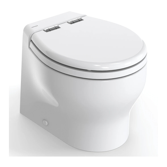
    Design and Flexi Line | installation et mode d’emploi | FRA 1. LES TOILETTES TECMA Les toilettes nautiques Tecma sont produits en Italie. Ils sont produits dans la circonscription de Civita Castellana où la production de sanitaires en céramique est renommée pour sa qualité...
  • Page 113: Nettoyage

    Design and Flexi Line | installation et mode d’emploi | FRA b) Courte description de la panne/problèmes constatés • La liste complète des centres d’assistance TECMA autorisés peut être téléchargée sur notre site www.thetfordmarine.com ou peut être demandée à notre service clients aux contacts suivants : DU MONDE: info@tecma.eu / Tel.
  • Page 114: Choix Du Papier

    Design and Flexi Line | installation et mode d’emploi | FRA Choix du papier Utiliser seulement du papier hygiénique. Le système est conçu pour disposer efficacement le papier hygiénique. Ne pas utiliser de chiffon en papier ou d'autres types. La société Tecma recommande l’utilisation de Thetford Aqua-Soft.
  • Page 115: Tableau De Commande Multiframe

    Design and Flexi Line | installation et mode d’emploi | FRA Tableau de commande Multiframe Opération Actionner le bouton « BEFORE USE » avant l’utilisation. Il remplira la cuvette avec une petite quantité d’eau. Actionner le bouton « AFTER USE » après l’utilisation, un cycle de lavage automatique démarrera au terme duquel la cuvette restera vide.
  • Page 116: Tableau De Commande Touch Sft

    Design and Flexi Line | installation et mode d’emploi | FRA Tableau de commande Touch SFT Opération Le panneau Touch SFT peut fonctionner à la fois en mode navigation et en mode amarrage. Le cycle de navigation en mode navigation élimine complètement la présence d’eau à l’intérieur du bateau en fin d’utilisation, évitant ainsi une éventuelle fuite d’eau à...
  • Page 117 Design and Flexi Line | installation et mode d’emploi | FRA MODALITÉ NAVIGATION : la cuvette des WC reste vide à la fin du cycle de rinçage Toucher l'emplacement 3. Toucher l'emplacement « AFTER 1. La « BEFORE USE » avant d'utiliser USE », après avoir utilisé...
  • Page 118: Changer Le Mode D'écoulement

    Design and Flexi Line | installation et mode d’emploi | FRA Changer le mode d'écoulement Le système est réglé en modalité navigation par défaut. Pour passer d'un mode à un autre: 1) Appuyez simultanément sur les boutons BEFORE USE et AFTER USE 2) Après 3 secondes, la LED du capteur de réservoir clignote: continuez d'appuyer sur 3) Après 5 secondes, les LED de périmètre clignotent: relâchez les boutons 4) La toilette effectuera automatiquement:...
  • Page 119 Design and Flexi Line | installation et mode d’emploi | FRA Fig.2: de l'amarrage à la navigation Appuyez simultanément sur les MODALITÉ deux boutons et maintenez-les AMARRAGE enfoncés. 2. Après 3 secondes, la LED du capteur de réservoir clignote. Continuez à appuyer. 3.
  • Page 120: Led D'état Du Réservoir - Fonction De Verrouillage

    Design and Flexi Line | installation et mode d’emploi | FRA LED d'état du réservoir - Fonction de verrouillage Le panneau de commande est équipé d’un voyant tricolore indiquant le niveau de remplissage du réservoir d’eau noire. Si le capteur de réservoir détecte que le niveau maximum a été...
  • Page 121: Désactivation Pour Nettoyage

    Design and Flexi Line | installation et mode d’emploi | FRA Désactivation pour nettoyage Pour nettoyer le tableau Touch, il est possible de désactiver temporairement les boutons. 1. Appliquer la main sur le tableau sans le toucher pendant 15 secondes. 2.
  • Page 122: Programmation De Rétroéclairage

    Design and Flexi Line | installation et mode d’emploi | FRA Programmation de rétroéclairage Il est possible de programmer le tableau Touch pour avoir le rétroéclairage : a. Toujours allumé b. Toujours éteint c. Activé par un capteur de proximité (par défaut) Instructions pour passer d'un programme à...
  • Page 123: Fonction Anti-Débordement

    Design and Flexi Line | installation et mode d’emploi | FRA Fonction anti-débordement Pour éviter les éventuels débordements liés à des entrées d'eau excessives consécutives avec le bouton "BEFORE USE", un blocage automatique est inséré qui ne permet pas d'effectuer plus de deux entrées consécutives. Le verrouillage est désactivé...
  • Page 124 Design and Flexi Line | installation et mode d’emploi | FRA ATTENTION : ne pas dépasser le niveau maximum de capacité du réservoir quand le Tank Level LED est rouge, mode lockout. ATTENTION : Si le sanitaire est branché à une prise d’eau de mer, s’assurer que le clapet à...
  • Page 125: Installation Et Maintenance

    Design and Flexi Line | installation et mode d’emploi | FRA 3. INSTALLATION ET MAINTENANCE ATTENTION : S’assurer d’avoir lu et compris toutes les mises en garde reportées dans ce document avant d’installer, utiliser ou intervenir sur le système. Si on ne tient pas compte de ces mises en garde, il y a le risque d’incident, dommages et éventuelle perte de l’embarcation, électrocution.
  • Page 126: Lieu D'installation

    Design and Flexi Line | installation et mode d’emploi | FRA ▪ Si le sanitaire est raccordé à une prise d’eau de mer, toutes les tuyauteries utilisées pour les différents branchements doivent être du type nautique et doivent être assurées à chaque connexion avec deux (2) colliers en acier inox. Ces colliers doivent être inspectés fréquemment pour en vérifier le serrage et par conséquent prévenir des fuites éventuelles.
  • Page 127 Design and Flexi Line | installation et mode d’emploi | FRA ▪ Vérifier que le modèle choisi soit conforme au lieu prévu à l’installation, en tenant compte de :  L’encombrement du pied  L’ouverture correcte du couvercle ▪ Qu’il y ait l’espace suffisant pour passer toutes les tuyauteries sans les endommager ou les plier de manière anomale ▪...
  • Page 128: Fixation Au Sol

    Design and Flexi Line | installation et mode d’emploi | FRA ▪ Dans le modèle EVOLUTION il y a les conditions pour installer la plaque de fixation verticale (non fournie) ou pour garantir une fixation appropriée à la charge prévue. Fixation au sol La fixation au sol de chaque cuvette de Flexi Ligne 2G et Design utilise des supports en nylon avec des vis latérales et ancrage au sol (sauf Xlight et Evolution avec le kit de montage...
  • Page 129: Ėlectrovanne

    Design and Flexi Line | installation et mode d’emploi | FRA Ėlectrovanne Avant le montage éliminer la saleté des tuyauteries (résidu de brasage, perles de soudure, copeaux métalliques, produit d’étanchéité). Un filtre à l'intérieur de l'électrovanne prévient des pannes causées par les impuretés de l'eau. Il est recommandé...
  • Page 130: Pompe De Remplissage

    Design and Flexi Line | installation et mode d’emploi | FRA Pompe de remplissage Installer la pompe de remplissage dans un lieu sec, aéré. La pompe ne peut pas être immergée ou exposée à des jets. Prévoir un fusible adéquat dans le circuit d’alimentation. La pompe peut être installée horizontalement et verticalement (dans ce cas l’orienter avec l’unité...
  • Page 131: Encastrement Pour Le Tableau De Commande Multiframe

    Design and Flexi Line | installation et mode d’emploi | FRA Encastrement pour le tableau de commande Multiframe REMARQUE : L'unité de contrôle Multiframe est fournie en standard avec le cadre de la série Bticino Living Light. Pour la compatibilité de Multiframe avec des cadres commerciaux, reportez-vous au tableau suivant : *Pour la série Gewiss Chorus, il est nécessaire de retirer les rabats du châssis B (voir figure).
  • Page 132: Capteurs Du Réservoir

    Design and Flexi Line | installation et mode d’emploi | FRA Capteurs du réservoir Le câblage des capteurs des unités de commande, à la fois dans la version standard à un niveau (gris / noir) et dans la version à deux niveaux pur le Touch (rouge / noir et blanc / vert) a une tension de 7 V.
  • Page 133: Équipement Nécessaire

    Design and Flexi Line | installation et mode d’emploi | FRA Pour l'installation, nettoyer la surface de la partie haute du reservoir - à la ligne de centre avec de l'alcool isopropylique (non fourni) où le capteur sera monté. Une fois bien propre et sec, placer le capteur en appuyant sur le point identifié.
  • Page 134 Design and Flexi Line | installation et mode d’emploi | FRA Fig. 1 ATTENTION : La ligne de flottaison en question devra être calculée en tenant compte des différents paramétrages durant la navigation. Voir l'exemple fig. 2. Fig. 2 ATTENTION : Suivre les réglementations en vigueur pour la conception et la réalisation des installations d’eaux usées et pour les procédures de vidage.
  • Page 135: Installation Centralisée - Eau Douce

    Design and Flexi Line | installation et mode d’emploi | FRA Installation Centralisée - Eau Douce Circuit hydraulique 3.8.1.1 Le cycle de vidage du WC nautique TECMA utilise l’eau douce du réservoir. Pour chaque WC, l'électrovanne peut être intégrée dans la cuvette, directement reliée à l’inlet/nozzle à...
  • Page 136: Installation Simple Et Multiple - Eau Salée

    Design and Flexi Line | installation et mode d’emploi | FRA Circuit électrique 110V/230V 3.8.1.3 Les produits Tecma avec moteur 110V/230V sont prévus avec une fiche à raccorder à l’alimentation. Schémas en sections A.3.6.5/6. Fiche Alimentation générale (moteur et électrovanne) - Shuko CEE/ US-Can Noir/Marron transformateur/centrale Noir/Bleu...
  • Page 137 Design and Flexi Line | installation et mode d’emploi | FRA Circuit électrique 3.8.2.2 Schéma en sections A.3.3/4. Chaque centrale est câblée en branchant Noir/Marron moteur cuvette Noir/Bleu Pompe de remplissage Noir/Gris Capteur réservoir Noir/Rouge Alimentation (avec fusible sur le rouge) La touche «...
  • Page 138 Design and Flexi Line | installation et mode d’emploi | FRA Eau mélangée à la Corps du Flange OD 60mm / buse de toilette mélangeur ID 42mm 42mm OD 55mm lenght Support de montage Poigneé joints + vis de montage Raccordement d'eau froid/chaude 3/8”...
  • Page 139 Design and Flexi Line | installation et mode d’emploi | FRA Option 1 : Melangueur et poignée intégrée à la toilette en céramique * Buse de Bidet Raccordement d'eau froid 3/8” c (à filetage femelle) Option 2 : Melangueur et poignée murale * Bude de Bidet - 3/8"...
  • Page 140: Résolution Des Problèmes

    Design and Flexi Line | installation et mode d’emploi | FRA Melanguer OD 42 mm Longeur 55 mm (crome) Le client est libre de sélectionner un mélangeur monté de mur de la même collection de la salle de bains et l'utiliser pour contrôler le bidet intégré dans les toilettes. Dans ce cas ne pas utiliser le mélangeur fourni et installer la console de mixage/poignée que vous préférez.
  • Page 141: Peut-On Utiliser Des Produits Acides Ou Agressifs

    Design and Flexi Line | installation et mode d’emploi | FRA En général, effectuez un entretien périodique de l'électrovanne et / ou des filtres de la pompe d'admission. Les produits antigel pour voitures ou les produits utilisés pour nettoyer les pare-brise ne sont pas recommandés.
  • Page 142: Appendix

    Design and Flexi Line | APPENDIX APPENDIX SPARE PARTS LIST / LISTA DEI RICAMBI Tecma S.r.l. T +39 0744 709071 Via Flaminia | Loc. Castello delle Formiche F +39 0744 719833 05030 Otricoli (TR) info@tecma.eu ITALY www.thetfordmarine.com...
  • Page 143 Design and Flexi Line | APPENDIX To find the closest service center please visit the website: www.thetfordmarine.com *Per scoprire il service centre più vicino a voi visitate il sito: * Para encontrar el centro de servicio más cercano, visite el sitio web: * Pour trouver le centre de service plus près, s'il vous plaît visitez le site de Web : www.thetfordmarine.com To order parts in North America, please refer to the list of spare parts and codes available...
  • Page 144 Design and Flexi Line | APPENDIX Tecma S.r.l. T +39 0744 709071 Via Flaminia | Loc. Castello delle Formiche F +39 0744 719833 05030 Otricoli (TR) info@tecma.eu ITALY www.thetfordmarine.com...
  • Page 145 Design and Flexi Line | APPENDIX - Seat and cover table / - Elenco dei coprisedile L is the length of the cover / L è la lunghezza del coperchio  Profile view of thermosetting:  Profile view of polyester: Vista di profilo del termoindurente Vista di profilo del poliestere Tecma S.r.l.
  • Page 146 Design and Flexi Line | APPENDIX Tecma S.r.l. T +39 0744 709071 Via Flaminia | Loc. Castello delle Formiche F +39 0744 719833 05030 Otricoli (TR) info@tecma.eu ITALY www.thetfordmarine.com...
  • Page 147 Design and Flexi Line | APPENDIX TECHNICAL DATA / DATI TECNICI MAC 11 110-125V AC 220-240V AC 12V DC 24V DC OUTLET PUMP 60Hz 50Hz or 60 Hz Fuse recommended 71.3 gpm Max 270L/min 36.1 ft Pump performance Max vertical head 11mt 295.3 ft Max horizontal distance 90 mt Outlet Duck bill valve (male)
  • Page 148 Design and Flexi Line | APPENDIX 220-240V AC 110-125V INLET SOLENOID 12V DC 24V DC 50Hz or 60 AC 60Hz Centralized system Power consumption 9.5 W 10 W Working pressure recommended 3 bar 3 bar 3 bar 3 bar Solenoid Inlet and Outlet (threaded female) 1/2"...
  • Page 149 Design and Flexi Line | APPENDIX SYSTEM DIAGRAMS / DIAGRAMMI DEGLI IMPIANTI A.3.1. Single System / Impianto Singolo Tecma S.r.l. T +39 0744 709071 Via Flaminia | Loc. Castello delle Formiche F +39 0744 719833 05030 Otricoli (TR) info@tecma.eu ITALY www.thetfordmarine.com...
  • Page 150 Design and Flexi Line | APPENDIX A.3.2. Multiple Single System / Impianto Singolo Multiplo Tecma S.r.l. T +39 0744 709071 Via Flaminia | Loc. Castello delle Formiche F +39 0744 719833 05030 Otricoli (TR) info@tecma.eu ITALY www.thetfordmarine.com...
  • Page 151: A.3.4. Multiple Single System Wiring / Cablaggio Impianto Singolo Multiplo

    Design and Flexi Line | APPENDIX A.3.3. Single System Wiring / Cablaggio Impianto Singolo A.3.4. Multiple Single System Wiring / Cablaggio Impianto Singolo Multiplo In case of installations other than those indicated in the diagrams, please contact Tecma for compatibility check. Tecma S.r.l.
  • Page 152: A.3.5. Centralized Fresh Water System / Impianto Centralizzato Acqua Dolce

    Design and Flexi Line | APPENDIX A.3.5. Centralized Fresh Water System / Impianto Centralizzato Acqua Dolce Tecma S.r.l. T +39 0744 709071 Via Flaminia | Loc. Castello delle Formiche F +39 0744 719833 05030 Otricoli (TR) info@tecma.eu ITALY www.thetfordmarine.com...
  • Page 153: A.3.6. Centralized Fresh Water Wiring / Cablaggio Centralizzato Acqua Dolce

    Design and Flexi Line | APPENDIX A.3.6. Centralized Fresh Water Wiring / Cablaggio Centralizzato Acqua Dolce 12 V/24 V with All In One Switch In case of installations other than those indicated in the diagrams, please contact Tecma for compatibility check. Tecma S.r.l.
  • Page 154: 24 V With Multiframe Switch

    Design and Flexi Line | APPENDIX 12 V/24 V with Multiframe Switch In case of installations other than those indicated in the diagrams, please contact Tecma for compatibility check. Tecma S.r.l. T +39 0744 709071 Via Flaminia | Loc. Castello delle Formiche F +39 0744 719833 05030 Otricoli (TR) info@tecma.eu...
  • Page 155: 24 V With Touch Sft Wall Switch

    Design and Flexi Line | APPENDIX 12 V/24 V with Touch SFT Wall Switch In case of installations other than those indicated in the diagrams, please contact Tecma for compatibility check. Tecma S.r.l. T +39 0744 709071 Via Flaminia | Loc. Castello delle Formiche F +39 0744 719833 05030 Otricoli (TR) info@tecma.eu...
  • Page 156: 230 V With All In One Switch

    Design and Flexi Line | APPENDIX 110 V/230 V with All In One Switch In case of installations other than those indicated in the diagrams, please contact Tecma for compatibility check. Tecma S.r.l. T +39 0744 709071 Via Flaminia | Loc. Castello delle Formiche F +39 0744 719833 05030 Otricoli (TR) info@tecma.eu...
  • Page 157: Sensors Connection Guide / Guida Alla Connessione Dei Sensori

    Design and Flexi Line | APPENDIX A.3.7. Sensors Connection Guide / Guida alla Connessione dei Sensori • All In One SFT 1P-2P / Multiframe SFT 2P: One level FIELD EFFECT GREY BROWN SENSOR FULL BLACK BLACK PNEUMATIC GREY BROWN SENSOR Pin1: Com FULL BLACK...

Ce manuel est également adapté pour:

Tecma flexi line

Table des Matières