Table des Matières
Publicité
Les langues disponibles
Les langues disponibles
Liens rapides
ALP 4.0 - MOTARD M4
Grazie per la fiducia accordata e buon divertimento. Con que-
sto libretto abbiamo voluto darLe le informazioni necessarie per
un corretto uso e una buona manutenzione della Sua moto.
I dati e le caratteristiche indicate sul presente manuale non impegnano la
BETAMOTOR S.p.A che si riserva il diritto di apportare modifiche e miglio-
ramenti ai propri modelli in qualsiasi momento e senza preavviso.
I
1
Publicité
Chapitres
Table des Matières

Manuels Connexes pour Betamotor ALP 4.0


Sommaire des Matières pour Betamotor ALP 4.0
- Page 1 Sua moto. I dati e le caratteristiche indicate sul presente manuale non impegnano la BETAMOTOR S.p.A che si riserva il diritto di apportare modifiche e miglio- ramenti ai propri modelli in qualsiasi momento e senza preavviso.
- Page 2 • pinza freno anteriore / posteriore • supporto parafango • bulloneria motore • bulloneria ammortizzatore • raggi ruota • telaietto posteriore • raccordi serbatoio olio su telaio AVVERTENZA In caso di interventi da eseguire sulla moto rivolgersi alla catena di assistenza autorizzata Betamotor.
-
Page 3: Table Des Matières
Avvertenze sull’uso del veicolo ..............5 Guida ecologica ................... 5 Guida sicura ..................6 CAP. 1 INFORMAZIONI GENERALI ..........7 Dati identificazione veicolo ..............8 Fornitura ....................8 Carico ....................9 Pneumatici .................... 9 Conoscenza del veicolo ................ 11 Chiavi e serrature ................. 12 Commutatore / bloccasterzo .............. - Page 4 Manutenzione programmata ..............61 Lunga inattività del veicolo ..............62 Dopo un lungo periodo di inattività ............62 CAP. 4 REGOLAZIONI .............. 63 Regolazione freni ................. 64 Regolazione frizione ................64 Regolazione ammortizzatore posteriore ............ 65 Regolazione minimo ................65 Regolazione gioco gas .................
-
Page 5: Avvertenze Sull'uso Del Veicolo
AVVERTENZE SULL’USO DEL VEICOLO • Il veicolo deve essere obbligatoriamente corredato di: targa, libretto di circolazio- ne, bollo ed assicurazione. • È vietato il trasporto di animali e oggetti non resi solidali al veicolo, che “escano” dall’ingombro del veicolo stesso e che superino il carico previsto dal Costruttore. •... -
Page 6: Guida Sicura
GUIDA SICURA • Rispettare il Codice Stradale • Indossare sempre casco omologato ed allacciato • Mantenere sempre pulita la visiera protettiva • Indossare indumenti senza estremità penzolanti • Non viaggiare con in tasca oggetti acuminati o fragili • Regolare correttamente lo specchietto retrovisore •... -
Page 7: Cap. 1 Informazioni Generali
INDICE ARGOMENTI CAP. 1 INFORMAZIONI GENERALI Dati identificazione veicolo Fornitura Carico Pneumatici Conoscenza del veicolo Chiavi e serrature Commutatore / bloccasterzo Serratura casco Cruscotto e comandi Dati tecnici Schema elettrico Dispositivi elettrici... -
Page 8: Dati Identificazione Veicolo
DATI IDENTIFICAZIONE VEICOLO IDENTIFICAZIONE TELAIO I dati di identificazione A sono impressi sul canotto dello sterzo nel lato destro. IDENTIFICAZIONE MOTORE I dati di identificazione B del motore sono impressi nella zona indicata in figura. ATTENZIONE: l’alterazione dei numeri di identificazione è... - Page 9 • Effettuare il controllo della pressione ogni 15 giorni. • Verificare la pressione solamente a pneu- matici freddi. pressione giusta PNEUMATICI ALP 4.0 PNEUMATICO ANT. POST. Dimensioni (90/90-21) (140/80-18) 70R o (130/80-18) 66R...
- Page 10 Nota: Lo spessore minimo del battistrada dei pneumatici (TUBE TYPE) non deve mai essere inferiore ai 2 mm. La mancata adempienza a questa norma è punita ai sensi di legge. • Controllare prima di ogni viaggio che i pneumatici non presentino tagli, screpola- ture, abrasioni, rigonfiamenti, ecc...
-
Page 11: Conoscenza Del Veicolo
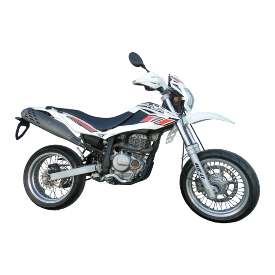
CONOSCENZA DEL VEICOLO ALP 4.0 MOTARD M4 Elementi principali: 8- Fanale posteriore 17 - Sella 1- Filtro aria 9- Indicatori di dire- 18 - Motore 2- Serbatoio carbu- zione posteriori 19 - Parafango ante- rante 10 - Cavalletto laterale riore... -
Page 12: Chiavi E Serrature
CHIAVI E SERRATURE Il veicolo viene fornito con due chiavi e le relative scorte da utilizzarsi per il commu- tatore/bloccasterzo e per la serratura casco. ATTENZIONE: Non conservare la chiave di scorta all’interno del veicolo, ma in luogo sicuro ed a portata di mano. -
Page 13: Cruscotto E Comandi
CRUSCOTTO E COMANDI 1- LCD 10 - Pulsante accensione 2- Commutatore a chiave 11 - Pulsante stop motore 3- Spia folle 12 - Pulsante indicatori di direzione 4- Spia indicatori di direzione 13 - Pulsante clacson 5- Spia abbaglianti 14 - Deviatore luci 6- Spia cavalletto 15 - Passing 7- Leva frizione... -
Page 14: Lcd
INDICAZIONI SU LCD Funzionamento e visualizzazione pagine VELOCITÀ ISTANTANEA ODO – TOTALIZZATORE TRP – TOTALIZZATORE PARZIALE AVS – VELOCITÀ MEDIA DEL PERCORSO TRP LAP – CRONOMETRO NEI FORMATI hh:mm:ss e mm:ss:1/10s CLK – OROLOGIO NEI FORMATI hh:mm:ss, con 12h e 24h, e mm:ss BARRA CONTAGIRI SPEED max –... - Page 15 Successione pagine su LCD Tutte le pagine a partire dalla pagina di default sono raggiungibili solo nella loro sequenza. Pagina 1 - TEST. Girare il commutatore a chiave su ON. Verifica globale di tutti i segmenti e di tutte le icone presenti su LCD e test sugli indicatori luminosi.
- Page 16 Dalla pagina 2 con MODE a mezzo Pagina 3 - TRP fermo o SCROLL con veicolo in movimen- to, premendoli brevemente, si passa alla pagina 3. Il passaggio avviene al rilascio del comando. Visualizza: Velocità istantanea in alto (max 199 Km/h o Mph) TRP Totalizzatore parziale visualiz- zata in basso (max 999.9 Km o Miglia).
- Page 17 Dalla pagina 5, premendo SCROLL per Pagina 6 - LAP – Cronometro minuti:secondi:decimi di secondo un tempo di 1,5”, si presenta per la dura- ta di 1” la figura 21 con le barre - - : - - in alto Mantenendo premuto SCROLL si ripresen- ta la pagina 5.
- Page 18 Da pagina 7 con MODE a mezzo fermo Pagina 8 - CLK - Orologio minuti:secondi o SCROLL in movimento, premendoli bre- vemente si passa alla pagina 8. Il passaggio avviene al rilascio del comando. Visualizza: Orologio formato MINUTI:SECONDI 00:00 in alto. Regolabile tramite pulsante MODE o SCROLL su minuti e secondi solo a mez- zo fermo.
- Page 19 Cancellazione parametri TRP, SPEED max, LAP I parametri cancellabili sono: - Percorso indicato da TRP e conseguentemente AVS - SPEED max velocità massima raggiunta Tempi indicati da LAP in entrambe le configurazioni da una qualsiasi delle 2 pagine. La cancellazione dei parametri è attuabile con MODE a mezzo fermo e con SCROLL sempre.
- Page 20 ICONA BATTERIA Vb MAGGIORE DI 14,5V Il lampeggio della barra verticale con pre- sente la scritta max indica che la tensio- ne della batteria è maggiore di 14,5V. Se la segnalazione persiste occorre verificar- ne la causa. Rivolgersi ad un concessio- nario Betamotor autorizzato.
-
Page 21: Verifica Del Contenuto Attivo Delle Icone Di Sorveglianza
ICONA BATTERIA Vb MINORE DI 10,5V Il lampeggio sia della barra verticale che della batteria con presente la scritta min indica che la tensione della batteria è mi- nore di 10,5V. Se la segnalazione persi- ste occorre verificarne la causa. ATTENZIONE. -
Page 22: Dati Tecnici
........................ PNEUMATICI - MOTARD M4 pressione bar ant. 2,0/post. 2,2 ........................ DIMENSIONI RUOTE - ALP 4.0 copertura anteriore ............(90/90-21) 54R copertura posteriore ......(140/80-18) 70R o (130/80-18) 66R cerchio anteriore ................1,85x21 cerchio posteriore ................ 3,00x18 DIMENSIONI RUOTE - MOTARD M4 copertura anteriore ............ - Page 23 ..............101 mm (ALP 4.0) 58 mm (MOTARD M4) SOSPENSIONE POSTERIORE monoammortizzatore con regolazione precarico molla corsa ammortizzatore ............83 mm (ALP 4.0) 100 mm (MOTARD M4) FRENO ANTERIORE - ALP 4.0 a disco Ø 260 mm con comando idraulico FRENO ANTERIORE - MOTARD M4 a disco Ø...
- Page 24 Cambio ........6 marce ad ingranaggio costante (350 cc) Valvole ..................... n. 4 Trasmissione secondaria ............15/48 (ALP 4.0) 15/42 (MOTARD M4) Catena con O-Ring......REGINA DERVIO 5/8’ - passi 112 (ALP 4.0) REGINA DERVIO 5/8’ - passi 110 (MOTARD M4)
- Page 25 Grasso per tiranterie ............BARDAHL MPG2 Gioco valvole ..........aspirazione 0,05 - 0,10 mm scarico 0,8 - 0,13 mm Avviamento ................... elettrico...
-
Page 26: Schema Elettrico
SCHEMA ELETTRICO... -
Page 27: Legenda Schema Elettrico
LEGENDA SCHEMA ELETTRICO LAMPEGGIATORE ANTERIORE DESTRO CON LAMPADA 12V-10W PULSANTE STOP ANTERIORE GRUPPO COMANDI DESTRO ARRESTO MOTORE PULSANTE AVVIAMENTO SENSORE GIRI RUOTA SPIA LUCE ABBAGLIANTI SPIA LAMPEGGIATORI DISPLAY SPIA FOLLE SPIA CAVALLETTO PULSANTE SCROLL PULSANTE CLACSON DEVIO LUCI SPRAZZO LUCI COMMUTATORE LAMPEGGIATORI GRUPPO COMANDO SINISTRO PULSANTE FRIZIONE... -
Page 28: Dispositivi Elettrici
DISPOSITIVI ELETTRICI Togliere la sella girando l’apposita vite bloccaggio di 1/4 di giro in senso antiorario e facendola scorrere indietro. ATTENZIONE: Per evitare danni all’impianto elettrico, non scollegare mai i cavi con il motore in moto. RELÉ CAVALLETTO A FUSIBILE B - due da 20A ATTENZIONE: Prima di sostituire il fusibile interrotto, ricercare ed eliminare il guasto che ne... - Page 29 NOTE RELATIVE ALLA BATTERIA G Inserire la batteria nell’apposita sede sottosella (posizione come da foto) fissandola con l’elastico di corredo H. Collegare il terminale del cavo di colore nero al negativo (-) e il cavo di colore rosso al positivo (+) inserendo il cappuccio rosso di protezione. Rimontare la sella.
-
Page 31: Cap. 2 Utilizzo Del Veicolo
INDICE ARGOMENTI CAP. 2 UTILIZZO DEL VEICOLO Controlli e manutenzione prima e dopo l’utilizzo in fuoristrada Lubrificanti consigliati Rodaggio Avviamento del motore Arresto del motore Rifornimento carburante... -
Page 32: Lubrificanti Consigliati
CONTROLLI E MANUTENZIONE PRIMA E DOPO L’UTILIZZO IN FUORISTRADA Onde evitare spiacevoli inconvenienti durante il funzionamento del veicolo è consigliabile effettuare, sia prima che dopo l’utilizzo, alcune operazioni di controllo e manutenzione. Infatti pochi minuti dedicati a queste operazioni, oltre a rendere la guida più... -
Page 33: Rodaggio
RODAGGIO Il rodaggio ha una durata di circa 10 ore di attività, durante questo periodo si con- siglia di: • Utilizzare il veicolo dopo aver fatto scal- dare bene il motore • Evitare di viaggiare a velocità costante (variando la velocità i vari componenti si assesteranno uniformemente ed in minor tempo). -
Page 34: Avviamento Del Motore
AVVIAMENTO DEL MOTORE • Ruotare la chiave nel commutatore in sen- so orario ed assicurarsi che la spia del folle (N), posta sul cruscotto, sia accesa. AVVERTENZA: Ricordarsi, prima di girare la chiave, di posizionare il pulsante deviatore luci in posizione anabbagliante (vedi pag. -
Page 35: Arresto Del Motore
Nota: L’avviamento avviene anche con il caval- letto abbassato, purché sia accesa la spia del folle (N). Nota: In caso di emergenza, questo veicolo può funzionare anche senza l’uso della batte- ria. ARRESTO DEL MOTORE • Da fermo e con il cambio in folle, ruotare la chiave nel commutatore in posizione “OFF”. -
Page 36: Rifornimento Carburante
RIFORNIMENTO CARBURANTE •Spegnere il motore. • Rimuovere il tappo A. Nota: La capacità del serbatoio è di circa 10,5 litri di cui 3 di riserva. ATTENZIONE: Eventuali trabocchi di benzina sulla car- rozzeria o su altre parti, devono essere prontamente asciugati. Prima di effettuare il rifornimento benzina, spegnere il motore. -
Page 37: Cap. 3 Controlli E Manutenzione
INDICE ARGOMENTI CAP. 3 CONTROLLI E MANUTENZIONE Controllo livello olio motore Sostituzione olio motore e filtro olio Tubo raccolta fumi Olio pompa freni, spurgo freni Olio forcelle Filtro aria Candela Freni: anteriore, posteriore Carburatore Batteria Rimozione delle plastiche Note per fuoristrada Sostituzione gruppo trasmissione finale Pulizia del veicolo e controlli Controlli dopo la pulizia... -
Page 38: Controllo Livello Olio Motore
CONTROLLO LIVELLO OLIO MOTORE Livello dell’olio del motore Su questo veicolo, il controllo dell’olio deve essere effettuato a motore caldo, in quanto il serbatoio olio è posto in alto rispetto al moto- re (vedi schema). Fig. B Fig. A Procedura controllo livello olio •... - Page 39 Controllo livello olio Da effettuare solo dopo aver verificato la presenza dell’olio nel motore (vedi pag. 38). • Avviare il motore e farlo girare al minimo per tre minuti. • Spegnere il motore ed aspettare un mi- nuto. • Togliere il tappo del bocchettone di riem- pimento dell’olio.
-
Page 40: Sostituzione Olio Motore E Filtro Olio
SOSTITUZIONE OLIO MOTORE E FIL- TRO OLIO Eseguire sempre la sostituzione dell’olio a motore caldo, facendo attenzione a non toccare il motore e l’olio stesso onde evi- tare scottature. • La sostituzione del filtro olio dovrebbe essere fatta insieme alla sostituzione del- l’olio. - Page 41 Svuotamento olio dal serbatoio • Togliere le 4 viti di fissaggio carter po- steriore motore. • Svitare la vite Q e far defluire tutto l’olio dal serbatoio. • Si consiglia, al primo cambio d’olio (vedi pag. 33), di effettuare anche la pulizia del filtro metallico, posto sulla parte fina- le del serbatoio olio.
- Page 42 • Per lo svuotamento totale dell’olio anche dal serbatoio, togliere la sella, le fiancate anteriori e il serbatoio. • Inclinare la moto sul lato sinistro e svitare la vite H posta sul telaio. • Applicare un tubo di gomma I. •...
- Page 43 Montaggio • Procedere in senso inverso alle operazio- ni di smontaggio del filtro a rete metalli- ca del serbatoio olio. • Inserire un nuovo filtro olio. • Applicare leggermente olio motore all’O- Ring del coperchio filtro prima dell’inseri- mento. • Inserire il coperchio filtro olio, dopo aver montato molla ed O-Ring e serrare le tre viti di fissaggio.
-
Page 44: Tubo Raccolta Fumi
TUBO RACCOLTA FUMI Il tubo raccolta fumi A è situato sulla parte sinistra del veicolo vicino all’ammortizza- tore, esce dalla parte inferiore della sca- tola filtro e raccoglie i gas prodotti dal- l’olio motore. Nel caso si riscontrasse la presenza di olio all’interno del tubo, que- sto deve essere svuotato, togliendo il tap- po all’estremità... - Page 45 Freno posteriore Controllare attraverso il contenitore olio E, la presenza dell’olio. Il livello dell’olio non deve mai essere inferiore alla tacca F di livello minimo in rilievo sul contenitore. Per ripristinare il livello procedere come de- scritto: • Rimuovere la vite di fissaggio del conte- nitore olio G.
- Page 46 Spurgo freno anteriore Per lo spurgo aria dal circuito del freno anteriore procedere come segue: • Togliere il cappuccio di gomma A dalla valvola B. • Aprire il tappo della vaschetta olio. • Inserire un’estremità di un tubicino nella valvola B, e l’altra all’interno di un conte- MOTARD nitore.
- Page 47 Spurgo freno posteriore Per lo spurgo aria dal circuito del freno posteriore procedere come segue: • Togliere il cappuccio di gomma C. • Aprire il tappo della vaschetta olio. • Inserire un’estremità di un tubicino nella valvola, e l’altra all’interno di un conteni- tore D.
-
Page 48: Olio Forcelle
La descrizione relativa alla sostituzione dell’olio delle forcelle riveste un carattere puramente informativo. Infatti è consi- gliabile rivolgersi ad un’officina autorizzata BETAMOTOR per effettuare questa opera- zione. Per la sostituzione procedere nel modo seguente: 1) Togliere il manubrio, svitando le quattro viti C di fissaggio dei due cavallotti D. -
Page 49: Filtro Aria
FILTRO ARIA Per accedere al filtro è necessario: • Alzare leggermente la fiancata sinistra posteriore A, come in figura. • Smontare la copertura di plastica E svi- tando le 3 relative viti di fissaggio B. • Togliere il filtro C svitando la vite di fis- saggio D del coperchio ferma filtro. -
Page 50: Candela
CANDELA Mantenere la candela in buono stato con- tribuisce alla diminuzione dei consumi e all’ottimale funzionamento del motore. E’ preferibile rimuovere la candela a mo- tore caldo (ovviamente spento) in quanto i depositi carboniosi e la colorazione del- l’isolamento forniscono importanti indica- zioni sulla carburazione, sulla lubrificazio- ne e sullo stato generale del motore. -
Page 51: Freno Anteriore
FRENO ANTERIORE Controllo Per verificare lo stato di usura del freno anteriore è sufficiente visionare la pinza dalla parte anteriore, dove è possibile in- travedere le estremità delle due pastiglie che dovranno presentare almeno uno spes- sore di 2 mm di ferodo. Nel caso lo strato fosse inferiore procedere immediatamen- te alla loro sostituzione. -
Page 52: Carburatore
AVVERTENZA: Queste descrizioni sono a carattere pura- mente informativo. Infatti è consigliabile rivolgersi ad un’offi- cina autorizzata BETAMOTOR. BATTERIA Verificare lo stato di carica della batteria, misurando la tensione con batteria a ripo- so “Veicolo spento” con un voltmetro. - Page 53 RIMOZIONE DELLE PLASTICHE PER ALP Per effettuare agevolmente i controlli od interventi in alcune zone del veicolo, è in- dispensabile smontare le parti componen- ti la carrozzeria nel modo seguente: Smontaggio sella • Svitare la vite di fissaggio A e togliere la sella sfilandolo verso la parte posteriore in modo da farla uscire dal gancio po- sto sul serbatoio.
- Page 54 Smontaggio fiancate posteriori • Svitare le viti N di fissaggio, dopo aver tolto le maniglie posteriori e quindi sfila- re le fiancate. Smontaggio serbatoio carburante • Svitare la vite I di fissaggio al telaio, ri- muovere il tubo del rubinetto carburante e togliere il serbatoio, sfilandolo verso la parte posteriore.
- Page 55 RIMOZIONE DELLE PLASTICHE PER MOTARD M4 Per effettuare agevolmente i controlli od in- terventi in alcune zone del veicolo, è indi- spensabile smontare le parti componenti la carrozzeria nel modo seguente: Smontaggio sella • Svitare la vite di fissaggio A e togliere la sella sfilandolo verso la parte posteriore in modo da farla uscire dal gancio posto sul serbatoio.
- Page 56 Smontaggio fiancate posteriori • Dopo aver rimosso le fiancatine anteriori e i maniglioni è possibile procedere allo smontaggio delle plastiche posteriori M svi- tando i due fissaggi laterali N dopodiche rimuovere le tre viti O, sfilare le fiancatine sbloccandole dagli incastri. Smontaggio codino posteriore •...
-
Page 57: Note Per Fuoristrada
NOTE PER FUORISTRADA Per un utilizzo del veicolo in fuoristrada è possibile smontare le parti ritenute ingom- branti come: il portatarga, il cavalletto, l’in- dicatore di direzione e le pedane passeg- gero. Smontaggio cavalletto • Rimuovere l’interruttore cavalletto svitan- do l’unica vite di fissaggio C. •... -
Page 58: Sostituzione Gruppo Trasmissione Finale
SOSTITUZIONE GRUPPO TRASMISSIO- NE FINALE In caso di necessità di sostituzione per usura di uno dei tre componenti della tra- smissione finale (pignone, catena e coro- na), si consiglia sempre la sostituzione dell’intero gruppo. Sostituzione catena • Agire con un cacciavite a taglio, come mostrato in figura. - Page 59 Sostituzione pignone catena • Allentare la ruota posteriore. • Allentare i registri catena. • Far avanzare la ruota fino a fine corsa, in modo da poter allentare la catena. • Svitare le 2 viti F di fissaggio del coper- chietto. •...
-
Page 60: Pulizia Del Veicolo E Controlli
PULIZIA DEL VEICOLO E CONTROLLI Per ammorbidire lo sporco e il fango depositato sulle superfici verniciate usare un getto di acqua. Una volta ammorbiditi, fango e sporcizia sono asportabili con una spugna soffice per carrozzeria imbevuta di molta acqua e “shampoo” (2-4% di shampoo in acqua). -
Page 61: Manutenzione Programmata
* si raccomanda il serraggio dopo ogni utilizzo in fuoristrada legenda: c - controllo (pulizia, regolazione, lubrificazione, sostituzione se necessari) s - sostituzione r- re golazione p - pulizia t - serra ggio AVVERTENZA: In caso di interventi da eseguire sulla moto rivolgersi alla catena di Assistenza Autorizzata BETAMOTOR. -
Page 62: Lunga Inattività Del Veicolo
LUNGA INATTIVITÀ DEL VEICOLO In previsione di un lungo periodo di inattività del veicolo, ad esempio durante la stagione invernale, è necessario adottare alcuni semplici accorgimenti a garanzia di un buon mantenimento: • Eseguire un’accurata pulizia del veicolo in tutte le sue parti. •... -
Page 63: Cap. 4 Regolazioni
INDICE ARGOMENTI CAP. 4 REGOLAZIONI Regolazione freni Regolazione frizione Regolazione ammortizzatore posteriore Regolazione minimo Regolazione gioco gas Controllo e regolazione gioco sterzo Tensionamento catena Fascio luminoso... -
Page 64: Regolazione Freni
REGOLAZIONE FRENI Freno anteriore Il freno anteriore è del tipo a disco con comando idraulico per cui non necessita di alcun intervento di regolazione. Freno posteriore Il freno posteriore è del tipo a disco con comando idraulico. E’ possibile variare la posizione del peda- le in altezza intervenendo sui registri A e Mantenere un gioco minimo di 5 mm sul- la leva. -
Page 65: Regolazione Ammortizzatore Posteriore
Una volta trovata la regolazione ottimale, serrare la ghiera B e la controghiera A. ATTENZIONE: Per la regolazione dell’ammortizzatore posteriore ALP 4.0, considerare che la lun- ghezza della molla con precarico standard è di 194 mm, mentre la lunghezza della molla dell’ammortizzatore posteriore del MOTARD M4 con precarico standard è... -
Page 66: Controllo E Regolazione Gioco Sterzo
CONTROLLO E REGOLAZIONE GIO- CO STERZO Verificare periodicamente il gioco del cannotto di sterzo muovendo avanti e in- dietro le forcelle come illustrato in figura. Qualora si avverta del gioco, procedere alla regolazione operando nel modo se- guente: • Svitare le 4 viti C. •... -
Page 67: Tensionamento Catena
TENSIONAMENTO CATENA Per una più lunga durata della catena di trasmissione è opportuno controllare pe- riodicamente la sua tensione. Tenerla sempre pulita dalla sporcizia de- positata e lubrificarla. Se il gioco della catena supera i 20 mm procedere al suo tensionamento. •... -
Page 68: Fascio Luminoso
FASCIO LUMINOSO • La regolazione del fascio luminoso avviene manualmente dopo aver svitato una chiave a brugola le viti poste sui lati del gruppo ottico • L’orientamento del fascio luminoso va verificato periodicamente. La regolazione è soltanto verticale • Porre il veicolo (in piano, ma non sul cavalletto) a 10 m da una parete verticale •... -
Page 69: Cap. 5 Sostituzioni
INDICE ARGOMENTI CAP. 5 SOSTITUZIONI Sostituzione pastiglie freno anteriore Sostituzione pastiglie freno posteriore Sostituzione lampada faro ALP Sostituzione lampada faro MOTARD Sostituzione lampade indicatori di direzione... -
Page 70: Sostituzione Pastiglie Freno Anteriore
è consigliabile rivolgersi ad un’officina autorizzata BETAMOTOR per effettuare questa opera- zione. FRENO ANTERIORE PER ALP 4.0 Per la sostituzione occorre procedere nel seguente modo: • Smontare la pinza svitando le due viti A • Svitare le due viti B •... - Page 71 FRENO ANTERIORE PER MOTARD M4 Per la sostituzione occorre procedere nel seguente modo: • Smontare la pinza dal supporto speciale C, svitando le due viti A. • Svitare le due viti B. • Estrarre le pastiglie. ATTENZIONE: Durante lo smontaggio della pinza freno anteriore fare attenzione a non danneg- giare il sensore C.
-
Page 72: Sostituzione Pastiglie Freno Posteriore
La descrizione relativa alla sostituzione delle pastiglie, riveste un carattere pura- mente informativo; infatti è consigliabile rivolgersi ad un’officina autorizzata BETAMOTOR per effettuare questa opera- zione. Per la sostituzione occorre procedere nel seguente modo: • Posizionare la moto su un cavalletto cen- trale, con la ruota posteriore sollevata da terra. -
Page 73: Sostituzione Lampade Faro Alp
SOSTITUZIONE LAMPADA FARO ALP ANTERIORE Rimuovere le tre viti di fissaggio e la corni- ce del faro. Rimuovere le tre viti A che fissano la para- bola ed estrarla. Sfilare il connettore della lampada. Ruotare il blocco della lampada in senso antiorario ed estrarre la lampada brucia- Inserire una lampada nuova avendo cura di non toccarne il bulbo per evitare di com-... -
Page 74: Sostituzione Lampade Faro Motard
SOSTITUZIONE LAMPADA FARO MOTARD M4 ANTERIORE Per sostiture la lampada del proiettore staccare i connettori A dalla lampadina e togliere la calotta di gomma B. Ruotare in senso antiorario la flangia di fissaggio C e togliere la lampadina dalla parabola. Inserire la lampadina nuova (12V - 55/ 60W) avendo cura di non toccare il bulbo per evitare di comprometterne l'efficienza... -
Page 75: Sostituzione Lampade Indicatori Di Direzione
30° e successivamente estrarle. Lampada proiettore 12V-55/60W Luce posizione 12V-5W Lampada indicatori di direzione destro/sinistro 12V-10W anteriore/posteriore (solo per ALP 4.0) Lampada fanale posteriore (solo per ALP 4.0) 12V-5/21W Lampada luce targa 12V-5W... -
Page 77: Cap. 6 Cosa Fare In Caso Di Emergenza
INDICE ARGOMENTI CAP. 6 COSA FARE IN CASO DI EMERGENZA INDICE ALFABETICO... - Page 78 INCONVENIENTE CAUSA RIMEDIO - Impianto di alimentazione Effettuare la pulizia dell’impianto Il motore non si avvia carburante ostruito (tubi, serbatoio benzina, rubinetto) - Filtro aria eccessivamente Operare come indicato a pag. 49 sporco - Non arriva corrente alla candela Effettuare la pulizia o la sostituzione della candela.
- Page 79 Avviamento ..................34 Candela ..................... 50 Carburatore ..................52 Chiavi e serrature ................. 12 Commutatore / bloccasterzo ..............12 Controlli dopo la pulizia ................ 60 Controlli e manutenzione prima e dopo utilizzo in fuoristrada ....... 32 Cruscotto e comandi ................13 Dati identificazione veicolo ..............
- Page 80 ..........................................................................................................................................................................................................................................................................................................................................................................................................................................................................................................................................................................................................................................................................................................................................
- Page 81 The data and specifications provided in this manual does not constitute an engagement on the part of BETAMOTOR S.p.A. BETAMOTOR reserves the right to make any changes and improvements to its models at any moment and without notice.
-
Page 82: Important
• front / rear brake caliper • mudguard bracket • engine bolts • shock absorber bolts • wheel spokes • rear frame • oil tank joints on frame IMPORTANT For any servicing requirements, please get in contact with Betamotor’s authorized service network. - Page 83 Operating instructions ................85 Ecologic guide ..................85 Riding safety ..................86 CHAPTER 1 GENERAL INFORMATION .......... 87 Vehicle identification data ..............88 Delivery .................... 88 Load ....................89 Tyres ....................89 Familiarizing with your vehicle ............... 91 Keys and locks ................... 92 Ignition switch / Steering lock ...............
- Page 84 Scheduled maintenance ..............141 Prolonged inactivity ................142 After prolonged inactivity ..............142 CHAPTER 4 ADJUSTMENTS ............143 Adjusting the brakes ................144 Adjusting the clutch ................144 Rear shock absorber regulation ............. 145 Adjusting the slow running ..............145 Adjusting the throttle play ..............
-
Page 85: Operating Instructions
OPERATING INSTRUCTIONS • The vehicle must be accompanied by: number-plate, registration document, tax disc and insurance. • Do not carry any animals or objects which are not securely fastened to the vehicle, or exceed the vehicle’s overall dimensions or the maximum load specified by the manufacturer. -
Page 86: Riding Safety
RIDING SAFETY • Observe the Highway Code. • Always put on and fasten a homologated helmet. • Always keep the crash helmet visor clean. • Avoid wearing garments with hanging ends. • Do not keep sharp or brittle objects in your pockets while riding. •... - Page 87 CONTENTS CHAPTER 1 GENERAL INFORMATION Vehicle identification data Delivery Load Tyres Familiarizing with your vehicle Keys and locks Ignition switch / Steering lock Crash helmet lock Instrument panel and controls Specifications Wiring diagram Electrical devices...
-
Page 88: Frame Identification
VEHICLE IDENTIFICATION DATA FRAME IDENTIFICATION Frame identification data A are stamped on the right side of the steering head tube. ENGINE IDENTIFICATION Engine identification data B are stamped in the area shown in the figure. WARNING: Tampering with the identification numbers is severely punished by law. -
Page 89: Load
• Check the tyre pressures every other week. • Always measure the inflating pressures when the tyres are cold. pressure is correct TYRES ALP 4.0 TYRE FRONT REAR Size (90/90-21) (140/80-18) 70R or (130/80-18) 66R... - Page 90 Note: The tyre (TUBE TYPE) tread depth must never be less than 2 mm. Failure to comply with this rule is punished under the regulations in force. • Before riding, check the tyres for cuts, cracks, abrasions, bulges, etc. If any defects are found, have the tyres checked by an expert as riding with a damaged tyre can be extremely dangerous.
-
Page 91: Familiarizing With The Vehicle
FAMILIARIZING WITH THE VEHICLE ALP 4.0 MOTARD M4 Main parts: 8- Rear light 17- Saddle 1- Air filter 9- Rear turn indicators 18- Engine 2- Fuel tank 10- Side stand 19- Front mudguard 3- Tank cap 11- Crash helmet lock... -
Page 92: Keys And Locks
KEYS AND LOCKS The vehicle is supplied with two keys and the related spares for the ignition switch/ steering lock and the crash helmet lock. WARNING Do not keep the spare keys in the vehicle. Keep the keys in a safe and easy-to-reach place. -
Page 93: Instrument Panel And Controls
INSTRUMENT PANEL AND CONTROLS 1- LCD 10 - Engine start button 2- Ignition switch 11 - Engine stop button 3- Neutral warning light 12 - Turn indicator switch 4- Turn indicator warning light 13 - Horn button 5- High beam warning light 14 - Lights selector switch 6- Stand warning light 15 - High beam flash switch... -
Page 94: Lcd Display
LCD DISPLAY Operation and display of pages and icons ISTANT SPEED ODO – TOTAL COUNTER TRP – TRIP COUNTEER AVS – TRP AVERAGE SPEED LAP – STOPWATCH (FORMATS CLK – CLOCK FORMATS hh:mm:ss, con 12h e 24h, e mm:ss TACHOMETER BARS SPEED max –... - Page 95 Order of pages on LCD display The different pages can only be viewed in succession starting from the default page. Page 1 - TEST Turn the ignition switch to the ON posi- tion. General check of all the icons and bars on the LCD display and warning light test.
- Page 96 While page 2 is displayed, briefly press Page 3 - TRP MODE if the vehicle is stationary or SCROLL while travelling to bring up page The new page is displayed as soon as the button is released. Displays: Instant speed at the top (max. 199 km/h or Mph) TRP Trip counter, displayed at the bot- tom (max.
- Page 97 Pressing SCROLL for 1.5 seconds while page 5 is displayed brings up figure 21 for 1 sec- Page 6 - LAP – Stopwatch ond with the bars minutes:seconds:tenths of a second - - : - - :- - at the top. Holding down SCROLL brings up page 5 again.
- Page 98 While page 7 is displayed, briefly press Page 8 - CLK - Clock minutes:seconds MODE if the vehicle is stationary or SCROLL while travelling to bring up page 8. The new page is displayed as soon as the button is released. Displayed information: Clock format MINUTES:SECONDS 00:00...
- Page 99 Resetting the TRP, SPEED max and LAP parameters. The following parameters can be reset: - TRP, trip counter, and consequently AVS. - SPEED max, maximum speed reached by the vehicle. Times indicated by LAP in both configurations while either of the two pages is displayed. The parameters can be reset by pressing the MODE button while the vehicle is stationary or the SCROLL button at all time.
- Page 100 As soon as the preset value is reached, the icon starts to blink. Contact an authorized Betamotor dealer. SERVICE ICON When 90 per cent of the hours or kilome- tres making up the preset service interval have been totalled, the service icon is dis- played steadily on all pages.
-
Page 101: Checking The Active Contents Of The Monitoring Icons
BATTERY ICON - Vb LESS THAN 10.5 V When the vertical bar blinks and min is displayed, the battery voltage is less than 10.5 V. If the indication persists, the cause will have to be determined. IMPORTANT: If the battery is disconnect- ed or its voltage is nearly zero, the instru- ment loses its functionality. -
Page 102: Specifications
............front 1.5/rear 1.8 TYRES - MOTARD M4 pressure kg/cm ............front 2.0 / rear 2.2 WHEEL DIMENSION - ALP 4.0 front cover ............... (90/90-21) 54R rear cover ......... (140/80-18) 70R or (130/80-18) 66R front rim ..................1.85x21 rear rim ..................3.00x18 WHEEL DIMENSION - MOTARD M4 front cover .............. -
Page 103: Front Suspension
Trail ................101 mm (ALP 4.0) 58 mm (MOTARD M4) REAR SUSPENSION Single shock absorber with adjustable spring preload shock absorber travel ............83 mm (ALP 4.0) 100 mm (MOTARD M4) FRONT BRAKE - ALP 4.0 Ø 260 mm disc brake with hydraulic control FRONT BRAKE - MOTARD M4 Ø... - Page 104 Clutch ..............multiple-disc in oil bath Transmission ......... 6-speed, with constant-mesh gears (350 cc) Valves ....................n. 4 Secondary transmission ............15/48 (ALP 4.0) 15/42 (MOTARD M4) Chain with OR ......REGINA DERVIO 5/8’-112link w/joint (ALP 4.0) REGINA DERVIO 5/8’ -110link w/joint (MOTARD M4)
- Page 105 Tie rod grease ..............BARDAHL MPG2 Play of valves ............intake 0.05 - 0.10 mm exhaust 0.8 - 0.13 mm Starting ..................electric...
-
Page 106: Wiring Diagrams
WIRING DIAGRAM... - Page 107 WIRING DIAGRAM RIGHT-HAND FRONT TURN INDICATOR (12V-10W BULB) FRONT BRAKE LIGHT BUTTON RIGHT-HAND CONTROL SET ENGINE STOP BUTTON START BUTTON WHEEL REVOLUTION SENSOR HIGH BEAM WARNING LIGHT TURN INDICATOR WARNING LIGHT DISPLAY NEUTRAL WARNING LIGHT STAND WARNING LIGHT SCROLL BUTTON HORN BUTTON LIGHTS SELECTOR SWITCH HIGH-BEAM FLASH...
-
Page 108: Electrical Devices
ELECTRICAL DEVICES Remove the saddle by sliding it backwards after turning the fixing screw 1/4 of a turn anticlockwise. WARNING To avoid damage to the electrical equipment, never disconnect the cables while the engine is running. STAND RELAY A FUSE B - two 20A WARNING Before you replace the blown fuse, trace and eliminate the failure that caused the... - Page 109 NOTES ON THE BATTERY G Insert the new battery in the specially designed compartment under the saddle (see photo) tightening it with the H equipment elastic H. Connect the black cable terminal to the negative (-) and the red cable to the positive (+) inserting the red cap protection.
- Page 111 CONTENTS CHAPTER 2 OPERATION Checks and maintenance before and after off-road use Recommended lubricants Running-in Starting the engine Shutting off the engine Refuelling...
-
Page 112: Checks And Maintenance Operations Before And After Off-Road Use
CHECKS AND MAINTENANCE OPERATIONS BEFORE AND AFTER OFF-ROAD To avoid trouble during operation, it is advisable to perform a few checks and maintenance operations before and after riding. In addition in order to make your vehicle safer, a few minutes spent carrying out these operations will enable you to save time and money. -
Page 113: Running-In
RUNNING-IN The running-in period lasts approximately 10 hours, during which it is advisable to: • Warm up the engine well before starting off. • Avoid riding at constant speed (chang- ing the speed allows the different com- ponents to bed in uniformly and in a shorter time). -
Page 114: Starting The Engine
STARTING THE ENGINE • Rotate the ignition key clockwise and en- sure that the neutral warning light (N) on the instrument panel is lit. IMPORTANT: Remember, before turning the key, to posi- tion the light- switch knob in headlight po- sition (see page 93), so as to reduce bat- tery consumption as much as possible. -
Page 115: Shutting Off The Engine
Note: The vehicle can be started while the stand is down providing the neutral warning light (N) is lit. Note: In an emergency, the vehicle can also be operated without a battery. SHUTTING OFF THE ENGINE • While the vehicle is stationary and in neutral gear, rotate the ignition key to the “OFF”... -
Page 116: Refuelling
REFUELLING • Switch off the engine. • Remove cap A. Note: The fuel tank capacity is approximately 10.5 litres, including 3 litres reserve. ATTENTION: Any spills of petrol on the bodywork or other parts of the motorcycle must be dried immediately. - Page 117 CONTENTS CHAPTER 3 CHECKS AND MAINTENANCE Motor oil level check Motor oil and oil filter substitution Fume collecting tube Brake pump oil - Bleeding the brakes Fork oil Air filter Spark plug Front and rear brakes Carburetor Battery Removing the plastics Notes for cross-country Final transmission group substitution Cleaning and checking the vehicle...
-
Page 118: Motor Oil Level Check
MOTOR OIL LEVEL CHECK Motor oil level On this vehicle oil check must be carried out while the motor is hot, since the oil tank is positioned higher than the motor (see scheme). Fig. B Fig. A Procedure for oil level check •... - Page 119 Oil level check To be carried out only after having verified the presence of oil in the motor (see page 118). • Start the motor running and let it run on minimum for 3 minutes. • Turn the motor off and wait one minute. •...
- Page 120 MOTOR OIL AND FILTER OIL SUBSTITU- TION Always renew the oil when the engine is hot. To avoid burns, take care not to touch the engine and the oil. • The oil filter should be renewed at the same time as the oil. •...
- Page 121 Emptying oil from the tank • Remove the four carter clamping screws at the back of the motor. • Unloosen the Q screw and let all of the oil flow out of the tank. • The first time you change the oil (see page 113), we suggest that you also clean the metal filter which is positioned on the fi- nal end of the oil tank.
- Page 122 • For completely emptying the oil even from the tank, remove the saddle, the front sides and the tank. • Tilt the motor-bike to the left and unscrew the H screw positioned on the frame. • Apply a rubber tube I. •...
- Page 123 Assembly • Proceed by carrying out the inverse pro- cedure to that of disassembling the metal filter and net of the oil tank • Insert a new oil filter. • Apply a thin film of engine oil to the filter cover O-ring before insertion.
-
Page 124: Fume Collecting Tube
FUME COLLECTING TUBE Fume collecting tube A is located on the left side of the vehicle, next to the shock absorber, and comes out of the lower part of the filter box. It is designed to collect the fumes produced by the engine oil. Should you find some oil in the tube, re- move the cap at the lower end of the tube and drain the oil, or the mixture of oil and... - Page 125 Rear brake Check that oil is present by looking through reservoir E. The oil level must never be below the minimum level line in relief on container F. For restoring the oil level pro- ceed as follows: • Unscrew the oil container clamping screw G.
- Page 126 Bleeding the front brake Follow these steps to bleed the front brake circuit: • Remove rubber cap A from valve B. • Remove the oil reservoir cap. • Insert one end of a small tube into valve B and place the other end in a container. MOTARD •...
- Page 127 Bleeding the rear brake Follow these steps to bleed the rear brake circuit: • Remove rubber cap C. • Remove the oil reservoir cap. • Insert one end of a small tube into valve D and place the other end in a container. •...
-
Page 128: Fork Oil
The procedure for changing the oil in the forks is provided only for information. We recommend having the operation per- formed by a BETAMOTOR authorized workshop. Follow these steps to renew the oil: 1) Remove the handle-bar by unscrewing the four C clamping screws of the two D stand screws. -
Page 129: Air Filter
AIR FILTER Follow these steps to gain access to the air filter. • Slightly raise the carter tank A as in fig- ure. • Remove plastic cover E and unscrewing the three fixing screws B. • Remove filter C after loosening the filter retaining cover fixing screw D. -
Page 130: Spark Plug
SPARK PLUG Keeping the spark plug in good condition makes for reduced consumption and opti- mum engine performance. It is advisable to remove the spark plug when the engine is hot (and naturally off) because the carbon formation and the colour of the insulator provide important information on carburetion, lubrication, and the general condition of the engine. -
Page 131: Front Brake
FRONT BRAKE Check To check the wear of the front brake, visu- ally inspect the brake pad ends by look- ing at the brake caliper from the front. The brake linings should be at least 2 mm thick. If the linings are thinner, replace the pads immediately. -
Page 132: Carburetor
Also check that the jets are clean. WARNING: These descriptions are purely informative. We suggest that you revert to a BETAMOTOR authorized mechanic. BATTERY Check if battery is charged by measuring the voltage with a voltmeter while the bat- tery is at rest (engine off). -
Page 133: Removing The Plastics
REMOVING THE PLASTICS FOR ALP To facilitate checks and operations in cer- tain areas of the vehicle, it is essential to remove the bodywork sections as de- scribed below. Removing the saddle • Unloosen the clamping screw A and then remove the saddle by pushing it towards the rear of the vehicle so as to disengage it from the hook on the fuel tank. - Page 134 Disassembling rear sides • Unscrew the clamping screws N, after having removed the rear handles and thus slide the sides out. Removing the fuel tank • Remove screw I fixing the fuel tank to the frame, detach the fuel cock line and then remove the tank by pulling it towards the rear of the vehicle.
-
Page 135: Removing The Plastics
REMOVING THE PLASTICS FOR MOTARD M4 To facilitate checks and operations in cer- tain areas of the vehicle, it is essential to remove the bodywork sections as de- scribed below. Removing the saddle • Unloosen the clamping screw A and then remove the saddle by pushing it towards the rear of the vehicle so as to disengage it from the hook on the fuel tank. - Page 136 Disassembling rear sides • After removing the front side panels and the grab handles, unscrew the two side fasteners N and remove rear fairings M. Subsequently remove the three screws O and take off the side panels, disengaging them from their catches. Disassembling rear tail •...
-
Page 137: Notes For Cross-Country
NOTES FOR CROSS-COUNTRY In order to use the vehicle cross-country, it is possible to disassemble those parts which are bulky: licence-plate carrier, stand, di- rection indicators and passenger foot- board. Removing the stand • Remove the stand switch by unscrewing the only fixing screw C. -
Page 138: Final Transmission Group Substitution
FINAL TRANSMISSION GROUP SUBSTI- TUTION In case one of the three final transmission components must be substituted because of wear (pinion, chain and crown), it is recommended to substitute the entire group. Substituting the chain • Use a screwdriver as shown in the fig- ure. - Page 139 Replacing the front sprocket • Loosen the rear wheel. • Loosen the chain adjusters. • Move the wheel forward to the end of its travel to allow the slackening of the chain. •Remove the two chain guard fixing screws F. •...
-
Page 140: Cleaning And Checking The Vehicle
CLEANING AND CHECKING THE VEHICLE Use water jet to soften the dirt and mud accumulated on the paintwork, then remove them with a soft bodywork sponge soaked in water and shampoo (2-4 percent shampoo in water). Subsequently rinse well with water, and dry with air and cloth or suede leather. -
Page 141: Scheduled Maintenance
* Tightening recommended after each off-road ride. ch - check (clean, adjust, lubricate or replace/renew as necessary) r - replace/renew a - adjust cl - clean t - tighten WARNING: For any service requirements, please contact Betamotor’s Authorized Service Network. -
Page 142: Prolonged Inactivity
PROLONGED INACTIVITY A few simple operations should be performed to keep the vehicle in good condition whenever it is to remain inactive for a long period (e.g. during the winter): • Thoroughly clean the vehicle. • Reduce the tyre pressures by approximately 30 percent, and if possible raise the tyres off the ground. - Page 143 CONTENTS CHAPTER 4 ADJUSTMENTS Adjusting the brakes Adjusting the clutch Rear shock absorber regulation Adjusting the slow running Adjusting the throttle play Checking and adjusting the steering play Tensioning the chain Adjusting the headlight...
-
Page 144: Adjusting The Brakes
ADJUSTING THE BRAKES Front brake The front brake is a hydraulically operated disc brake, and therefore requires no ad- justment. Rear brake The rear brake is a hydraulically operated disc brake. The brake pedal can be adjusted for height by means of adjusters A and B. The brake lever play should never be less than 5 mm. -
Page 145: Rear Shock Absorber Regulation
B and the counter-metal ring A. ATTENTION: For the ALP 4.0 rear shock absorber regu- lation, consider that the length of the spring with standard pre-loading is of 194 mm, while the length of the MOTARD M4 rear shock absorber spring with standard pre- load is of 235 mm. -
Page 146: Checking And Adjusting The Steering Play
CHECKING AND ADJUSTING THE STEERING PLAY Periodically check the play of the steering head tube by moving the forks backwards and forwards as shown in the figure. If any play is felt, carry out the adjustment by following these steps: •... -
Page 147: Tensioning The Chain
TENSIONING THE CHAIN To ensure the drive chain a longer life, it is advisable to periodically check its tension. Always maintain the chain clean and lu- bricated. If the chain play exceeds 20 mm, tension the chain by following these steps: •... -
Page 148: Adjusting The Headlight
ADJUSTING THE HEADLIGHT • The headlight beam is adjusted manually after loosening the screws on either side of the headlight with an Allen key. • Periodically check the direction of the beam. The beam can only be adjusted vertically. • Place the vehicle on level ground (but not on the stand) 10 metres from a vertical wall. - Page 149 CONTENTS CHAPTER 5 REPLACEMENTS Replacing the front brake pads Replacing the rear brake pads Replacing the bulbs ALP Replacing the bulbs MOTARD Replacing the turn indicator bulbs...
-
Page 150: Replacing The Front Brake Pads
The procedure for replacing the brake pads is provided only for information. We rec- ommend having the operation performed by a BETAMOTOR authorized workshop. ALP 4.0 FRONT BRAKE Follow these steps to replace the pads: • Loosen the two screws A and remove the brake caliper. - Page 151 MOTARD M4 FRONT BRAKE Follow these steps to replace the pads: •Disassemble the pincers from the spe- cial support C by unscrewing the two screws A. • Loosen the two screws B. • Extract the brake pads. WARNING: When removing the front brake caliper, take care not to damage sensor C.
-
Page 152: Replacing The Rear Brake Pads
The procedure for replacing the brake pads is provided only for information. We rec- ommend having the operation performed by a BETAMOTOR authorized workshop. Follow these steps to replace the pads: • Position the motor-bike on a central stand, with the rear tire raised above the ground. -
Page 153: Replacing The Bulbs Alp
REPLACING THE BULBS ALP FRONT Remove the headlight rim after unscrew- ing the three fixing screws. Remove the three reflector fixing screws A and pull out the reflector. Detach the bulb connector. Rotate the bulb holder anticlockwise and extract the burnt-out bulb. Fit a new bulb taking care not to touch the bulb to avoid impairing its function. -
Page 154: Replacing The Bulbs Motard
REPLACING THE BULBS MOTARD M4 FRONT To replace the headlight bulb, disconnect connectors A from the bulb and then re- move rubber cap B. Turn fastening flange C anticlockwise and remove the bulb from the reflector. Inserire la lampadina nuova(12V - 55/ 60W) avendo cura di non toccare il bulbo per evitare di comprometterne l'efficienza e ruotare la flangia di fissaggio C in senso... -
Page 155: Replacing The Turn Indicator Bulbs
30° anticlockwise and then extract them. Headlight bulb 12V-55/60W Parking light bulb 12V-5W Right/left, front/rear 12V-10W direction indicator light (for ALP 4.0 only) Rear light bulb (for ALP 4.0 only) 12V-5/21W Number-plate light bulb 12V-5W... - Page 157 CONTENTS CHARTER 6 TROUBLESHOOTING INDEX...
- Page 158 - Spark plug dirty. Engine knocks - Spark advance excessive. Check the ignition timing. - Carbon formation in cylinder or Contact a BETAMOTOR dealer on spark plug. Engine overheats and - Silencer partly clogged. Contact a BETAMOTOR dealer. loses power - Exhaust port clogged.
- Page 159 Air filter ................... 129 Brake pump oil ................. 124 Brakes, adjustment ................144 Brakes, bleeding ................124 Bulbs, replacement ................153 Carburettor ..................132 Chain, tensioning ................147 Checks after cleaning ................ 140 Checks and maintenance operation before and after off-road use ....112 Clutch, adjustment ................
- Page 160 ..........................................................................................................................................................................................................................................................................................................................................................................................................................................................................................................................................................................................................................................................................................................................................
- Page 161 Les informations et les caractéristiques indiquées dans ce manuel n’engagent pas BETAMOTOR S.p.A. qui se réserve le droit d’apporter des modifica- tions et des améliorations à ses modèles à tout moment et sans préavis.
- Page 162 • Étrier de frein avant / arrière • Support de garde-boue • Boulonnerie moteur • Boulonnerie amortisseur. • Rayons roue • Cadre arrière • Supports réservoir huile sur cadre AVERTISSEMENT En cas d’intervention à effectuer sur la moto, s’adresser au ré- seau d’assistance agréé Betamotor.
- Page 163 Conseils d’utilisation ................165 Conduite écologique ................165 Conduire en sécurité ................166 CHAP. 1 GÉNÉRALITÉS ............167 Données d’identification du véhicule ............168 Equipement ..................168 Charge .................... 169 Pneumatiques ..................169 Connaissance du véhicule ..............171 Clés et serrures .................. 172 Commutateur / verrouillage de la direction ..........
- Page 164 Entretien programmé ................221 Longue inactivité du véhicule ..............222 Après une longue période d’inactivité ............ 222 CHAP. 4 RÉGLAGES ............... 223 Réglage des freins ................224 Réglage de l’embrayage ..............224 Réglage amortisseur arrière ..............225 Réglage du ralenti ................225 Réglage du jeu à...
-
Page 165: Conseils Pour L'utilisation Du Véhicule
CONSEILS POUR L’UTILISATION DU VÉHICULE • Le véhicule doit être obligatoirement pourvu de: plaque d’immatriculation, carter grise, vignette et assurance. • Il est interdit de transporter des animaux ou objets qui ne soient pas rendus solidai- res du véhicule, qui dépassent l’encombrement du véhicule et la charge utile pré- vue par le constructeur;... -
Page 166: Conduire En Sécurité
CONDUIRE EN SÉCURITÉ • Respecter le code de la route • Toujours porter un casque homologué et attaché • Toujours garder propre la visière de protection • Porter des vêtements sans pans flottants • Ne pas rouler avec des objets pointus ou fragiles dans les poches •... -
Page 167: Chap. 1 Généralités
TABLE DES MATIÈRES CHAP. 1 GÉNÉRALITÉS Données d’identification du véhicule Equipement Charge Pneumatiques Connaissance du véhicule Clés et serrures Commutateur / verrouillage de la direction Serrure du casque Tableau de bord et commandes Caractéristiques techniques Schéma électrique Equipement électrique... -
Page 168: Identification Du Cadre
DONNÉES D’IDENTIFICATION DU VÉ- HICULE IDENTIFICATION DU CADRE Les données d’identification A sont impri- mées sur la colonne de direction côté droit. IDENTIFICATION DU MOTEUR Les données d’identification B du moteur sont imprimées dans la zone indiquée sur la figure. ATTENTION: l’altération des numéros d’identification est sévèrement punie par la loi. -
Page 169: Charge
• Effectuer le contrôle de la pression tous les 15 jours. • Vérifier la pression uniquement lorsque les pneus sont froids. Pression juste PNEUMATIQUES ALP 4.0 PNEUMATIQUES Dimensions (90/90-21) (140/80-18) 70R ou (130/80-18) 66R Pression trop haute... - Page 170 Note: L’épaisseur minimum de la bande de roulement des pneumatiques (TUBE TYPE) ne doit jamais être inférieure à 2 mm. Toute infraction à cette norme est punie par la loi. • Avant chaque trajet, contrôler que les pneus ne présentent pas de coupures, fissu- res, usure, renflements, etc...
-
Page 171: Connaissance Du Véhicule
CONNAISSANCE DU VÉHICULE ALP 4.0 MOTARD M4 Eléments principaux: 8- Feu arrière 16- Carter sabot 1- Filtre à air 9- Feux clignotants 17- Selle 2- Réservoir à arrières 18- Moteur carburant 10- Béquille latérale 19- Garde-boue 3- Vouchon de 11- Serrure pour... -
Page 172: Clés Et Serrures
CLÉS ET SERRURES Le véhicule est livré équipé de deux clés plus les clés de réserve à utiliser pour le contacteur principal/verrouillage de direction et pour la serrure casque. ATTENTION: Ne pas conserver la clé de réserve à l’intérieur du véhicule mais dans un lieu sûr et à... -
Page 173: Tableau De Bord Et Commandes
TABLEAU DE BORD ET COMMANDES 1- LCD 10 - Bouton de démarrage 2- Contacteur à clé 11 - Coupe-circuit 3- Voyant de point mort 12 - Poussoir des clignotants 4- Voyant des clignotants 13 - Bouton de klaxo 5- Voyant de plein phare 14 - Inverseur code/phare 6- Voyant béquille 15 - Appel de phare... -
Page 174: Indications Sur Ecran Lcd
INDICATIONS SUR ECRAN LCD Fonctionnement et visualisation pages VITESSE ISTANTANEE ODO – TOTALISATEUR TRP – TOTALISATEUR PARTIEL AVS – VITESSE MOYENNE DU PARCOURS TRP LAP – CHRONOMETRE DANS LES FORMATS hh:mm:ss et mm:ss:1/10s CLK – HORLOGE DANS LES FORMATS hh:mm:ss, avec 12h et 24h, et mm:ss BARRES COMPTE TOURS SPEED max –... - Page 175 Succession pages sur écran LCD Toutes les pages à partir de la page de default ne peuvent être obtenues que dans leur séquence. Page 1 - TEST Tourner le commutateur à clé sur ON. Contrôle général de tous les segments et de toutes les icônes présentes sur l’écran LCD ;...
-
Page 176: Trp Totalisateur Partial, Paramètre
De la page 2 avec MODE à moto arrê- Page 3 - TRP tée ou SCROLL à moto en marche, si on les presse brièvement, on passe à la page Le passage a lieu au moment où l’on relâ- che la commande. Elle visualise: Vitesse instantanée en haut (max 199 Km/h ou Mph) - Page 177 De la page 5, en pressant SCROLL pendant Page 6 - LAP – Chronomètre 1,5”, on passe à la figure 21 (avec les bar- minutes:secondes:dixième de seconde res - - : - - en haut ) qui se présente pour 1”. Si l’on continue à...
-
Page 178: Obscurcissement Des Pages
De la page 7 avec MODE à moto arrêtée Page 8 - CLK - Horloge minutes:secondes ou SCROLL à moto en marche, en les pres- sant brièvement, on passe à la page 8. Le passage a lieu au moment où l’on relâche la commande. -
Page 179: Annulation Des Paramètres Trp, Speed Max, Lap
Annulation des paramètres TRP, SPEED max, LAP Il est possible d’annuler les paramètres suivants: - Parcours indiqué par TRP et AVS - SPEED max vitesse max. obtenue Temps indiqués par LAP dans les deux configurations à partir d’une de deux pages. Il est possible d’annuler les paramètres au moyen de MODE à... - Page 180 ICONE BATTERIE Vb SUPERIEURE A 14,5V Le clignotement de la barre verticale avec l’indication max signifie que la tension de la batterie est supérieure à 14,5V. Si la signalisation continue, il faut en vérifier la cause. S’adresser à un concessionnaire Betamotor autorisé.
-
Page 181: Vérification Du Contenu Actif Des Icônes De Surveillance
ICONE BATTERIE Vb INFERIEURE A 10,5V Le clignotement de la barre verticale et de la batterie avec l’indication min signifie que la tension de la batterie est inférieure à 10,5V. Si la signalisation continue, il faut en vérifier la cause. ATTENTION. -
Page 182: Caractéristiques Techniques
........................PNEUMATIQUES - MOTARD M4 Pression bar AV. 2,0/AR. 2,2 ........................DIMENSION ROUES - ALP 4.0 Pneumatique avant ............(90/90-21) 54R Pneumatique arrière ......(140/80-18) 70R ou (130/80-18) 66R Jante avant ................. 1,85x21 Jante arrière ................3,00x18 DIMENSION ROUES - MOTARD M4 Pneumatique avant ............ -
Page 183: Suspension Avant
Chasse ................. 101 mm (ALP 4.0) 58 mm (MOTARD M4) SUSPENSION ARRIÈRE Mono-amortisseur avec réglage précharge du ressort Débattement amortisseur ............. 83 mm (ALP 4.0) 100 mm (MOTARD M4) FREIN AVANT - ALP 4.0 a disco Ø 260 mm à commande hydraulique FREIN AVANT - MOTARD M4 a disco Ø... - Page 184 Boîte de vitesses ....6 vitesses avec pignons en prise constante (350 cc) Soupapes ..................n. 4 Transmission secondaire ............15/48 (ALP 4.0) 15/42 (MOTARD M4) Chaîne avec O-Ring......REGINA DERVIO 5/8’ - pas de 112 (ALP 4.0) REGINA DERVIO 5/8’ - pas de 110 (MOTARD M4)
- Page 185 Graisse pour timonerie ............BARDAHL MPG2 Jeu aux soupapes ..........admission 0,05 - 0,10 mm échappement 0,8 - 0,13 mm Démarrage ................électrique...
-
Page 186: Schéma Électrique
SCHÉMA ÉLECTRIQUE... - Page 187 SCHÉMA ÉLECTRIQUE CLIGNOTANT AVANT DROIT (AMPOULE 12V-10W) CONTACTEUR DE STOP AVANT GROUPE COMMANDE DROITE COUPE-CIRCUIT BOUTON DU DÉMARREUR CAPTEUR TOURS ROUE VOYANT PLEIN PHARE TÉMOIN CLIGNOTANTS DISPLAY TÉMOIN DE POINT MORT VOYANT BÉQUILLE BOUTON SCROLL BOUTON DE KLAXON INVERSEUR CODE/PHARE APPEL DE PHARE COMMUTATEUR DES CLIGNOTANTS GROUPE COMMANDE GAUCHE...
-
Page 188: Equipement Électrique
ÉQUIPEMENT ÉLECTRIQUE Déposer la selle, en tournant la vis de blocage de 1/4 de tour dans le sens inverse des aiguilles d’une montre et en la faisant glisser vers l’arrière. ATTENTION: Pour éviter des dommages au circuit électrique, ne jamais débrancher les câbles avec le moteur en route. - Page 189 NOTES CONCERNANT LA BATTERIE G Mettre la batterie en place dans le logement prévu sous la selle (position comme sur photo) et la fixer avec l’élastique fourni H. Relier le bout du câble de couleur noire au pole négatif ( - ) et le câble de couleur rouge au pole positif ( + ) en insérant le capuchon rouge de protection.
-
Page 191: Chap. 2 Utilisation Du Véhicule
TABLE DES MATIÈRES CHAP. 2 UTILISATION DU VÉHICULE Contrôles et entretien avant et après l’utilisation en tout-terrain Lubrifiants conseillés Rodage Démarrage du moteur Arrêt du moteur Approvisionnement en carburant... -
Page 192: Contrôles Et Entretien Avant Et Après L'utilisation En Tout-Terrain
CONTRÔLES ET ENTRETIEN AVANT ET APRÈS L’UTILISATION EN TOUT-TERRAIN Pour éviter des problèmes ennuyeux pendant le fonctionnement du véhicule, il est préférable d’effectuer aussi bien avant qu’après l’utilisation, quelques opérations de contrôle et d’entretien. En effet, quelques minutes consacrées à ces opérations, en plus de rendre la conduite plus sûre, peuvent vous faire économiser du temps et de l’argent. -
Page 193: Rodage
RODAGE Le rodage correspond à une dizaine d’heu- res d’activité, pendant cette période il est conseillé de: • Utiliser le véhicule après avoir bien chauffé le moteur • Eviter de rouler à vitesse constante (en variant la vitesse, les différents compo- sants se tasseront de manière plus uni- forme en un temps plus réduit) •... -
Page 194: Démarrage Du Moteur
DÉMARRAGE DU MOTEUR • Tourner la clé dans le contacteur vers la droite et vérifier que le voyant de point mort (N) soit allumé sur le tableau de bord. AVERTISSEMENT: Se rappeler avant de tourner la clé de positionner le bouton sélecteur de lumiè- res sur la position code (voir page 193) de manière à... -
Page 195: Arrêt Du Moteur
Note: Le démarrage a lieu également avec la béquille baissée, du moment que le voyant de point mort (N) est allumé. Note: En cas d’urgence, ce véhicule peut fonc- tionner également sans batterie. ARRÊT DU MOTEUR • A l’arrêt et avec les vitesses au point mort, tourner la clé... -
Page 196: Approvisionnement En Carburant
APPROVISIONNEMENT EN CARBU- RANT • Couper le moteur. • Retirer le bouchon A. Note: La capacité du réservoir est d’environ 10,5 litres dont 3 de réserve. ATTENTION: Les débordements éventuels d’essence sur la carrosserie ou sur d’autres parties doi- vent être rapidement séchés. Avant d’effectuer l’approvisionnement en carburant, couper le moteur. -
Page 197: Chap. 3 Contrôles Et Entretien
TABLE DES MATIÈRES CHAP. 3 CONTRÔLES ET ENTRETIEN Contrôle niveau huile moteur Vidange huile moteur et filtre à huile Tuyau de récupération des fumées Liquide de frein, purge du circuit Huile de fourche Filtre à air Bougie Freins: avant, arrière Carburateur Batterie Desmontage des plastiques... -
Page 198: Contrôle Niveau Huile Moteur
CONTROLE NIVEAU HUILE MOTEUR Livello dell’olio del motore Sur ce véhicule le contrôle de l’huile doit être effectué à moteur chaud car le réservoir d’huile est situé en haut par rapport au moteur (voir schéma). Fig. B Fig. A Procédure contrôle niveau d’huile •... - Page 199 Contrôle niveau d’huile A effectuer seulement après avoir vérifié la présence d’huile dans le moteur (voir page 198). • Allumer le moteur et le faire tourner au minimum pour trois minutes. • Eteindre le moteur et attendre une minute. • Retirer le bouchon de l’embout de remplissement d’huile.
-
Page 200: Vidange Huile Moteur Et Filtre Ahuile
VIDANGE HUILE MOTEUR ET FILTRE A HUILE Toujours faire la vidange à moteur chaud en veillant à ne pas toucher le moteur ni l’huile sous peine de brûlures. • Le remplacement du filtre à huile doit avoir lieu en même temps que la vidange. •... - Page 201 Vidange huile du réservoir • Enlever les 4 vis de fixation carter pos- térieur moteur. • Dévisser la vis Q et faire s’écouler toute l’huile du réservoir. • Il est conseillé – au premier changement d’huile – d’effectuer aussi le nettoyage du filtre métallique situé...
- Page 202 • Pour la vidange totale de l’huile y com- pris du réservoir, retirer la selle, les flancs antérieurs, et le réservoir. • Incliner la moto sur le coté gauche et dévisser la vis H située sur le cadre, • Appliquer un tube de caoutchouc I. •...
- Page 203 Montage • Procéder en sens inverse du démontage du filtre à résille métallique du réservoir d’huile. • Insérer un nouveau filtre à huile. • Appliquer une légère couche d’huile mo- teur sur le joint torique avant l’introduc- tion. • Remettre le couvercle du filtre à huile après montage du ressort et du joint torique et serrer les 3 vis de fixation.
-
Page 204: Tuyau De Récupération Des Fumées
TUYAU DE RÉCUPÉRATION DES FU- MÉES Le tuyau de récupération des fumées A est situé sur la partie gauche du véhicule près de l’amortisseur, il sort de la partie infé- rieure du boîtier de filtre et récupère les gaz produits par l’huile moteur. En présence d’huile à... - Page 205 Frein arrière Contrôler à travers le réservoir E, la pré- sence de liquide. Le niveau de liquide ne doit jamais être inférieur à l’encoche F de minimum en relief sur le réservoir. Pour ré- tablir le niveau, procéder comme suit: •...
- Page 206 Purge du frein avant Pour la purge de l’air du circuit de frein avant, procéder ainsi: • Retirer le cabochon en caoutchouc A de la valve B. • Ouvrir le bouchon du réservoir de liquide. • Enfiler l’extrémité d’un tuyau dans la valve B et l’autre dans un récipient.
- Page 207 Purge du frein arrière Pour la purge de l’air du circuit du frein arrière, procéder ainsi: • Retirer le cabochon en caoutchouc C. • Ouvrir le bouchon du réservoir. • Enfiler l’extrémité d’un tuyau dans la valve D et l’autre dans un récipient. •...
-
Page 208: Huile De Fourche
La description relative au renouvellement de l’huile des fourches est simplement à titre d’information. Il est en effet conseillé de s’adresser à un garage agréé BETAMOTOR pour effectuer cette opération. Pour le remplacement, procéder de la manière suivante: 1) Retirer le guidon, en dévissant les quatre vis de fixage C des deux cavaliers D. -
Page 209: Filtre À Air
FILTRE À AIR Pour accéder au filtre, il faut: • Relever légèrement le flanc postérieur gauche A, comme sur la photo. • Déposer le couvercle en plastique E en dévissant les 3 vis de fixation B. • Retirer le filtre C après avoir desserré la vis de fixation D du couvercle de main- tien. -
Page 210: Bougie
BOUGIE Une bougie en bon état contribue à la di- minution de la consommation et au parfait fonctionnement du moteur. Il est préféra- ble de retirer la bougie lorsque le moteur est en température (évidemment coupé) car les dépôts de calamine et la coloration de l’isolant fournissent des indications impor- tantes sur la carburation, sur la lubrifica- tion et sur l’état général du moteur... -
Page 211: Frein Avant
FREIN AVANT Contrôle Pour vérifier l’état d’usure du frein avant , il suffit de regarder l’étrier par l’avant, là où il est possible d’entrevoir les extrémités des deux plaquettes qui doivent présenter au moins 2 mm de garniture. Dans le cas où la couche serait inférieure, procéder im- médiatement à... -
Page 212: Carburateur
Vérifier également la propreté des gicleurs. AVERTISSEMENT Ces descriptions sont à caractère purement informatif. Il est conseillé de s’adresser à ungarage autorisé BETAMOTOR. BATTERIE Vérifier la charge de la batterie avec un voltmètre en mesurant la tension avec la batterie au repos: moteur coupé. Le voltage ne doit pas être inférieur à... -
Page 213: Desmontage Des Plastiques
DESMONTAGE DES PLASTIQUES POUR Pour effectuer en toute commodité, les con- trôles ou les interventions dans certaines zones du véhicule, il est indispensable de démonter les parties qui composent la carrosserie de la manière suivante: Dépose de la selle • Dévisser la vis de fixation A et retirer la selle en la tirant vers la partie arrière de manière à... - Page 214 Démontage flancs postérieur • Dévisser les vis de fixation N, après avoir retiré les poignées postérieures et ensuite défiler les flancs. Dépose du réservoir à carburant • Dévisser la vis I de fixation au cadre, débrancher le tuyau du robinet à carbu- rant et retirer le réservoir en le tirant vers l’arrière.
- Page 215 DESMONTAGE DES PLASTIQUES POUR MOTARD M4 Pour effectuer en toute commodité, les con- trôles ou les interventions dans certaines zones du véhicule, il est indispensable de démonter les parties qui composent la carrosserie de la manière suivante: Dépose de la selle •...
- Page 216 Démontage flancs postérieur • Après avoir enlevé les côtés avants et les poignées, il est possible de procéder au démontage des parties en plastique arriè- res M en dévissant les deux fixations laté- rales N puis enlever les trois vis O, et ex- traire les côtés en les détachant des inserts.
-
Page 217: Note Pour Usage Tout-Terrain
NOTE POUR USAGE TOUT-TERRAIN Pour un usage hors-pistes du véhicule, il est possible de démonter les parties en- combrantes comme: porte-plaques, béquille, clignotants et les cale-pieds pas- sagers. Démontage de la béquille • Déposer le contacteur de béquille en dévissant la seule vis de fixation C. •... -
Page 218: Substitution Groupe Transmission Finale
SUBSTITUTION GROUPE TRANSMIS- SION FINAL En cas de nécessité de substitution pour usure d’un des trois composants de la trans- mission finale (pignon, chaîne et couronne), il est toujours conseillé de changer le groupe complet. Substitution de la chaîne: • Utiliser un tourne-vis plat, comme montré sur la photo. - Page 219 Remplacement du pignon de chaîne • Desserrer la roue arrière. • Desserrer les vis de tension de la chaîne. • Faire avancer la roue en bout de course de manière à détendre la chaîne. • Dévisser les 2 vis F de fixation du cache. •...
-
Page 220: Nettoyage Du Véhicule Et Contrôles
NETTOYAGE DU VÉHICULE ET CONTRÔLES Pour ramollir la saleté et la boue accumulées sur les peintures, utiliser un jet d’eau. Une fois ramollis, la boue et la saleté doivent être enlevées avec une éponge douce pour carrosserie imprégnée de beaucoup d’eau et shampooing (2-4% de sham- pooing dans l’eau). -
Page 221: Entretien Programmé
* un serrage est conseillé après chaque utilisation hors-route légende : c - contrôle (nettoyage, réglage, lubrification, substitution si nécessaires) s - substitution r- réglage p - nettoyage t - serrage AVERTISSEMENT: En cas d’intervention à effectuer sur la moto, s’adresser au réseau d’Assistance Agréé Betamotor. -
Page 222: Longue Inactivité Du Véhicule
LONGUE INACTIVITÉ DU VÉHICULE En prévision d’une longue période d’inactivité du véhicule, par exemple durant la saison d’hiver, il est nécessaire de prendre quelques mesures simples qui garantis- sent un bon maintien. • Effectuer un nettoyage soigné de toutes les parties du véhicule ; •... -
Page 223: Chap. 4 Réglages
TABLE DES MATIÈRES CHAP. 4 RÉGLAGES Réglage des freins Réglage de l’embrayage Réglage amortisseur arrière Réglage du ralenti Réglage du jeu à la poignée des gaz Contrôle et réglage du jeu à la direction Tension de la chaîne Faisceau lumineux... -
Page 224: Réglage Des Freins
RÉGLAGE DES FREINS Frein avant Le frein avant est du type à disque à com- mande hydraulique, il n’y a donc pas de réglages prévus. Frein arrière Le frein arrière est du type à disque à com- mande hydraulique. Il est possible de modifier la position de la pédale en hauteur en intervenant sur les réglages A et B. -
Page 225: Réglage Amortisseur Arrière
B et le contre-anneau A. ATTENTION: Pour le réglage de l’amortisseur postérieur ALP 4.0, considérer que la longueur du ressort avec pré- chargement standard est de 194 mm, alors que la longueur du res- sort de l’amortisseur postérieur de la MOTARD M4 avec pré-chargement stan-... -
Page 226: Contrôle Et Réglage Du Jeu À La Direction
CONTRÔLE ET RÉGLAGE DU JEU A LA DIRECTION Vérifier périodiquement le jeu à la direc- tion en faisant jouer la fourche en avant et en arrière comme le montre la figure. En cas de jeu, procéder au réglage en opé- rant de la manière suivante: •... -
Page 227: Tension De La Chaîne
TENSION DE LA CHAÎNE Pour une plus longue durée de la chaîne de transmission, il est préférable de con- trôler fréquemment sa tension. Toujours la maintenir propre et lubrifiée. Si la flèche de la chaîne dépasse 20 mm, il faut la tendre. •... -
Page 228: Faisceau Lumineux
FAISCEAU LUMINEUX • Le réglage du faisceau lumineux se fait manuellement après avoir dévissé les vis Allen qui se trouve sur les côtés de l’optique. • L’orientation du faisceau lumineux doit être vérifiée fréquemment. Le réglage est uniquement vertical. • Mettre le véhicule au plat (mais pas sur la béquille) à 10 m d’une paroi verticale. •... -
Page 229: Chap. 5 Remplacements
TABLE DES MATIÈRES CHAP. 5 REMPLACEMENTS Remplacement des plaquettes de frein avant Remplacement des plaquettes de frein arrière Remplacement des ampoules ALP Remplacement des ampoules MOTARD Remplacement des ampoules des clignotants... -
Page 230: Remplacement Des Plaquettes De Frein Avant
La description relative au remplacement des plaquettes est purement à titre d’infor- mation. En effet, il préférable de s’adres- ser à un garage Agréé Betamotor pour effectuer l’opération. FREIN AVANT POUR ALP 4.0 Pour le remplacement, il faut procéder de la manière suivante:... -
Page 231: Frein Avant Pour Motard M4
FREIN AVANT POUR MOTARD M4 Retirer les trois vis de fixation et le rebord du phare. • Démonter la pince du support spécial C, dévissant les deux vis A. • Dévisser les deux vis B. • Extraire les plaquettes. ATTENTION : Pendant le démontage de la pince du frein antérieur, faire attention à... -
Page 232: Remplacement Des Plaquettes De Frein Arrière
FREIN ARRIÈRE La description relative au remplacement des plaquettes est purement à titre d’infor- mation. En effet, il préférable de s’adres- ser à un garage Agréé Betamotor pour effectuer l’opération. Pour le remplacement, il faut procéder de la manière suivante: •... -
Page 233: Remplacement Des Ampoules Alp
REMPLACEMENT DES AMPOULES ALP AVANT Retirer les trois vis de fixation et le rebord du phare. Retirer les trois vis A qui fixent la parabole et extraire celle-ci. Débrancher le connecteur de l’ampoule. Dévisser le bloc de l’ampoule et l’extraire. Introduire une ampoule neuve en ayant soin de ne pas toucher le verre pour ne pas compromettre son fonctionnement et visser... -
Page 234: Remplacement Des Ampoules Motard
REMPLACEMENT DES AMPOULES MOTARD M4 AVANT Pour changer l’ampoule du projecteur, détacher les connecteurs A de l’ampoule et enlever la calotte en caoutchouc B. Tourner dans le sens inverse des aiguilles d’une montre la bride de fixation C et en- lever l’ampoule de la parabole. -
Page 235: Remplacement Des Ampoules Des Clignotants
30 ° et ensuite de les extraire. Ampoule du phare avant 12V-55/60W Ampoule feu de position 12V-5W Ampoule des clignotants droit/gauche 12V-10W avant/arrière (uniquement pour ALP 4.0) 12V-5/21W Ampoule du phare arrière (uniquement pour ALP 4.0) Ampoule éclaireur 12V-5W... -
Page 237: Chap. 6 Que Faire En Cas D'urgence
TABLE DES MATIÈRES CHAP. 6 QUE FAIRE EN CAS D’URGENCE ? INDEX ALPHABÉTIQUE... - Page 238 PROBLÈME CAUSE REMÈDE - Circuit d’alimentation en Effectuer le nettoyage du circuit Le moteur ne démarre carburant obstrué (canalisations, réservoir d’essence, robinet) - Filtre à air trop encrassé Opérer comme indiqué à page 209. - Le courant n’arrive pas à la Effectuer le nettoyage ou le remplacement bougie de la bougie.
- Page 239 Approvisionnement en carburant ............196 Bougie ..................... 210 Caractéristiques techniques ..............182 Carburateur ..................212 Clés et serrures .................. 172 Contacteur principal/verrouillage direction ..........172 Contrôles après le nettoyage ..............220 Contrôles et entretien avant et après l’utilisation tout-terrain ......192 Démarrage ..................
- Page 240 ..........................................................................................................................................................................................................................................................................................................................................................................................................................................................................................................................................................................................................................................................................................................................................
- Page 241 Informationen für einen richtigen Gebrauch und eine gute Wartung Ihres Motorrads geben. Alle Angaben zu Technik und Ausstattung sind unverbindlich. Die BETAMOTOR S.p.A. behält sich das Recht vor an ihren Fahrzeugmodellen jederzeit und ohne Vorankündigung Änderungen und Verbesserungen vorzunehmen.
- Page 242 • Fußrastenbefestigung • Vorderer / Hinterer Bremssattel • Kotflügelbefestigung • Motor Bolzen • Stoßdämpfern Bolzen • Radspeichen • Hinterer Rahmen • Anschlüsse Öltank am Rahmen HINWEIS Für Arbeiten am Motorrad wenden Sie sich bitte an das Kundendienstnetz der Betamotor Vertragshändler.
- Page 243 Hinweise zum Gebrauch des Fahrzeugs ..........245 Umweltfreundliches Fahren ..............245 Sicheres Fahren ................. 246 KAPITEL 1 ALLGEMEINE ANGABEN ......... 247 Rahmen- und Motornummer ..............248 Auslieferung ..................248 Zuladung ..................249 Reifen ....................249 Wichtigste Fahrzeugteile ..............251 Schlüssel und Schlösser ............... 252 Zünd-/ Lenkerschloß...
- Page 244 Wartungsprogramm ................301 Längeres Stilllegen des Fahrzeugs ............302 Nach längerem Stillegen des Fahrzeugs ..........302 KAPITEL 4 EINSTELLUNGEN ............ 303 Einstellung der Bremsen ............... 304 Einstellung der Kupplung ..............304 Einstellung des hinteren Stoßdämpfers ............ 305 Leerlaufeinstellung ................305 Einstellung des Gaszuges ..............
-
Page 245: Hinweise Zum Gebrauch Des Fahrzeugs
HINWEISE ZUM GEBRAUCH DES FAHRZEUGS • Das Fahrzeug muß vorschriftsmäßig mit folgendem ausgestattet sein: Nummern- schild, Fahrzeugschein, Fahrzeugsteuer- und Versicherungsmarke. • Das Fahren und der Transport mit Tieren und nicht fest am Fahrzeug befestigten oder am Fahrzeug überstehenden Gegenständen ist verboten. Die vom Hersteller angegebene Nutzlast darf nicht überschritten werden. -
Page 246: Sicheres Fahren
SICHERES FAHREN • Die Straßenverkehrsordnung beachten. • Stets einen zugelassenen Sturzhelm tragen und diesen festschnallen. • Das Schutzvisier am Helm immer sauber halten. • Enganliegende Kleidung tragen. • Niemals mit spitzen oder zerbrechlichen Gegenständen in den Taschen fahren. • Die Rückspiegel richtig einstellen. •... - Page 247 INHALTSVERZEICHNIS KAPITEL 1 ALLGEMEINE ANGABEN Rahmen- und Motornummer Auslieferung Zuladung Reifen Wichtigste Fahrzeugteile Schlüssel und Schlösser Zünd-/ Lenkerschloß Helmschloß Armaturenbrett und Bedienungselemente Technische Angaben Elektrische Schaltpläne Elektrische Anlage...
-
Page 248: Rahmen- Und Motornummer
RAHMEN- UND MOTORNUMMER RAHMENNUMMER Die Rahmennummer A ist auf der rechten Seite des Lenkrohrs eingepräg. MOTORNUMMER Die Motornummer B befindet sich in dem in der Abbildung gezeigten Bereich. ACHTUNG: Eine Änderung an Rahmen- und Motor- nummern ist gesetzlich verboten und wird schwer bestraft. -
Page 249: Zuladung
Zu niedriger Reifendruck nerhalb der angegebenen Druckwerte liegt. • Den Reifendruck alle 15 Tage über- prüfen. • Den Reifendruck nur an kalten Reifen über- prüfen. Richtiger Reifendruck REIFEN ALP 4.0 REIFEN VORNE HINTEN Reifenmaße (90/90-21) (140/80-18) 70R oder (130/80-18) 66R... - Page 250 Anmerkung: Das Reifenprofil (Schlauchreifen - TUBE TYPE) muß mindestens 2 mm betragen. Fahren mit geringerem Reifenprofil wird gesetzlich bestraft. • Vor jedem Fahrtantritt die Reifen auf Schnittstellen, Abschürfungen, Aufblähen usw. überprüfen. Werden Beschädigungen am Reifen festgestellt, muß der Reifen von einem Fachmann überprüft werden.
-
Page 251: Wichtigste Fahrzeugteile
WICHTIGSTE FAHRZEUGTEILE ALP 4.0 MOTARD M4 Wichtigste Fahrzeugteile: 8- Rücklicht 17- Sitzbank 1- Luftfilter 9- Hintere Blinker 18- Motor 2- Benzintank 10- Seitenständer 19- Vorderer Kotflügel 3- Tankverschluß 11- Helmschloß 20- Nummernschildhalter 4- Schalldämpfer 12- Rückspiegel 21- Kickstarterhebel 5- Hinterer 13- Beifahrer-Fußraste... -
Page 252: Schlüssel Und Schlösser
SCHLÜSSEL UND SCHLÖSSER Der Motorroller wird mit zwei Schlüsseln und den entsprechenden Ersatzschlüsseln ausgeliefert, die für das Zünd-/ Lenkschloß und das Helmschloß benutzt werden. ACHTUNG: Den Ersatzschlüssel nicht im Fahrzeug, sondern an einem sicheren und leicht zu- gänglichen Ort aufbewahren. Wir raten Ihnen die auf den Schlüsseln eingeprägte Kennziffer in die Bedienungsanleitung (oder woanders) einzutragen. -
Page 253: Armaturenbrett Und Bedienungselemente
ARMATURENBRETT UND BEDIENUNGSELEMENTE 1- LCD 10 - Startschalter 2- Zündschloß 11 - Schalter zum Abstellen des Motors 3- Leerlauf anzeigen 12 - Blinkerschalter 4- Blinkerkontrolle 13 - Hupenschalter 5- Fernlichtkontrolle 14 - Licht-Wechselschalter 6- Seitenständerkontrolle 15 - Lichthupe 7- Kupplungshebel 16 - Scroll 8- Bremshebel Vorderradbremse 17- Taste MODE... -
Page 254: Anzeigen Am Lcd
ANZEIGEN AM LCD Funktion und Seiten-Anzeige IST-GESCHWINDIGKEIT ODO – GESAMT-KILOMETERSTAND TRP – TAGES-KILOMETERSTAND AVS – DURCHSCHNITTSGESCHWINDIGKEIT DER TRP-FAHRSTRECKE LAP – CHRONOMETER IN DEN FORMATEN hh:mm:ss e mm:ss:1/10s CLK – UHR IN DEN FORMATEN hh:mm:ss, con 12h e 24h, e mm:ss BALKEN DREHZAHLMESSER SPEED max –... - Page 255 Seitenabfolge am LCD Alle Seiten sind ab der Voreinstellungsseite nur in Abfolge zugänglich. Seite 1 – TEST. Den Zündschlüssel auf ON drehen. All- gemeine Überprüfung aller Segmente und aller Ikonen am LCD und Test an den Leuchtanzeigen. Der Test dauert 3 Sekunden. Nach dem Test wird die Voreinstellungs- seite angezeigt.
- Page 256 Von Seite 2 mit MODE bei stehen- Seite 3 - TRP dem Fahrzeug oder SCROLL bei fahren- dem Fahrzeug gelangt man durch kurzes Drücken auf Seite 3. Das Umschalten erfolgt beim Loslassen der Taste. Es wird angezeigt: Aktuelle Geschwindigkeit oben (max.
- Page 257 Wird bei angezeigter Seite 5 SCROLL für 1,5" gedrückt, wird für 1" die Abbildung 21 Seite 6 – LAP - Chronometer mit den Strichen - - : - - oben angezeigt Minuten:Sekunden:Zehntelsekunden Wird SCROLL weiter gedrückt gehalten, wird erneut Seite 5 angezeigt. Wird SCROLL losgelassen, wird Seite 6 angezeigt.
- Page 258 Von Seite 7 mit MODE bei stehendem Fahr- Seite 8 – CLK – Uhr Minuten:Sekunden zeug oder SCROLL bei fahrendem Fahrzeug gelangt man durch kurzes Drücken auf Seite 8. Das Umschalten erfolgt beim Loslassen der Ta- ste. Es wird angezeigt: Uhr Format MINUTEN:SEKUNDEN 00:00 oben.
- Page 259 Löschen der Parameter TRP, SPEED max (Höchstgeschwindigkeit), Folgende Parameter können gelöscht werden: - Die von TRP angezeigte Fahrstrecke und dementsprechend AVS. - SPEED max , die erreichte Höchstgeschwindigkeit. Die von LAP angezeigten Zeiten in beiden Konfigurationen von einer der 2 Seiten. Das Löschen der Parameter kann bei stehendem Fahrzeug über die Taste MODE und immer mit SCROLL erfolgen.
- Page 260 Wert 90% erreicht, erscheint auf allen Sei- ten die Öl-Ikone als Daueranzeige. Die Öl- Ikone fängt an zu blinken, wenn der ein- gegebene Wert erreicht ist. Wenden Sie sich an eine Betamotor -Ver- tragswerkstatt. IKONE WARTUNGSCOUPON Hat der für den fälligen Wartungscoupon eingegebene Wert 90% erreicht, erscheint auf allen Seiten die „Wartungscoupon“...
-
Page 261: Auswahl Km/H Oder Mph
IKONE BATTERIE Vb KLEINER ALS 10,5V Das Blinken des senkrechten Balkens bei gleich- zeitiger Anzeige von MIN, zeigen an, dass die Batteriespannung kleiner als 10,5V ist. Bleibt die Anzeige längere Zeit bestehen, muss nach der Ursache gesucht werden. ACHTUNG. Fällt die Batteriespannung für weniger als 0,5 Sek. -
Page 262: Technische Angaben
TECHNISCHE ANGABEN MAXIMAL ZULÄSSIGES GESAMTWICHT ........... 340 kg LEERGEWICHT ................133 kg FAHRZEUGMAßE - ALP 4.0 Gesamtlänge ................2208 mm Gesamtbreite ................850 mm Gesamthöhe vom Boden ............. 1240 mm Radstand .................. 1444 mm Sitzbankhöhe ................863 mm Bodenabstand ................275 mm FAHRZEUGMAßE - MOTARD M4... - Page 263 ................... 570 cc links ..................... 570 cc Öltyp ................Viskosität SAE 7,5 Ölstand .............. 180 mm vom oberen Rand Vorlauf ................101 mm (ALP 4.0) 58 mm (MOTARD M4) HINTERRADAUFHÄNGUNG Einzelstoßdämpfer mit einstellbarer Federvorspannung Stoßdämpferhub ............... 83 mm (ALP 4.0) 100 mm (MOTARD M4) VORDERRADBREMSE - ALP 4.0...
- Page 264 Kupplung ............ Mehrscheibenkupplung in Ölbad Getriebe ........Ständig greifendes 6-Gang-Getriebe (350) Ventile ................... 4 Stck. Nebenantrieb ..............15/48 (ALP 4.0) 15/42 (MOTARD M4) Ketten mit O-Ring ....REGINA DERVIO 5/8’ - Kettenteilung 112 (ALP 4.0) REGINA DERVIO 5/8’ - Kettenteilung 110 (MOTARD M4)
- Page 265 Fett für Züge ..............BARDAHL MPG2 Ventilspiel ............... Einlass 0,05 - 0,10 mm Auslass 0,8 - 0,13 mm Starten ..................Elektrischer...
-
Page 266: Elektrischer Schaltplan
ELEKTRISCHER SCHALTPLAN... - Page 267 ZEICHENERKLÄRUNG ELEKTRISCHER SCHALTPLAN VORDERER RECHTER BLINKER (BIRNE 12V - 10W) VORDERER BREMSLICHTSCHALTER RECHTE EINHEIT BEDIENUNGSELEMENTE SCHALTER ZUM ABSTELLEN DES MOTORS ANLASSERSCHALTER RADDREHZAHLSENSOR FERNLICHTKONTROLLE BLINKERKONTROLLE DISPLAY LEERLAUF-KONTROLLEUCHTE SEITENSTÄNDERKONTROLLE TASTENWAHL SCROLL HUPENSCHALTER LICHT-WECHSELSCHALTER LICHTHUPE BLINKERSCHALTER LINKE EINHEIT BEDIENUNGSELEMENTE KUPPLUNGSSCHALTER KONDENSATOR 4700 ?F - 25V ZÜNDSPULE VORDERER LINKER BLINKER (BIRNE 12V - 10W) GLEICHSTROMREGLER 12V...
-
Page 268: Elektrische Anlage
ELEKTRISCHE ANLAGE Zum Austausch der Batterie die Befestigungsschraube an der Sitzbank um 1/4 Umdrehung gegen den Uhrzeigersinn drehen und dann die Sitzbank nach hinten verschieben. ACHTUNG: Um Schäden an der elektrischen Anlage zu vermeiden, niemals die Kabel bei lau- fendem Motor abnehmen. RELAIS SEITENSTÄNDER A SICHERUNG B - 2 STCK. - Page 269 HINWEISE ZUR BATTERIE G Die Batterie in das entsprechende Fach unter der Sitzbank einsetzen (Position wie im Foto) und mit dem mitgelieferten Gummiriemen H befestigen. Das schwarze Kabel am Minuspol (-) und das rote Kabel am Pluspol (+) zusammen mit der roten Schutzkappe anbringen. Die Sitzbank wieder anbringen.
- Page 271 INHALTSVERZEICHNIS KAPITEL 2 BEDIENUNGSVORSCHRIFTEN Kontrollen und Wartung vor und nach Einsatz im Gelände Empfohlene Schmiermittel Einfahren Starten des Motors Abstellen des Motors Tanken...
-
Page 272: Kontrollen Und Wartung Vor Und Nach Einsatz Im Gelände
KONTROLLEN UND WARTUNG VOR UND NACH EINSATZ IM GELÄNDE Um unangenehme Störungen während der Fahrt mit dem Fahrzeug zu vermeiden, sollte das Fahrzeug vor und nach jedem Einsatz kontrolliert und gewartet werden. Die kurze Zeit, die sie für diese Arbeiten aufbringen, wird Ihnen helfen Geld und Zeit zu sparen. -
Page 273: Einfahren
EINFAHREN Die Einfahrzeit dauert ungefähr 10 Betriebs- stunden, während dieser Zeit müssen fol- genden Vorschriften eingehalten werden: • Den Motor vorm Losfahren warmlaufen lassen; • Fahrten mit gleichbleibender Geschwin- digkeit vermeiden. Bei Geschwindigkeits- änderungen spielen sich die mechani- schen Bauteile schneller und gleichmäßi- ger ein. -
Page 274: Starten Des Motors
STARTEN DES MOTORS • Den Zündschlüssel im Zündschloß in Uhr- zeigersinn drehen und sicherstellen, dass die Leerlaufkontrolle (N) am Armaturen- brett aufleuchtet. HINWEIS: Nicht vergessen den Licht-Wechselschal- ter vorm Betätigen des Schlüssels auf Ab- blendlicht zu stellen (siehe Seite 253), so dass der Batterieverbrauch so gering wie möglich ist. -
Page 275: Abstellen Des Motors
Anmerkung: Der Motor kann auch mit abgeklapptem Seitenständer gestartet werden, allerdings muß dabei der Leerlauf (N) eingelegt sein. Anmerkung: Im Notfall funktioniert dieses Fahrzeug auch ohne Batterie. ABSTELLEN DES MOTORS • Im Stand und im Leerlauf den Zündschlüs- sel auf “OFF” drehen. •... -
Page 276: Tanken
TANKEN • Den Motor abstellen. • Den Tankdeckel A öffnen. Anmerkung: Der Tankinhalt beträgt ungefähr 10,5 Li- ter, davon sind 3 Liter Reserve. ACHTUNG: Eventuell auf die Karosserie oder andere Fahrzeugteile getropftes Benzin muss so- fort abgetrocknet werden. Vorm Tanken den Motor abstellen. Benzin ist äußert leicht entzündbar. - Page 277 INHALTSVERZEICHNIS KAPITEL 3 WARTUNG UND KONTROLLEN Kontrolle Motorölstand Wechsel von Motoröl und Ölfilter Leitung Öldampfsammlung Bremsflüssigkeit, Entlüften der Bremsen Gabelöl Luftfilter Zündkerze Bremsen: Vorderradbremse, Hinterradbremse Vergaser Batterie Ausbau der plastikteile Hinweise für Geländefahrten Wechseln der Endantriebseinheit Fahrzeugpflege und Kontrollen Kontrollen nach der Fahrzeugpflege Wartungsprogramm Längeres Stilllegen des Fahrzeugs Nach längerem Stillegen des Fahrzeugs...
-
Page 278: Kontrolle Motorölstand
KONTROLLE MOTORÖLSTAND Livello dell’olio del motore Bei diesem Fahrzeug muss die Kontrolle des Motorölstands bei warmem Motor vorgenom- men werden, weil sich der Öltank oberhalb des Motors befindet (siehe Abbildung). Fig. B Fig. A Vorgehensweise zur Ölkontrolle • Prüfen, ob Öl im Motorblock ist. Dazu die Ölstand-Kontrollschraube A am Mo- torblock lösen und prüfen, ob Öl austritt. - Page 279 Kontrolle Motorölstand Nur vornehmen, wenn zuvor das Vorhan- densein von Öl im Motor geprüft wurde (siehe Seite 278). • Den Motor starten und drei Minuten im Leerlauf laufen lassen. • Den Motor abstellen und eine Minute warten. • Den Deckel vom Öl-Einfüllstutzen abneh- men.
- Page 280 WECHSEL VON MOTORÖL UND ÖLFILTER Das Motoröl muß bei warmem Motor ge- wechselt werden. Beim Ölwechsel den Motor nicht berühren, Verbrennungsgefahr. • Der Ölfilter muß beim Ölwechsel eben- falls ausgetauscht werden. • Das Motorrad auf den Ständer stellen. • Einen Behälter zum Auffangen des Altöls unter dem Motor aufstellen.
- Page 281 Das Öl aus dem Tank ablassen • Die 4 Befestigungsschrauben am hinte- ren Motorgehäuse entfernen. • Die Schraube Q abschrauben und das gesamte Öl aus dem Tank ausfließen las- sen. • Beim ersten Ölwechsel (siehe Seite 273) sollte auch der Metallfilter am Endteil des Tanks gereinigt werden.
- Page 282 • Für ein vollständiges Ablassen des Öls auch aus dem Tank, die Sitzbank , die vorderen Seitenteile und den Tank abmon- tieren. • Das Motorrad auf die linke Seite neigen und die Schraube H am Rahmen ab- schrauben. • Einen Gummischlauch I anbringen. •...
- Page 283 Einbau • Beim Einbau in umgekehrter Reihenfolge wie beim Ausbau des Metall-Netzfilters am Öltank vorgehen. • Einen neuen Ölfilter einsetzen. • Die Feder und den O-Ring anbringen und den Filterdeckel mit den drei Muttern be- festigen. • Die Feder und den O-Ring anbringen, den Ölfilterdeckel einsetzen und die drei Befestigungsschrauben festziehen.
-
Page 284: Leitung Öldampfsammlung
LEITUNG ÖLDAMPFSAMMLUNG Die Leitung der Öldampfsammlung A be- findet sich auf der linken Fahrzeugseite in der Nähe des Stoßdämpfers, kommt Un- terseite des Filtergehäuses und sammelt die Motoröldämpfe. Sobald sich Öl in dieser Leitung befindet, muß diese geleert wer- den. Dazu den Verschluß am unteren Ende der Leitung abnehmen und das ausfließen- de Öl bzw. - Page 285 Hinterradbremse Den Bremsflüssigkeitsstand am Brems- flüssigkeitsbehälter E überprüfen. Der Bremsflüssigkeitsstand darf nie unter die Markierung des Mindeststands am Brems- flüssigkeitsbehälter F abfallen. Gegebenen- falls den Bremsflüssigkeitsstand wie folgt auffüllen: • Mit einem geeigneten Schlussel die Befestigungsschraube des Bremsflussigkeitsbehalters abschrauben • Den Bremsflüssigkeitsbehälter aus seinem Sitz herausziehen.
- Page 286 Entlüften der Vorderradbremse Zum Entlüften der Vorderradbremse wie folgt vorgehen: • Die Gummikappe A vom Entlüftungsven- til B abnehmen. • Den Deckel vom Bremsflüssigkeitsbehälter abnehmen. • Einen Schlauch auf das Entlüftungsventil MOTARD B aufsetzen, das andere Schlauchende in einen Behälter leiten. •...
- Page 287 Entlüften der Hinterradbremse Zum Entlüften der Hinterradbremse wie folgt vorgehen: • Die Gummikappe C. • Den Deckel vom Bremsflüssigkeitsbehälter abnehmen. • Einen Schlauch auf das Entlüftungsventil D aufsetzen, das andere Schlauchende in einen Behälter leiten. • Das Ventil D (bei gezogenem Bremshe- bel) losschrauben und mit dem Bremshe- bel solange pumpen, bis nur noch Brems- flüssigkeit ohne Luftblasen austritt.
-
Page 288: Gabelöl
GABELÖL Rechter/Linker Gabelschaft Die Beschreibung zum Wechseln des Gabelöl hat rein informativen Charakter. Wir empfehlen Ihnen sich zum Austausch des Gabelöl an den BETAMOTOR-Kunden- dienst zu wenden. Zum Austausch des Gabelöls wie folgt vorgehen: 1) Die vier Befestigungsschrauben C der beiden Bügelschrauben D abschrauben... -
Page 289: Luftfilter
LUFTFILTER Um an den Luftfilter gelangen zu können, wie folgt vorgehen: • Das hintere linke Seitenteil A wie in der Abbildung gezeigt leicht anheben. • Die 3 Befestigungsschrauben B abschrau- ben und die Plastikverkleidung E abmon- tieren. • Die Befestigungsschraube D des Filter- deckels abschrauben und den Filter C ausbauen. -
Page 290: Zündkerze
ZÜNDKERZE Eine gut gepflegte Zündkerze senkt den Benzinverbrauch und sorgt für einen opti- malen Betrieb des Motors. Die Zündkerze sollte möglichst bei war- mem (und natürlich abgestelltem) Motor ausgewechselt werden, da die Schlacke- ablagerungen und die Verfärbung des Isolationsteils wichtige Hinweise auf die Verbrennung, Schmierung und den allge- meinen Motorzustand geben. - Page 291 VORDERRADBREMSE Kontrolle Um den Verschleißzustand der Vorderrad- bremse zu überprüfen, reicht es aus den Bremssattel von der Vorderseite her zu be- trachten. Von dort aus sieht man die bei- den Bremsbeläge, die eine Belagstärke von mindestens 2 mm haben müssen. Bei geringerer Belagstärke müssen die Brems- beläge sofort ausgewechselt werden.
-
Page 292: Vergaser
Überprüfen, ob die Dü- sen sauber sind. HINWEIS: Diese Beschreibungen haben rein informa- tiven Charakter. Für diese Arbeiten sollten Sie sich an einen BETAMOTOR-Kunden- dienst wenden. BATTERIE Den Ladezustand der Batterie überprüfen. Dazu die Batteriespannung bei abgestell- tem Fahrzeug und nicht laufendem Motor mit einem Spannungsmeter messen. -
Page 293: Ausbau Der Plastikteile
AUSBAU DER PLASTIKTEILE FUR ALP Um Kontrollen oder andere Arbeiten an einigen Fahrzeugbereichen leicht ausfüh- ren zu können, müssen Karosserie- und andere Fahrzeugteile ausgebaut werden. Ausbau der Sitzbank • Die Befestigungsschraube A abschrauben und die Sitzbank zum Ausbau nach hin- ten herausziehen, so dass sie sich aus dem Haken am Tank löst. - Page 294 Ausbau der hinteren Seitenteile • Zuerst die hinteren Griffe abmontieren, dann die Befestigungsschraube N ab- schrauben und schließlich die Seitenteile herausziehen. Ausbau Benzintank •Die Befestigungsschraube I am Rahmen lösen, die Leitung vom Benzinhahn ab- nehmen und den Benzintank durch Zie- hen nach hinten ausbauen.
- Page 295 AUSBAU DER PLASTIKTEILE FUR MOTARD M4 Um Kontrollen oder andere Arbeiten an einigen Fahrzeugbereichen leicht ausfüh- ren zu können, müssen Karosserie- und andere Fahrzeugteile ausgebaut werden. Ausbau der Sitzbank • Die Befestigungsschraube A abschrauben und die Sitzbank zum Ausbau nach hin- ten herausziehen, so dass sie sich aus dem Haken am Tank löst.
- Page 296 Ausbau der hinteren Seitenteile •Nach dem Ausbau der vorderen Seitentei- le und der Griffe können die hinteren Plastik- verkleidungen M abmontiert werden. Hier- zu zuerst die beiden seitlichen Befestigun- gen N und dann die drei Schrauben O abschrauben. Die Seitenteile aus den Steck- verbindungen lösen und herausziehen.
-
Page 297: Hinweise Für Geländefahrten
HINWEISE FÜR GELÄNDEFAHRTEN Für einen Einsatz des Fahrzeugs im Ge- lände können hinderliche Teile abgebaut werden, so z. B.: der Nummernschildhalter, der Ständer, der Blinker und die Beifahrer- Fußrasten. Ausbau Ständer • Die Befestigungsschraube C des Ständer- schalters abschrauben und den Schalter entfernen. -
Page 298: Wechseln Der Endantriebseinheit
WECHSELN DER ENDANTRIEBSEINHEIT Muss eines der drei Elemente der Endantriebseinheit (Ritzel, Kette und Zahn- kranz) wegen Verschleiß gewechselt wer- den, sollte stets die gesamte Einheit ge- wechselt werden. Wechseln der Kette • Mit einem Flachkopfschraubenzieher wie in der Abbildung gezeigt vorgehen. •... - Page 299 Austausch des Kettenritzels • Das Hinterrad lockern. • Die Einstellvorrichtungen der Kette lockern. • Das Hinterrad bis zum Anschlag nach vorne verschieben, so dass sich die Ket- te lockert. • Die zwei Befestigungsschrauben F der Abdeckung abschrauben. • Den ersten Gang einlegen und den See- gerring G zur Befestigung des Ritzels entfernen.
-
Page 300: Fahrzeugpflege Und Kontrollen
FAHRZEUGPFLEGE UND KONTROLLEN Zum Aufweichen von Schmutz und Schlamm auf den lackierten Oberflächen einen Wasserstrahl benutzen. Ist der Schmutz aufgeweicht, muss er mit einem weichen Schwamm mit viel Wasser und Autoshampoo (2 - 4% Shampoo im Wasser) entfernt werden. Anschließend mit viel Wasser abspülen und mit einem Luftstrahl und einem Lappen oder Wildledertuch trocknen. -
Page 301: Wartungsprogramm
* Das Festziehen wird nach jedem Geländeeinsatz empfohlen. Zeichenerklärung: c – Kontrolle (Reinigung, Einstellung, Schmierung, gegebenenfalls Wechseln) s - Wechseln r - Einstellung p - Reinigung t - Festziehen HINWEIS: Wenden Sie sich für Arbeiten am Motorrad an das BETAMOTOR-Kundendienstnetz. -
Page 302: Längeres Stilllegen Des Fahrzeugs
LÄNGERES STILLLEGEN DES FAHRZEUGS Soll der Motorroller längere Zeit stillgelegt werden, z. B. während des Winters, müs- sen zur richtigen Aufbewahrung einige einfache Vorkehrungen getroffen werden: • Das Fahrzeug und alle Fahrzeugteile gründlich reinigen. • Den Reifendruck um ungefähr 30% senken, die Räder möglichst vom Boden anhe- ben. - Page 303 INHALTSVERZEICHNIS KAPITEL 4 EINSTELLUNGEN Einstellung der Bremsen Einstellung der Kupplung Einstellung des hinteren Stoßdämpfers Leerlaufeinstellung Einstellung des Gaszuges Kontrolle und Einstellung Lenkerspiel Spannen der Kette Einstellung des Scheinwerfers...
-
Page 304: Einstellung Der Bremsen
EINSTELLUNG DER BREMSEN Vorderradbremse Die Vorderradbremse ist eine Scheiben- bremse mit hydraulischer Betätigung für die keinerlei Einstellungsarbeiten benötigt wer- den. Hinterradbremse Die Hinterradbremse ist eine Scheiben- bremse mit hydraulischer Betätigung, an der keine Einstellungen vorgenommen werden müssen. Die Stellung des Brems- pedals kann über die Einstellvorrichtungen A und B eingestellt werden. -
Page 305: Einstellung Des Hinteren Stoßdämpfers
Gewindering B und den Konter-Gewindering A festziehen. ACHTUNG: Für die Einstellung des hinteren Stoßdämp- fers ALP 4.0 beachten, dass die Feder- länge bei Standard-Vorspannung 194 mm beträgt. Beim Fahrzeug MOTARD M4 be- trägt die Federlänge am hinteren Stoßdämp- fer bei Standard-Vorspannung 235 mm. -
Page 306: Kontrolle Und Einstellung Lenkerspiel
KONTROLLE UND EINSTELLUNG LENKERSPIEL Das Spiel am Lenkrohr regelmäßig über- prüfen. Dazu das Vorderrad bremsen und das Fahrzeug wie in der Abbildung ge- zeigt nach vorne und hinten bewegen. Wird ein Spiel am Lenkrohr festgestellt, muß wie folgt vorgegangen werden: •... -
Page 307: Spannen Der Kette
SPANNEN DER KETTE Damit die Antriebskette länger hält, muß die Kettenspannung in regelmäßigen Ab- ständen überprüft werden. Die Kette stets sauber halten und schmie- ren. Hängt die Kette mehr als 20 mm durch, muß die Kette gespannt werden. • Die Muttern auf beiden Seiten der hinte- ren Schwinge lösen. -
Page 308: Einstellung Des Scheinwerfers
EINSTELLUNG DES SCHEINWERFERS • Die Einstellung des Scheinwerfers erfolgt von Hand, nachdem die beiden Inbusschrauben an den Scheinwerferseiten gelöst wurden. • Der Scheinwerfer muß in regelmäßigen Abständen eingestellt werden. Der Schein- werfer kann nur in der Höhe verstellt werden. • Das Fahrzeug in einem Abstand von 10 auf einem ebenen Untergrund vor eine Wand stellen (nicht auf den Ständer stellen). - Page 309 INHALTSVERZEICHNIS KAPITEL 5 AUSTAUSCHEN/ AUSWECHSELN VON TEILEN Auswechseln der Bremsbeläge an der Vorderradbremse Auswechseln der Bremsbeläge an der Hinterradbremse Auswechseln lampen ALP Auswechseln lampen MOTARD Auswechseln der Blinkerlampen...
- Page 310 Bremsbeläge hat rein informativen Charak- ter. Wir empfehlen Ihnen sich zum Aus- wechseln der Bremsbeläge an den BETA- MOTOR-Kundendienst zu wenden. VORDERRADBREMSE FÜR ALP 4.0 Zum Auswechseln der Bremsbeläge wie folgt vorgehen: • Die beiden Schrauben A abschrauben und den Bremssattel entfernen.
- Page 311 VORDERRADBREMSE FÜR MOTARD M4 Zum Auswechseln der Bremsbeläge wie folgt vorgehen: • Die beiden Schrauben A abschrauben und den Bremssattel von der Spezial- halterung C abmontieren. • Die zwei Befestigungsschrauben B ab- schrauben. • Die Bremsbeläge herausziehen. ACHTUNG: Bei Ausbau des Bremssattels der Vorder- radbremse darauf achten, dass der Sen- sor C nicht beschädigt wird.
- Page 312 AUSWECHSELN DER BREMSBELÄGE AN DER HINTERRADBREMSE Die Beschreibung zum Auswechseln der Bremsbeläge hat rein informativen Charak- ter. Wir empfehlen Ihnen sich zum Aus- wechseln der Bremsbeläge an den BETA- MOTOR-Kundendienst zu wenden. Zum Auswechseln der Bremsbeläge wie folgt vorgehen: • Das Fahrzeug auf den Hauptständer stel- len, das Hinterrad muss vom Boden an- gehoben sein.
-
Page 313: Auswechseln Lampen Alp
AUSWECHSELN LAMPEN ALP VORDERER Die drei Befestigungsschrauben abschrau- ben und den Scheinwerferrahmen abbau- Die drei Befestigungsschrauben A des Parabolspiegel lösen und den Parabolspie- gel ausbauen. Den Kabelanschluß von der Lampe abzie- hen. Die Lampe gegen den Uhrzeigersinn dre- hen und die durchgebrannte Lampe her- ausziehen. -
Page 314: Auswechseln Lampen Motard
AUSWECHSELN LAMPEN MOTARD M4 VORDERER Zum Wechseln der Scheinwerferlampe die Kabelstecker A von der Lampe trennen und die Gummikappe B entfernen. Die Befestigungsflansch C gegen den Uhr- zeigersinn drehen und die Lampe aus dem Parabolspiegel entfernen. Eine neue Lampe einsetzen (12V - 55/ 60W). -
Page 315: Auswechseln Der Blinkerlampen
Die Lampen haben einen Bajonettver- schluß. Die Lampe zum Ausbau leicht drük- ken, um 30° gegen den Uhrzeigersinn drehen und dann herausziehen. Scheinwerferlampen 12V-55/60W Standlicht 12V-5W Blinkerlampen Rechts/Links 12V-10W Vorne/Hinten (nur für ALP 4.0) Rücklichtlampe (nur für ALP 4.0) 12V-5/21W Nummernschildbeleuchtung 12V-5W... -
Page 317: Kapitel 6 Was Ist Im Notfall Zu Tun
INHALTSVERZEICHNIS KAPITEL 6 WAS IST IM NOTFALL ZU TUN ALPHABETISCHES INHALTSVERZEICHNIS... - Page 318 STÖRUNG URSACHE ABHILFE - Benzinversorgung verstopft Die Benzinanlage reinigen Der Motor springt nicht an (Leitungen, Benzintank, Benzinhahn) - Luftfilter stark verschmutzt Wie auf Seite 289 beschrieben vorgehen - Kein Strom an der Zündkerze Zündkerze reinigen oder austauschen. Bleibt das Problem bestehen, wenden Sie sich bitte an den Kundendienst - Motor abgesoffen Bei voll geöffnetem Gasgriff einige...
- Page 319 Armaturenbrett und Bedienungselemente ..........253 Bremsen: Entlüften ................284 Bremsen: Einstellung ................304 Bremsflüssigkeit .................. 284 Einfahren ..................273 Elektrischer Schaltplan ................. 266 Fehlersuche ..................318 Gabelöl: linker Gabelschaft ..............288 Gasgriff: Einstellung ................305 Helmschloß ..................252 Hinterradbremse: Kontrolle und Wechsel der Bremsbeläge ....291/312 Kettenspannung .................
- Page 320 ..........................................................................................................................................................................................................................................................................................................................................................................................................................................................................................................................................................................................................................................................................................................................................
- Page 321 Su moto. Los datos y las características indicadas en éste manual no comprometen BETAMOTOR S.p.A que se reserva los derechos a realizar modificaciones y mejoras a sus propios modelos en cualquier momento sin previo aviso.
- Page 322 • soporte guardabarros • tornillos del motor • tornillos amortiguador • rayos rueda • chasis trasero • enlaces deposito aceite en el bastidor ADVERTENCIA En el caso de intervenciones en la moto, dirigirse a la cadena de asistencia autorizada Betamotor.
- Page 323 Advertencias sobre el uso ..............325 Conducción ecologica ................ 325 Conducción segura ................326 CAP. 1 INFORMACIONES GENERALES ........327 Datos identificación vehìculo ..............328 Suministro ..................328 Carga ..................... 329 Neumáticos ..................329 Conocimiento del vehìculo ..............331 Llaves y cerraduras ................332 Conmutador / bloquéo tubo dirección ...........
- Page 324 Manutención programada ..............381 Larga inactividad del vehìculo .............. 382 Despues de un largo periodo de inactividad ........... 382 CAP. 4 REGULACIONES ............383 Regulación frenos ................384 Regulación embrague ................. 384 Regulación amortiguador trasero ............385 Regulación ralentì ................385 Regulación juego gas .................
-
Page 325: Advertencias Sobre El Uso
ADVERTENCIAS SOBRE EL USO DEL VEHICULO • El vehículo debe ser obligatoriaménte provisto de: placa, libreto de identificación, impuesto y seguro. • Está prohibido transportar animales y otros objetos no integrado al vehículo, que “salgan” de las dimenciones máximas ocupadas por el vehículo y que superen la carga prevista pr el constructor. -
Page 326: Conducción Segura
CONDUCCION SEGURA • Respetar el código de la circulación • Ponerse siempre el casco homologado y enganchado •Tener siempre limpia la visera protectiva • Ponerse siempre ropa sin extremos colgando • No viajar teniendo en el bolsillo objetos con punta o fragiles •... -
Page 327: Cap. 1 Informaciones Generales
INDICE DE LOS ARGUMENTOS CAP. 1 INFORMACIONES GENERALES Datos identificación vehículo Suministro Carga Neumáticos Conocimiento del vehículo Llaves y cerradura Conmutador/bloquéo de la dirección Cerradura casco Tablero y mandos Datos técnicos Esquema eléctrico Dispositivos eléctricos... - Page 328 DATOS IDENTIFICACION VEHICULO IDENTIFICACION CHASIS Los datos de identificación A están impri- midos en el tubo de la dirección del lado derecho. IDENTIFICACION MOTOR Los datos de identificación B del motor están imprimidos en la zona indicada en la figura. ATENCION: La alteración de los números de identifica- ción es castigado severaménte por la ley.
- Page 329 Presión muy baja tro de los limites indicados. • Efectuar el control de la presión cada 15 dias. • Verificar la presión solo con los neumáti- cos fríos. Presión correcta NEUMATICOS ALP 4.0 NEUMATICOS DELANTERO TRASERO Dimensiones (90/90-21) (140/80-18) 70R o (130/80-18) 66R Presión muy alta...
- Page 330 Nota: El espesor mínimo de la banda de rodadura de los neumáticos (TUBE TYPE) no debe ser nunca inferior a los 2 mm. La falta de respeto de esta norma es castigada por la ley. • Controlar antes de cada viaje que los neumáticos no tengan cortes, rajaduras, abrasiones, hinchazones, etc….
- Page 331 CONOCIMIENTO DEL VEHICULO ALP 4.0 MOTARD M4 Elementos principales 8- Piloto trasero 17- Sillín 1- Filtro aire 9- Indicador de direc- 18- Motor 2- Depósito gasolina ción traseros 19- Guardabarros de- 3- Tapón del depósi- 10- Caballete lateral lantero 11- Cerradura casco...
-
Page 332: Cerradura Casco
LLAVES CERRADURAS La moto está provista de dos llaves con sus relativos repuestos para el conmutador / bloquéo dirección y para la cerradura del casco. ATENCION: No conservar la llave de repuesto en el interior del vehículo, sino en un lugar seguro y a su alcance. -
Page 333: Tablero Y Mandos
TABLERO Y MANDOS 1- LCD 10 - Pulsador encendido 2- Conmutador de llave 11 - Pulsador parada motor 3- Testigo neutro 12 - Pulsador indicadores de dirección 4- Testigo indicadores de dirección 13 - Pulsador clacson 5- Testigo luz de carretera 14 - Conmutador luces 6- Testigo caballete 15 - Passing... -
Page 334: Velocidad Instantánea
INDICACIONES SOBRE LCD (Pantalla de cristales líquidos) Funcionamiento y visualización páginas VELOCIDAD INSTANTÁNEA ODO – TOTALIZADOR TRP – TOTALIZADOR PARCIAL AVS – VELOCIDAD MEDIA DEL RECORRIDO TRP LAP – CRONOMETRO EN LOS FORMATOS h:m:s y m:s:1/10s CLK –RELOJ EN LOS FORMATOS h:m:s, con 12h y 24h, y m:s BARRAS CUENTARREVOLUCIONES SPEED max –... - Page 335 Sucesión páginas en el LCD Es posible llegar a las páginas, a partir de la página de default únicamente en secuen- cia. Página 1 - TEST. Girar el conmutador con llave en ON. Comprobación global de todos los seg- mentos y de todos los iconos presentes en el LCD y prueba en los indicadores lumi- nosos.
- Page 336 Desde la página 2 con MODE con Página 3 - TRP vehículo parado o SCROLL con vehículo en movimiento, presionándolos brevemen- te, se pasa a la página 3. El pase se produce soltando el mando. Visualiza: Velocidad instantánea arriba (max 199 Km/h o Mph) TRP Totalizador parcial aparece abajo (max 999.9 Km o Millas).
- Page 337 Desde la página 5, presionando SCROLL Página 6 - LAP – Cronómetro por 1,5”, aparece por 1” la figura 21 minutos:segundos:décimos de segundo con las barras - - : - - arriba Manteniendo presionado SCROLL apare- ce nuevamente la página 5. Soltando SCROLL aparece la página 6.
- Page 338 Desde página 7 con MODE y vehículo Página 8 - CLK – Reloj minutos:segundos parado o SCROLL en movimiento, presio- nándolos brevemente se pasa a la pági- na 8. El pase se produce soltando el mando. Visualiza: Reloj formato MINUTOS:SEGUNDOS 00:00 arriba.
-
Page 339: Anulación Parámetros Trp, Speed Max, Lap
Anulación parámetros TRP, SPEED max, LAP Los parámetros que se pueden anular son: - Recorrido indicado por TRP y consecuentemente AVS - SPEED max velocidad máxima alcanzada Tiempos indicados por LAP en ambas configuraciones de cualquiera de las 2 pági- nas. - Page 340 90% del valore ajustado, en todas las páginas aparece el icono esta- ble y comienza a destellar cuando llega al valor ajustado. Dirigirse a un concesionario Betamotor autorizado. ICONO CUPÓN DE SERVICIO Cuando las horas o los kilómetros para el cupón del servicio hayan alcanzado el...
-
Page 341: Selección Km/H O Mph
ICONO BATERÍA Vb INFERIOR A 10,5V El destello sea de las barras verticales sea de la batería con la presencia de la palabra min indica que la tensión de la batería es inferior a 10,5V. Si la indicación continua es necesario identificar la causa. -
Page 342: Datos Técnicos
........................NEUMATICOS - MOTARD M4 Presión bar ant. 2,0/post. 2,2 ........................DIMENSIONES RUEDAS - ALP 4.0 neumático delantero ............(90/90-21) 54R neumático trasero ........ (140/80-18) 70R o (130/80-18) 66R llanta delantera ................1,85x21 llanta trasera ................3,00x18 DIMENSIONES RUEDAS - MOTARD M4 neumático delantero ............ - Page 343 Antecarrera ..............101 mm (ALP 4.0) 58 mm (MOTARD M4) SUSPENSION TRASERA Monoamortiguador con regulación precarga del muelle Carrera amortiguador ............83 mm (ALP 4.0) 100 mm (MOTARD M4) FRENO DELANTERO - ALP 4.0 De disco Ø 260 mm con mando hidráulico FRENO DELANTERO - MOTARD M4 De disco Ø...
- Page 344 Cambio ....... 6 velocidades con engranaje constante (350 cc) Válvulas ................... n. 4 Transmisión secundaria ............15/48 (ALP 4.0) 15/42 (MOTARD M4) Cadena con O-Ring......REGINA DERVIO 5/8’ - pasos 112 (ALP 4.0) REGINA DERVIO 5/8’ - pasos 110 (MOTARD M4)
- Page 345 Grasa para varillaje ............BARDAHL MPG2 Juego válvulas ............admisión 0,05 - 0,10 mm escape 0,8 - 0,13 mm Arranque ..................eléctrico...
-
Page 346: Esquema Eléctrico
ESQUEMA ELECTRICO... - Page 347 ESQUEMA ELECTRICO INDICADOR DE DIRECCION DERECHO (BOMBILLO 12V-10W) PULSADOR STOP DELANTERO GRUPO MANDOS DERECHO PARADA MOTOR PULSADOR ARRANQUE SENSOR GIROS RUEDA TESTIGO LUZ DE CARRETERA TESTIGO INDICADORES DE DIRECCION DISPLAY TESTIGO NEUTRO TESTIGO CABALLETE PULSADOR SCROLL PULSADOR CLACSON CONMUTADOR LUCES RELAMPAGO LUCES CONMUTADOR INDICADORES DE DIRECCION GRUPO MANDO IZQUIERDO...
- Page 348 DISPOSITIVOS ELECTRICOS Quitar el sillín girando el tornillo de bloquéo de 1/4 de giro en sentido contrario a las agujas del reloj y deslizandola hacia atras. ATENCION: Para evitar dañar la instalación eléctrica no desconectar nunca cables con el motor en marcha.
- Page 349 NOTA RELATIVA A LA BATERIA G Introducir la batería en su alojamiento (posición como en la foto) fijandola con el elástico de equipamiento H. Conectar al terminal del cable de color negro al negativo (-) y el cable de color rojo al positivo (+) y colocar el capuchón rojo de protección.
-
Page 351: Cap. 2 Uso Del Vehiculo
INDICE ARGUMENTOS CAP. 2 USO DEL VEHICULO Controles y mantenimiento antes y después del uso en todoterreno Lubricantes aconsejados Rodaje Arranque del motor Parada del motor Abastecimiento de gasolina... -
Page 352: Controles Y Mantenimiento Antes Y Después Del Uso En Todoterreno
CONTROLES Y MANTENIMIENTO ANTES Y DESPUÉS DEL USO EN TODOTERRENO Para evitar desagradables inconvenientes durante el funcionamiento del vehículo se aconseja efectuar, sea antes que después del uso, algunas operaciones de control y manutención. En efecto, pocos minutos dedicados a ésta operación, además de obtener una conducción mas segura, pueden hacerle ahorrar tiempo y dinero. -
Page 353: Rodaje
RODAJE El rodaje dura alrededor de 10 horas de actividad, durante éste periodo aconseja- mos: • Usar el vehículo después de haber ca- lentado bien el motor. • Evitar viajar a velocidad constante (va- riando la velocidad cada componente se asienta uniformemente en menor tiem- •... -
Page 354: Arranque Del Motor
ARRANQUE DEL MOTOR • Girar la llave en el conmutador en senti- do contrario a las agujas del reloj y cer- ciorarse que el testigo del neutro (N), colocado en el tablero, esté prendido. ADVERTENCIA: Antes de girar la llave recordarse de con- mutar la luz en la posición de luz de cruce (ver pág. -
Page 355: Parada Del Motor
Nota: El arranque del motor se produce también con el caballete bajado, siempre que el testigo del neutro (N) se encuentre prendi- Nota: En caso de emergencia, éste vehículo puede funcionar también sin usar la bate- ría. PARADA DEL MOTOR •... -
Page 356: Abastecimiento De Gasolina
ABASTECIMIENTO DE GASOLINA • Apagar el motor. • Quitar la tapa A. Nota: La capacidad del tanque es de unos 10,5 litros de los cuales 3 de reserva. Eventuales desbordamientos de gasolina encima de la carrocería u otras partes, deben ser inmediatamente secadas. Antes de abastecer gasolina apagar el motor. - Page 357 INDICE DE LOS ARGUMENTOS CAP. 3 CONTROLES Y MANTENIMIENTO Comprobación nivel aceite motor Cambio aceite motor y filtro de aceite Tubo recolección humo Aceite bomba frenos, espurgo frenos Aceite horquilla Filtro aire Bujía Frenos: delantero, trasero Carburador Batería Desmontaje de las partes de plastico Notas para todo terreno Sustitución grupo transmisión final Limpieza del vehículo y comprobaciones...
- Page 358 COMPROBACION NIVEL ACEITE EN EL Livello dell’olio del motore MOTOR En este vehículo, la comprobación del acei- te se debe realizar con el motor caliente, puesto que el deposito de aceite se encuen- tra ubicado más arriba del motor (ver esque- ma).
- Page 359 Comprobación del nivel del aceite Se debe realizar solamente después de haber comprobado que haya aceite en el motor (ver pág. 358). • Poner en marcha el motor y dejarlo girar en ralentí por unos tres minutos. • Apagar el motor y esperar un minuto. •...
- Page 360 SUSTITUCIÓN ACEITE MOTOR Y FIL- TRO ACEITE Efectuar siempre la sustitución del aceite con el motor caliente, prestando atención en no tocar el motor y el mismo aceite para evitar quemaduras. • La sustitución del filtro del aceite debería realizarse junto con la sustitución del aceite.
- Page 361 Vaciado del aceite del deposito • Quitar los 4 tornillos de fijación cárter trasero motor. • Quitar el tornillo Q y dejar salir todo el aceite del deposito. • Se recomienda, al primer cambio de aceite (ver pág. 353), limpiar también el filtro de metal ubicado en la parte in- ferior del deposito del aceite.
- Page 362 • Para el vaciado total del deposito de aceite, quitar el sillín, los paneles latera- les delanteros y el deposito. • Inclinar la moto hacia el lado izquierdo y desenroscar el tornillo H ubicada en el bastidor. • Colocar el tubo de goma I. •...
- Page 363 Montaje • Proceder en secuencia contraria al des- montaje del filtro de red de metal del deposito de aceite. • Introducir un filtro de aceite nuevo. • Colocar un poco de aceite en el Oring de la tapa filtro antes de introducirlo. •...
- Page 364 TUBO RECOLECCION HUMOS El tubo recolección humos A está coloca- do en la parte izquierda del vehículo cer- ca del amortiguador, sale por la parte in- ferior de la caja del filtro y recoge los gases producidos por el aceite del motor. En caso de presencia de aceite en el interior del tubo, éste debe ser vaciado quitando el tapón en la punta inferior y dejando salir...
- Page 365 Freno trasero Verificar la existencia de aceite en el con- tenedor E. El nivel del aceite no debe ser nunca inferior a la marca F del nivel mínimo en relieve en el contenedor. Para restable- cer el nivel proceder como descrito: •Desenroscar el tornillo de fijacion del contenedor del aceite G.
- Page 366 Espurgo freno delantero Para quitar aire del circuito del freno de- lantero proceder de la siguiente manera: • Quitar el capuchón de goma A de la válvula B. • Abrir el tapón del recipiente de aceite. • Introducir una extremidad de un tubo en la válvula B y la otra en el interior de un MOTARD contenedor.
- Page 367 Espurgo freno trasero Para quitar aire del circuito del freno tra- sero proceder de la siguiente manera: • Quitar el capuchón de goma C. • Abrir la tapa del recipiente de aceite. • Introducir una extremidad de un tubo en la válvula D y la otra en el interior de un contenedor.
-
Page 368: Aceite Horquillas
La descripción relativa a la sustitución del aceite de la horquilla tiene carácter solo informativo. Es aconsejable dirigirse a una oficina autorizada BETAMOTOR para efectuar ésta operación. Para la sustitución proceder de la siguiente manera: 1) Quitar el manillar desenroscando los cuatro tornillos C de fijación de los dos... -
Page 369: Filtro De Aire
FILTRO DE AIRE Para acceder al filtro es necesario: •Levantar apenas el panel lateral izquier- do trasero A, como en la figura. • Quitar la cobertura de plastico E destor- nillando los 3 tornillos de fijación B. • Quitar el filtro C destornillando el tornillo de fijación D de la tapa sujeción filtro. -
Page 370: Bujìa
BUJIA Montar una bujía en buen estado contri- buye a disminuir el gasto de gasolina y a un optimo rendimiento del motor. Es preferible quitar la bujía con el motor caliente (naturalménte prendido) puesto que los depósitos de carbón y el color del aislamiento dan importantes indicaciones sobre la carburación, la lubricación y el estado general del motor. -
Page 371: Freno Delantero
FRENO DELANTERO Comprobación Para verificar el estado de desgaste del freno delantero es suficiente revisar la pin- za la la parte delantera por donde es posible ver las pastillas, las cuales debe- rán tener un espesor de 2 mm de ferodo. En el caso que el espesor fuera inferior proceder inmediatamente a su sustitución. -
Page 372: Carburador
ADVERTENCIA: Estas descripciones son de carácter exclu- sivamente informativo. En realidad es re- comendable dirigirse a un taller autoriza- do BETAMOTOR. BATERIA Verificar el estado de carga de la bate- ría, midiendo la tensión con la batería en descanso “Vehículo apagado” con un voltmetro. - Page 373 DESMONTAJE DE LAS PARTES DE PLA- STICO POR ALP Para realizar mas facilmente comproba- ciones o intervenciones en algunas zonas del vehículo, es indispensable desmontar las partes que componen la carrocería de la siguiente manera: Desmontaje del sillín • Destornillar el tornillo de fijación A y ex- traer el sillín desplazandola hacia la parte trasera de manera que salga del gan- cho colocado en el depósito gasolina.
- Page 374 Desmontaje paneles laterales traseros • Desenroscar los tornillos N de fijación después de haber quitado las manijas traseras y luego extraer los laterales. Desmontaje del depósito de gasolina • Desenroscar el tornillo I de fijación al bastidor, quitar el tubo del grifo del com- bustible y sacar el depósito extrayendolo hacia atras.
- Page 375 DESMONTAJE DE LAS PARTES DE PLA- STICO POR MOTARD M4 Para realizar mas facilmente comproba- ciones o intervenciones en algunas zonas del vehículo, es indispensable desmontar las partes que componen la carrocería de la siguiente manera: Desmontaje del sillín • Destornillar el tornillo de fijación A y ex- traer el sillín desplazandola hacia la parte trasera de manera que salga del gan- cho colocado en el depósito gasolina.
- Page 376 Desmontaje paneles laterales traseros •Después de haber quitado los paneles laterales delanteras y las asas se puede proceder con el desmontaje de las partes de plástica traseras M desenroscando las dos fijaciones laterales N luego quitar los tres tornillos O, extraer los paneles laterales quitándolas de los encajes.
- Page 377 NOTA PARA TODO TERRENO Para utilizar el vehículo en todo terreno es posible desmontar las partes que se retie- nen engorrosas tal como: porta placa de identificación, el caballete, el indicador de dirección y los estribos reposapiés para pasajero. Desmontaje del caballete •...
-
Page 378: Sustitución Grupo Transmisión Final
SUSTITUCION GRUPO TRANSMISION FINAL En el caso que haya necesidad de susti- tuir, por desgaste, uno de los componen- tes de la transmisión final (piñón, cadena y corona), se recomienda siempre sustituir todo el conjunto. Sustitución de la cadena • Actuar con un destornillador como mues- tra la figura. - Page 379 Sustitución piñón cadena • Aflojar la rueda trasera. • Aflojar las regulaciones de la cadena. • Dejar desplazar la rueda hasta final de carrera de manera que se pueda aflojar la cadena. • Destornillar los dos tornillos F de fijación de la tapa.
-
Page 380: Limpieza Del Vehìculo Y Comprobaciones
LIMPIEZA DEL VEHICULO Y COMPROBACIONES Para ablandar la suciedad y el barro depositado en la superficie pintada usar un chorro de agua. Una vez ablandado el barro y suciedad se deben quitar con una esponja blanda para carrocería empapada con mucha agua y “ champú “ (2-4 % de champú... -
Page 381: Manutención Programada
Indicaciones: c - control (limpieza, regulación sustitución si fuese necesario) s - sustitución r- re gulación p - lim pieza t - a priete Advertencia: En caso de intervenciones en la moto dirigirse a la cadena de Asistencia Autorizada Betamotor. -
Page 382: Larga Inactividad Del Vehìculo
LARGA INACTIVIDAD DEL VEHICULO En previsión de una larga inactividad del vehículo, por ejemplo durante el invierno, es necesario adoptar algunas simples precauciones para garantizar un buen man- tenimiento: • Efectuar una completa limpieza del vehículo en todas sus partes. •... -
Page 383: Cap. 4 Regulaciones
INDICE ARGUMENTOS CAP. 4 REGULACIONES Regulación frenos Regulación embrague Regulación amortiguador trasero Regulación ralentí Regulación juego gas Comprobación y regulación juego dirección Tensionamiento cadena Haz luminoso... - Page 384 REGULACION FRENOS Freno delantero El freno delantero es de disco con mando hidráulico por lo tanto no necesita regula- ciones. Freno trasero El freno trasero es de disco con mando hidráulico. Es posible variar la posición del pedal en altura interviniendo en los reguladores A y B.
-
Page 385: Regulación Juego Gas
B y la contratuerca A. ATENCION: Para el ajuste del amortiguador trasero de ALP 4.0, se debe considerar que la longi- tud del muelle de pre carga estándar es de 194 mm, mientras que la longitud del muelle del amortiguador trasero del MOTARD 4.0 con pre carga estándar es... - Page 386 COMPROBACION Y REGULACION DEL JUEGO DE LA DIRECCION Verificar periodicaménte el juego en el tubo de la dirección moviendo hacia adelante y hacia atras la horquilla como mostra- mos en la figura. En el caso se note juego, proceder a la regulación actuando de la siguiente ma- nera: •...
-
Page 387: Tensionamiento Cadena
TENSIONAMIENTO CADENA Para una mas larga vida de la cadenade transmisión es oportuno controlar pe- riodicaménte su tensión. Si el juego de la cadena supera los 20 mm proceder al tensionamiento. • Aflojar las tuercas en ambos brazos de la horquilla trasera. •... -
Page 388: Haz Luminoso
HAZ LUMINOSO • La regulación del haz luminoso se realiza manualménte después de haber destor- nillado con una llave Allen el tornillo ubicado en los lados del grupo optico. • La orientación del haz luminoso debe ser verificado periodicaménte. La regula- ción es solo vertical. -
Page 389: Cap. 5 Sustituciones
INDICE DE ARGUMENTOS CAP. 5 SUSTITUCIONES Sustitución pastillas freno delantero Sustitución pastillas freno trasero Sustitución bombillas ALP Sustitución bombillas MOTARD Sustitución bombillas indicadores de dirección... - Page 390 Betamotor para efectuar ésta operación. FRENO DELANTERO POR ALP 4.0 Para la sustitución es necesario proceder de la siguiente manera: • Desmontar la pinza destornillando los dos tornillos A •...
- Page 391 FRENO DELANTERO POR MOTARD M4 Para la sustitución es necesario proceder de la siguiente manera: • Desmontar la pinza del soporte especial C, desenroscando los dos tornillos A. • Desenroscar los dos tornillos B. • Extraer las pastillas. ATENCIÓN: Durante el desmontaje de la pinza de frenos delantera prestar atención para no dañar el sensor C.
- Page 392 SERO La descripción relativa a la sustitución de las pastillas es de caracter informativo puesto que es aconsejable dirigirse a un taller autorizado Betamotor para efectuar ésta operación. Para la sustitución es necesario proceder de la siguiente manera: • Colocar la moto sobre en caballete cen- tral sin que la rueda trasera toque el sue- •...
-
Page 393: Sustitución Bombillas Alp
SUSTITUCIÓN BOMBILLAS ALP DELANTERO Quitar los tres tornillos de fijación y el marco del faro. Quitar los tres tornillos A que fijan la pará- bola y extraerla. Extraer el conector de la lámpara en sen- tido contrario a las agujas del reloj y ex- traer la lámpara quemada. - Page 394 SUSTITUCION BOMBILLAS MOTARD M4 DELANTERO Para sustituir la bombilla del faro desco- nectar los conectores A de la bombilla y quitar la protección de goma B. Girar en el sentido contrario a las agujas del reloj la brida de fijación C y quitar la bombilla de la parábola.
-
Page 395: Sustitución Bombillas Indicadores De Dirección
30° y lue- go extraerlas. Bombilla del faro delantero 12V-55/60W Luz de posición 12V-5W Bombilla indicadores de direccion der./izq. 12V-10W delantero/trasero (solo para ALP 4.0) Bombilla del faro trasero (solo para ALP 4.0) 12V-5/21W Bombilla luz placa 12V-5W... - Page 397 INDICE DE LOS ARGUMENTOS CAP. 6 QUE HACER EN CASO DE MERGENCIA INDICE ALFABETICO...
- Page 398 INCONVENIENTE CAUSA REMEDIO - Circuito de alimentación Efectuar la limpieza del circuito El motor no arranca gasolina atascado (tubos, deposito gasolina, grifo) - Filtro del aire excesivamente Actuar como indicado en pag. 369 sucio - No llega corriente a la bujía Efectuar la limpieza o la sustitución de la bujía.
- Page 399 Abastecimiento gasolina ..............356 Aceite bomba frenos ................364 Aceite horquilla: barra derecha / barra izquierda ........368 Aceite motor: control ................358 Aceite motor: sustitución ..............360 Arranque ..................354 Busca de inconveniente ............... 398 Carburador ..................372 Cerradura casco ................332 Conmutador / bloquéo dirección ............
- Page 400 Edition No. 2 - November 2005...