Télécharger Imprimer la page

Bio Green THERMO 2 Notice De Montage Et D'utilisation

Publicité

Les langues disponibles

Les langues disponibles

Liens rapides

Installation and operating instruction
Digital-Thermostat
Instrucciones de instalación y funcionamiento Termostato Digital
Notice de montage et d'utilisation du Thermostat Digital
THERMO 2
US
ES
FR

Publicité

loading

Sommaire des Matières pour Bio Green THERMO 2

  • Page 1 Installation and operating instruction Digital-Thermostat Instrucciones de instalación y funcionamiento Termostato Digital Notice de montage et d‘utilisation du Thermostat Digital THERMO 2...
  • Page 2 Read all instructions first before installing the Thermo 2 Digital thermostat! Do not drink any alcohol or take any drugs before or during the installation of the Thermo 2 and follow the safety instructions carefully. ¡Lea todas las instrucciones antes de instalar el...
  • Page 3: Important

    1. Scope of supply 1 Digital-Thermostat Thermo 2, Incl. suspension device 2. Technical data Type of unit: Thermo 2 Power supply: 110VAC ±10%, 50/60Hz Max. breaking capacity: 1500 W Output capacity: 15A/125VAC Control range: 0 – 40 °C / ± 0 – 90 °F Distinction rate: ±...
  • Page 4 4. Advice on safety and risks • Only a 110VAC ± 10%, 50/60Hz mains socket in the public supply network may be used as a power source. Never try to operate the unit at a different voltage. • Consult an expert if you have any doubts about the operation, safety or connection of the unit.
  • Page 5 5. Installation Make sure that the mains voltage corresponds to the voltage indicated in Chapter 2 (technical data). The place of installation must be chosen so that the unit can under no c-ir cumstances get wet (e.g. dripping condensation, open roof hatches, etc.) or fall into water. The thermostat may be operated in a horizontal or vertical position.
  • Page 6 6. Operation When installing, check that the unit or mains cable is not damaged. Also make sure that the sensor cable has not become sharply kinked as this may impair operation. Switching on/off Heat Heat and cool Cool As soon as the unit has been connec- mode on LED ted to the supply voltage it can be switched on by means of the „ON/...
  • Page 7 Operating modes It is indicated by the yellow LED whether the heat or cool mode is active. LED‘s Operating mode yellow green “Heat” mode selected / theoretical temperature reached / heat mode off “Heat” mode selected / theoretical temperature not reached/ heat mode on “Cool”...
  • Page 8 9. MANUFACTURER’S REPESENTATIONS AND WARRANTIES Bio Green oHG Marburger Str. 1b 35649 Bischoffe-Oberweidbach Phone: +49 64 44 / 93 12 0 Fax: +49 6444 / 6162 Email: info@biogreen.de Web: www.biogreen.de These Representations and Warranties are applicable to all customers (the “Customers” and each, individually, a “Customer”) purchasing products (the “Products”) manufactured by Bio...
  • Page 9 1.8. Company does not authorize any person or party to assume or create for it any other obliga- tion or liability in connection with the Products except as set forth herein. 1.9. All requests and notices under this Warranty shall be directed to: Bio Green USA, Inc. 350 Fifth Avenue, Suite 5220 New York, NY 10118 Phone: 1-800-941-3169 Email: info@biogreen-products.com...
  • Page 10 1. Alcance de suministro 1-Termostato-Digital Termo 2, incluye dispositivo de suspensión 2. Datos técnicos Tipo de unidad: Thermo 2 Fuente de alimentación: 110VAC ±10%, 50/60Hz Max. Potencia de corte: 1500 W Capacidad de salida: 15A/125VAC R ango de control: 0 – 40 °C / ± 0 – 90 °F Índice de distinción:...
  • Page 11 4. Indicaciones de seguridad y riesgos PELIGRO • Solo se puede utilizar una toma de corriente 110VAC ± 10%, 50 / 60Hz en la red de suministro público como fuente de energía. Nunca trate de operar la unidad a un voltaje diferente. •...
  • Page 12 • Este dispositivo no está diseñado para ser utilizado por personas (incluidos niños) que poseen capacidades físicas, sensoriales o mentales limitadas y tampoco por personas con experiencia o conocimiento insuficientes sobre la manipulación de esteproducto, excepto bajo la vigilancia o instrucción de una persona responsab le de su seguridad.
  • Page 13 6. Operación Durante la instalación, compruebe que el cable de red o la unidad no estén dañados. También asegúrese de que el cable del sensor no se haya doblado bruscamente, ya que esto puede perjudicar el funcionamiento. Calor Modo calor y Frío Frío en LED Encendido/apagado...
  • Page 14 Cuando termine el ajuste, volverá a la pantalla inicial en 3s si no se pulsa ninguna tecla, se uardarán los parámetros de forma automática. Si se produce un error durante la grabación de parámetros, se muestra “Er”, y 3 segundos más tarde, volverá al estado de visualización normal.
  • Page 15 9. REPRESENTACIONES Y GARANTÍAS DEL FABRICANTE Bio Green oHG Marburger Str. 1b 35649 Bischoffen-Oberweidbach Phone: +49 64 44 / 93 12 0 Fax: +49 6444 / 6162 Email: info@biogreen.de Web: www.biogreen.de Estas Representaciones y Garantías son aplicables a todos los clientes (los „Clientes“ y a cada uno de forma individual, un „Cliente“) que compren los productos (los „Productos“) fabricado...
  • Page 16 Productos, excepto como se establece en el presente documento. 1.9. Todas las solicitudes y notificaciones bajo esta Garantía deben ser dirigidas a: Bio Green USA, Inc. 350 Fifth Avenue, Suite 5220 New York, NY 10118 Phone: 1-800-941-3169 Email: info@biogreen-products.com...
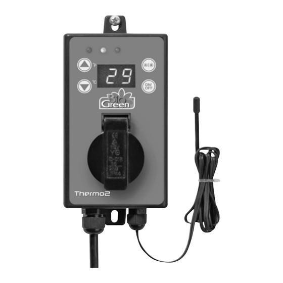
  • Page 17 1. Matériel fourni 1-Thermostat Digital Thermo 2, comprend un dispositif de suspension 2. Données techniques Type d‘appareil : Thermo 2 A limentation électrique : 110VAC ±10%, 50/60Hz C apacité de coupure max. : 1500 W C apacité de production : 15A/125VAC P lage de contrôle :...
  • Page 18 4. Conseils sur la sécurité et les risques • Seule une prise de courant 110VAC ± 10%, 50/60Hz connectée au réseau public peut être utilisée comme source de courant. Ne jamais essayer de faire fonctionner l‘appareil avec un voltage différent. •...
  • Page 19 5. Installation Assurez-vous que le voltage du secteur correspond au voltage indiqué dans le chapitre 2 (données techniques). L‘emplacement de l‘installation doit être choisi de sorte que l‘appa- reil ne soit jamais mouillé (écoulement du à la condensation, fenêtres de toit, etc.), ou ne tombe jamais dans l‘eau.
  • Page 20 6. Fonctionnement Lors de l‘installation, vérifiez que l‘appareil ou le câble de secteur n‘est pas abîmé. Assurevous aussi que le fil du senseur ne s‘est pas emmêlé car cela peut altérer son fonctionnement. Mode chaud et A llumer/Éteindre Chaud froid sur LED Froid Dès que l‘appareil est connecté...
  • Page 21 Modes opératoires Le voyant LED jaune indique si le mode chaud ou froid est actif. LED‘s Operating mode rouge jaune vert Mode „Chaud“ sélectionné/ enc. apa. apa. température théorique atteinte / Mode chaud éteint Mode „Chaud“ sélectionné/ enc. enc. apa. température théorique non atteinte / Mode chaud allumé...
  • Page 22: Représentations Et Garanties Du Fabricant

    Email: info@biogreen.de Web: www.biogreen.de Ces représentations et garanties s‘appliquent à tous les Clients (les „Clients“ et chaque, indivi- duellement, un „Client“) qui achètent des Produits (les „Produits“) fabriqués par Bio Green oHG (l‘“Entreprise) 1. Garanties et Limites : 1.1. L‘Entreprise garantie uniquement à l‘acheteur initial des Produits, pendant la période de garantie (définie ci-dessous), que les Produits ne comportent aucun défaut de matériel et de fa-...
  • Page 23: La Garantie Citée Dans La Section 1.1 Remplace Toutes Les Autres Garanties

    Produits à l‘exception de ce qui est stipulé dans la pré- sente. 1.9. All requests and notices under this Warranty shall be directed to: Bio Green USA, Inc. 350 Fifth Avenue, Suite 5220 New York, NY 10118 Phone: 1-800-941-3169 Email: info@biogreen-products.com...
  • Page 24 Bio Green Inc. 350 Fifth Avenue Suite 5220 New York, NY 10118 United States www.biogreen-products.com...