Table des Matières
Publicité
Les langues disponibles
Les langues disponibles
ServeMaster
User Manual
User Manual
User Manual
User Manual
User Manual
Benutzerhandbuch
Benutzerhandbuch
Benutzerhandbuch
Benutzerhandbuch
Benutzerhandbuch
Manuel d'Utilisateur
Manuel d'Utilisateur
Manuel d'Utilisateur
Manuel d'Utilisateur
Manuel d'Utilisateur
Manual del Usario
Manual del Usario
Manual del Usario
Manual del Usario
Manual del Usario
Manuale dell'Utente
Manuale dell'Utente
Manuale dell'Utente
Manuale dell'Utente
Manuale dell'Utente
1600 MV • 2750 MV • 3300 MV • 4600 MV
1600 MV • 2750 MV • 3300 MV • 4600 MV
1600 MV • 2750 MV • 3300 MV • 4600 MV
1600 MV • 2750 MV • 3300 MV • 4600 MV
1600 MV • 2750 MV • 3300 MV • 4600 MV
1600 HV • 2750 HV • 3300 HV • 4600 HV
1600 HV • 2750 HV • 3300 HV • 4600 HV
1600 HV • 2750 HV • 3300 HV • 4600 HV
1600 HV • 2750 HV • 3300 HV • 4600 HV
1600 HV • 2750 HV • 3300 HV • 4600 HV
Publicité
Chapitres
Table des Matières
Dépannage

Sommaire des Matières pour IBC SOLAR ServeMaster 1600 MV
- Page 1 ServeMaster User Manual User Manual User Manual User Manual User Manual Benutzerhandbuch Benutzerhandbuch Benutzerhandbuch Benutzerhandbuch Benutzerhandbuch Manuel d’Utilisateur Manuel d’Utilisateur Manuel d’Utilisateur Manuel d’Utilisateur Manuel d’Utilisateur Manual del Usario Manual del Usario Manual del Usario Manual del Usario Manual del Usario Manuale dell’Utente Manuale dell’Utente Manuale dell’Utente...
- Page 2 Choice of Language - Sprachauswahl - Choix de la langue - Selección de idioma - Scelta della lingua Page English UK Seite Deutsch Page Français Página Español Pagina Italiano L00410346-04...
-
Page 3: Table Des Matières
Contents Contents 1. Introduction Introduction 2. Function Description Definition of Operation Modes PV Configuration LEDs Display Overview Menu Section A Overview Menu Section B 3. Troubleshooting Troubleshooting Inverter Event Messages 4. Maintenance Maintenance Cleaning the Cabinet Cleaning the Heatsink L00410346-04... -
Page 4: Introduction
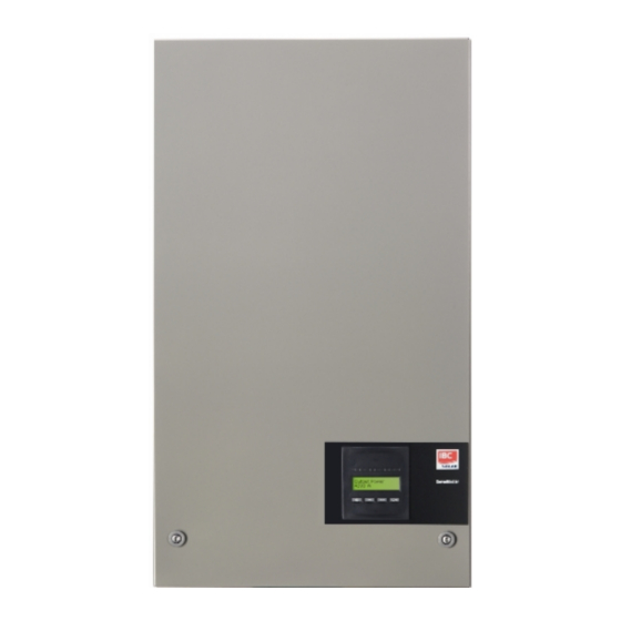
1. Introduction 1. Introduction 1.1. Introduction This manual describes IBC photovoltaic inverters. These products are among the most techno- logically advanced and efficient inverters on the market and are designed to supply the owner with reliable solar energy for many years. Illustration 1.1: ServeMaster Outdoor Inverter with Display CE marking - This certifies the conformity of the equipment with the regula- tions which apply in accordance with the directives 2004/108/EC and 2006/95/... -
Page 5: Function Description
2. Function Description 2. Function Description 2.1. Definition of Operation Modes The inverter has four modes: Standby mode: In standby mode, the inverter is ready to switch into connecting mode. As decision variable the input voltage of the PV generator is used. If the input voltage exceeds a preset nominal value, the inverter shifts from “standby”... - Page 6 2. Function Description The test works by activating the input one by one. The test takes 1-2 minutes and the inverter continues to produce energy meanwhile. In menu B the result of the test can be read in the display menu called PV configuration.
-
Page 7: Leds
2. Function Description 2.1.3. LEDs The green LED indicators show the production in percentage of the nominal inverter power rating. The leftmost green LED is always lit when the inverter is connected to the grid. While connecting to grid both the red LED and the leftmost green LED will be on. When the inverter is off grid, the red LED to the left is lit to indicate that the inverter is in standby mode. -
Page 8: Overview Menu Section B
2. Function Description 2.1.6. Overview Menu Section B The table below gives an overview of the menu structure. The two menu levels are clearly indicated by an arrow followed by a submenu. The values shown are only intended as examples of display texts. - Page 9 2. Function Description Menu Structure B- Continued Display Functions Description Total Derating Temperature. Shows the total amount of time the inverter Total drt. Temp. - Press OK to view has derated due to high temperature. ↳ Submenu DC1 Derating Temperature. Shows the amount of time the inverter has DC1 derate temp.
- Page 10 2. Function Description If an earthing fault occurs, the display will indicate this by a flash of the lit green LEDs. The display will change to “current event”, if it has not been operated in the past 10 minutes. The inverter will continue to produce energy.
-
Page 11: Troubleshooting
3. Troubleshooting 3. Troubleshooting 3.1. Troubleshooting Note: Remember that only trained and authorised personnel familiar with electrical systems and safety issues may work on inverters and electrical installations. In the following, the term 'Event' describes all events that prevent the inverter from operating properly. - Page 12 3. Troubleshooting Event text Description Fault Action in the event of a permanent fail- origin U 3.3 Internal power supply outside limits Inverter Service inverter U 5.0 Internal power supply outside limits Inverter Service inverter U 15.0 Internal power supply outside limits Inverter Service inverter U PV...
-
Page 13: Maintenance
4. Maintenance 4. Maintenance 4.1. Maintenance Normally, the ServeMaster outdoor inverters need no maintenance or calibration. It should be ensured, however, that the cooling is not obstructed. To ensure the functionality of the DC-switch (optional), all switches should be switched on and off (by turning the switch to on and off positions ten times), once a year, to clean the contacts. - Page 14 Inhaltsverzeichnis Inhaltsverzeichnis 1. Einführung Einführung 2. Funktionsbeschreibung Definition der Betriebsarten PV-Konfiguration LEDs Display Überblick Menübereich A Überblick Menübereich B 3. Fehlerbehebung Fehlerbehebung Wechselrichter – Ereignismeldungen 4. Wartung Wartung Reinigen des Schaltschranks Reinigen des Kühlkörpers L00410346-04...
-
Page 15: Einführung
1. Einführung 1. Einführung 1.1. Einführung Dieses Handbuch beschreibt die photovoltaischen Wechselrichter von IBC. Diese Produkte zählen zu den technologisch fortschrittlichsten und effizientesten Wechselrichtern auf dem Markt und ermöglichen eine verlässliche Versorgung mit Solarenergie über viele Jahre hinweg. Abbildung 1.1: ServeMaster-Wechselrichter für den Außenbereich – mit Display CE-Kennzeichnung: Diese Kennzeichnung gibt an, dass die Geräte den gel- tenden Vorschriften der Richtlinien 2004/108/EG und 2006/95/EG entspre- chen. -
Page 16: Funktionsbeschreibung
2. Funktionsbeschreibung 2. Funktionsbeschreibung 2.1. Definition der Betriebsarten Der Wechselrichter hat vier Betriebsarten: Betriebsart Standby: In der Betriebsart Standby ist der Wechselrichter bereit, auf den Anschlussmodus umzuschalten. Als Entscheidungsgröße wird die Eingangsspannung des PV-Generators herangezogen. Übersteigt die Eingangsspannung einen definierten Sollwert, wechselt der Wechselrichter aus der Betriebsart Standby in den Anschlussmodus oder leitet bei Verringerung der PV-Spannung in die Betriebsart „AUS“... -
Page 17: Pv-Konfiguration
2. Funktionsbeschreibung 2.1.2. PV-Konfiguration Bei Anschluss an das Netz führt der Wechselrichter eine automatische Prüfung der PV-Modul- verdrahtung durch. Diese Prüfung bestimmt die Verdrahtungskonfiguration der Module. Es wird ermittelt, ob die Module in Individual-Modus Konfiguration oder Parallele String-Konfiguration an- geschlossen sind, und der Wechselrichter wird automatisch entsprechend konfiguriert. Die Prüfung aktiviert nacheinander jeden Eingang. -
Page 18: Leds
2. Funktionsbeschreibung *) „PARALLEL 1-2“ ist nur für den Wechselrichter ServeMaster 2750 / 3300 zulässig. „PARALLEL 1-2“, „PARALLEL 1-3“ und „PARALLEL 2-3“ ist für den Wechselrichter ServeMaster 4600 nicht zulässig. 2.1.3. LEDs Die grünen LED-Anzeigen geben die Produktion in Prozent der Nennleistung des Wechselrichters Die ganz links befindliche grüne LED leuchtet immer auf, wenn der Wechselrichter mit dem Netz verbunden ist. -
Page 19: Überblick Menübereich A
2. Funktionsbeschreibung 2.1.5. Überblick Menübereich A Die nachfolgende Tabelle bietet einen Überblick der Menüstruktur. Die angegebenen Werte dienen nur als Beispiel für die Displaytexte. Der Displaytext (siehe erste Spalte „Displayfunktionen“) wird auf zwei Zeilen à 16 Zeichen angezeigt. Der Zeilenumbruch ist durch das Symbol | gekennzeichnet. Menüstruktur A Displayfunktionen Beschreibung... -
Page 20: Überblick Menübereich B
2. Funktionsbeschreibung 2.1.6. Überblick Menübereich B Die nachfolgende Tabelle bietet einen Überblick der Menüstruktur. Die beiden Menüebenen wer- den durch einen Pfeil gekennzeichnet, dem ein Untermenü folgt. Die angegebenen Werte dienen nur als Beispiel für die Displaytexte. Der Displaytext (siehe erste Spalte „Displayfunktionen“) wird auf zwei Zeilen à 16 Zeichen ange- zeigt. - Page 21 2. Funktionsbeschreibung Menüstruktur B – Fortsetzung Displayfunktionen Beschreibung Temperaturminderung insgesamt. Zeigt den Gesamtwert des Zeitraums an, Temp mind gesamt | OK drücken über den der Wechselrichter aufgrund von hohen Temperaturen gedrosselt wurde. ↳ Untermenü Temperaturminderung DC1. Zeigt den Zeitraum an, über den der Wechselrich- DC1 Temp.
- Page 22 2. Funktionsbeschreibung Wurde der Wechselrichter aufgrund eines Fehlers vom Netz getrennt, beginnt die rote LED zu blinken, und die Anzeige wechselt automatisch in das Menü B, in dem das Ereignis angezeigt wird. Tritt ein Erdungsfehler auf, wird dieser am Display durch Blinken der grünen LEDs angezeigt. Die Anzeige wechselt zu „Aktuelles Ereignis“, wenn in den letzten zehn Minuten keine Aktualisierung erfolgt ist.
-
Page 23: Fehlerbehebung
3. Fehlerbehebung 3. Fehlerbehebung 3.1. Fehlerbehebung Anmerkung: Beachten Sie, dass alle Arbeiten an Wechselrichtern und elektrischen Installationen nur von geschultem und autorisiertem, mit elektrischen Anlagen und Sicherheitsfragen vertrautem Per- sonal vorgenommen werden dürfen. Im Folgenden beschreibt der Ausdruck „Ereignis“ alle Ereignisse, die den Wechselrichter daran hindern, ordnungsgemäß... - Page 24 3. Fehlerbehebung Ereignistext Beschreibung Fehler- Maßnahme bei einem dauerhaften Feh- ursache U 3,3 Interne Stromversorgung außerhalb Wechsel- Den Wechselrichter warten der Grenzwerte richter U 5,0 Interne Stromversorgung außerhalb Wechsel- Den Wechselrichter warten der Grenzwerte richter U 15,0 Interne Stromversorgung außerhalb Wechsel- Den Wechselrichter warten der Grenzwerte...
-
Page 25: Wartung
4. Wartung 4. Wartung 4.1. Wartung Die ServeMaster Wechselrichter für den Außenbereich erfordern im Normalfall keine Wartung oder Kalibrierung. Es ist nur auf eine unbehinderte Kühlung zu achten. Um die Funktionalität des DC-Schalters (optional) sicherzustellen, müssen alle Schalter einmal pro Jahr aus- und eingeschaltet werden (hierzu den Schalter zehnmal ein- und ausschalten), um die Kontakte zu reinigen. - Page 26 Table des matières Table des matières 1. Introduction Introduction 2. Description de fonction Définition des modes de fonctionnement Configuration PV Écran Section A du menu de présentation Section B du menu de présentation 3. Dépannage Dépannage Messages d'événements de l'onduleur 4.
-
Page 27: Introduction
1. Introduction 1. Introduction 1.1. Introduction Ce manuel décrit des onduleurs photovoltaïques IBC. Ces produits comptent parmi les onduleurs les plus efficaces et sophistiqués du marché. Leur conception assure pendant de longues années à leur propriétaire une alimentation en énergie solaire fiable. Illustration 1.1: ServeMaster Onduleur extérieur avec écran Marquage CE : Ce marquage certifie la conformité... -
Page 28: Description De Fonction
2. Description de fonction 2. Description de fonction 2.1. Définition des modes de fonctionnement L'onduleur dispose de quatre modes : Mode Veille : En mode Veille, l'onduleur est prêt à basculer en mode Connexion. La tension d'entrée du géné- rateur PV constitue la variable déterminante. Si la tension d'entrée excède une valeur nominale préréglée, l'onduleur passe du mode Veille au mode Connexion ou continue à... -
Page 29: Configuration Pv
2. Description de fonction 2.1.2. Configuration PV Lors du raccordement au réseau, un test automatique du câblage du module PV est effectué par l'onduleur. Ce test est réalisé pour déterminer la configuration de câblage des modules. Il détecte si les modules sont connectés dans une configuration de branches individuelles ou parallèles, et l'onduleur est automatiquement paramétré... -
Page 30: Led
2. Description de fonction Le champ relatif à l'état peut préciser les points suivants : Affichage Description DISPO Le test de la configuration PV n'a pas encore été exécuté. S'affiche avant le rac- cordement de l'onduleur au réseau. Le test de la configuration PV est désactivé. Applicable aux onduleurs ServeMaster 1650 et aux onduleurs où... -
Page 31: Section A Du Menu De Présentation
2. Description de fonction Les paramètres affichés à l'écran font référen- ce à des tensions et courants mesurés en in- terne. Les paramètres indiqués peuvent va- rier. Les informations d'affichage sont organisées dans une structure de menu divisée en deux sections : A et B. -
Page 32: Section B Du Menu De Présentation
2. Description de fonction 2.1.6. Section B du menu de présentation Le tableau ci-dessous fournit un aperçu de la structure de menu. Les deux niveaux de menu sont clairement indiqués par une flèche suivie d'un sous-menu. Les valeurs indiquées ne sont données qu'à... - Page 33 2. Description de fonction Structure de menu B - suite Fonctions d'affichage Description Dégradation température totale. Affiche le temps total pendant lequel l'on- Réduc temp. tot | App. OK pour voir duleur a fonctionné en réduction en raison d'une température élevée. ↳...
- Page 34 2. Description de fonction Si l'onduleur est déconnecté du réseau suite à une panne, la LED rouge commence à clignoter et l'écran bascule automatiquement sur le menu B qui affiche l'événement. Si un défaut de mise à la terre survient, l'écran le mentionnera par un clignotement de la LED verte allumée.
-
Page 35: Dépannage
3. Dépannage 3. Dépannage 3.1. Dépannage Remarque: Ne pas oublier que seul du personnel formé, autorisé et expérimenté en matière de systèmes électriques et de sécurité est habilité à intervenir sur des onduleurs et des installations élec- triques. Dans les chapitres suivants, le terme « Événement » décrit tous les événements qui empêchent le bon fonctionnement de l'onduleur. - Page 36 3. Dépannage Message de l'événe- Description Origine Action en cas de panne permanente ment du défaut U 3.3 Alimentation électrique interne hors li- Onduleur Intervenir sur l'onduleur mites U 5.0 Alimentation électrique interne hors li- Onduleur Intervenir sur l'onduleur mites U 15.0 Alimentation électrique interne hors li- Onduleur...
-
Page 37: Maintenance
4. Maintenance 4. Maintenance 4.1. Maintenance Normalement, les onduleurs d'extérieur ServeMaster ne nécessitent ni maintenance, ni étalonna- ge. Cependant, s'assurer que le système de refroidissement n'est pas obstrué. Pour assurer le bon fonctionnement de l'interrupteur CC (optionnel), tous les interrupteurs doivent être allumés puis éteints (en mettant l'interrupteur en position allumée puis éteinte dix fois) une fois par an pour nettoyer les contacts. - Page 38 Índice Índice 1. Introducción Introducción 2. Descripción de las funciones Definición de los modos de funcionamiento Configuración FV Indicadores LED Display Información general sobre la sección A del menú Información general sobre la sección B del menú 3. Resolución de problemas Resolución de problemas Mensajes de incidencias en el inversor 4.
-
Page 39: Introducción
1. Introducción 1. Introducción 1.1. Introducción Este manual describe los inversores fotovoltaicos IBC. Estos productos se encuentran entre los inversores más avanzados tecnológicamente del mercado y están diseñados para proporcionar al propietario energía solar fiable durante muchos años. Ilustración 1.1: ServeMaster Inversor exterior con display Marcado CE: certifica la conformidad del equipo con la normativa aplicable según lo establecido en las directivas 2004/108/CE y 2006/95/CE. -
Page 40: Descripción De Las Funciones
2. Descripción de las funciones 2. Descripción de las funciones 2.1. Definición de los modos de funcionamiento El inversor presenta cuatro modos de funcionamiento: Modo de espera: En el modo de espera, el inversor está listo para pasar al modo de conexión. Aunque puede cambiarse, el inversor utiliza por defecto el voltaje de entrada del generador FV. -
Page 41: Configuración Fv
2. Descripción de las funciones 2.1.2. Configuración FV Después de conectarse a la red, el inversor efectúa una prueba automática del cableado del mó- dulo FV. Esta prueba se realiza para determinar la configuración del cableado de los módulos. Sirve para determinar si los módulos están conectados en configuración de cadena individual o en paralelo y si el inversor se ha configurado de forma automática como corresponde. -
Page 42: Indicadores Led
2. Descripción de las funciones *) El «PARALLEL 1-2» solo está permitido para el inversorServeMaster 2750 / 3300. Los paralelos «PARALLEL 1-2», «PARALLEL 1-3» y «PARALLEL 2-3» no están permitidos para el inversor ServeMaster 4600. 2.1.3. Indicadores LED Los indicadores LED de color verde muestran la producción como un porcentaje del nivel de ener- gía nominal del inversor. -
Page 43: Información General Sobre La Sección A Del Menú
2. Descripción de las funciones 2.1.5. Información general sobre la sección A del menú En la tabla que aparece a continuación, se presenta de forma breve la estructura del menú. Los valores se presentan únicamente a modo de ejemplo de los textos del display. El texto del display (que se muestra en la primera columna «Funciones del display») se divide en dos líneas, con un máximo de 16 caracteres por línea. -
Page 44: Información General Sobre La Sección B Del Menú
2. Descripción de las funciones 2.1.6. Información general sobre la sección B del menú En la tabla que aparece a continuación, se presenta de forma breve la estructura del menú. Los dos niveles del menú quedan claramente diferenciados por una flecha seguida de un submenú. Los valores se presentan únicamente a modo de ejemplo de los textos del display. - Page 45 2. Descripción de las funciones Estructura del menú B: continuación Funciones del display Descripción Reducción de potencia total por temperatura. Muestra el tiempo total du- Desgrad. temp tot - Pres OK para ver rante el cual el inversor ha reducido su potencia debido a las altas tem- peraturas.
- Page 46 2. Descripción de las funciones la prueba de configuración PV, el display pasa temporalmente al menú B para mostrar el estado de la prueba de configuración PV. Si el inversor se desconecta de la red debido a un fallo, el indicador LED rojo empezará a parpadear y el display pasará...
-
Page 47: Resolución De Problemas
3. Resolución de problemas 3. Resolución de problemas 3.1. Resolución de problemas Nota: Recuerde que los inversores y las instalaciones eléctricas solo deben ser manipulados por per- sonal autorizado, debidamente capacitado y familiarizado con los sistemas eléctricos y las cuestiones de seguridad. En lo sucesivo, el término «incidencia»... - Page 48 3. Resolución de problemas Texto de la inciden- Descripción Origen del Medidas necesarias en caso de fallo fallo permanente U 3.3 Suministro de energía interna fuera de Inversor Repare el inversor los límites permitidos U 5.0 Suministro de energía interna fuera de Inversor Repare el inversor los límites permitidos...
-
Page 49: Mantenimiento
4. Mantenimiento 4. Mantenimiento 4.1. Mantenimiento Normalmente, los inversores para exteriores ServeMaster no necesitan mantenimiento ni calibra- ción. Sin embargo, es importante comprobar que no haya nada que obstruya el sistema de refri- geración. Para garantizar la funcionalidad del interruptor de CC (opcional), deberían activarse y desactivarse todos los interruptores (cambiando el interruptor a la posición de activación y desactivación diez veces) una vez al año, para limpiar los contactos. - Page 50 Sommario Sommario 1. Introduzione Introduzione 2. Descrizione delle Funzionalità Definizione delle modalità di funzionamento Configurazione FV Display Panoramica Sezione Menu A Panoramica sulla Sezione Menu B 3. Risoluzione dei problemi Risoluzione dei problemi Messaggi di evento dell’inverter 4. Manutenzione Manutenzione Pulizia del Cabinet Pulizia del dissipatore di calore L00410346-04...
-
Page 51: Introduzione
1. Introduzione 1. Introduzione 1.1. Introduzione Questo manuale offre una descrizione degli inverter fotovoltaici IBC. Questi prodotti sono consi- derati gli inverter più efficienti e tecnologicamente avanzati presenti sul mercato e sono progettati per fornire all'utente un supporto affidabile di energia solare che duri molti anni. Disegno 1.1: ServeMaster Inverter outdoor con display Marcatura CE –... -
Page 52: Descrizione Delle Funzionalità
2. Descrizione delle Funzionalità 2. Descrizione delle Funzionalità 2.1. Definizione delle modalità di funzionamento L’inverter ha quattro modalità di funzionamento: Modalità standby: Nella modalità di attesa, l'inverter è pronto a commutare alla modalità di connessione. Come va- riabile decisionale si utilizza la tensione di ingresso del generatore FV. Se la tensione di ingresso supera un valore nominale preimpostato, l'inverter passa da “attesa”... - Page 53 2. Descrizione delle Funzionalità Il test funziona attivando un ingresso per volta. Il tempo necessario per il test è di 1-2 minuti durante i quali l'inverter continua a produrre energia. Nei menu B è possibile leggere il risultato del test nel menu del display denominato Configuraz. FV. Una volta completato il test, il display visualizza automaticamente la configurazione FV, ma solo se i pulsanti del display non sono stati utilizzati negli ultimi 3 minuti.
-
Page 54: Led
2. Descrizione delle Funzionalità 2.1.3. LED Gli indicatori LED verdi mostrano la produzione come percentuale della potenza nominale dell'in- verter. Il LED verde più a sinistra è sempre illuminato quando l'inverter è connesso alla rete. Durante la connessione alla rete di distribuzione sia il LED rosso che il LED verde più a sinistra saranno accesi. Quando l'inverter non è... -
Page 55: Panoramica Sezione Menu A
2. Descrizione delle Funzionalità 2.1.5. Panoramica Sezione Menu A La tabella in basso offre una panoramica della struttura del menu. I valori indicati devono essere intesi unicamente come esempi di testi visualizzati. Il testo display (visualizzato nella prima co- lonna Funzioni display) è suddiviso su 2 righe con 16 caratteri disponibili per riga. La divisione della riga è... -
Page 56: Panoramica Sulla Sezione Menu B
2. Descrizione delle Funzionalità 2.1.6. Panoramica sulla Sezione Menu B La tabella in basso offre una panoramica della struttura del menu. I due livelli di menu sono chiaramente indicati da una freccia seguita da un sottomenu. I valori indicati devono essere intesi unicamente come esempi di testi visualizzati. - Page 57 2. Descrizione delle Funzionalità Struttura Menu B - Prosegue Funzioni visualizzate Descrizione: Degradazione totale temperatura. Mostra la quantità totale di tempo nel Degrada. tmp tot | Prem. OK p. vedere quale l'inverter è stato degradato a causa dell'alta temperatura. ↳ Sottomenu Degradazione temperatura CC1.
- Page 58 2. Descrizione delle Funzionalità Se si verifica un guasto di terra, il display lo indicherà tramite un lampeggiamento dei LED verdi accesi. Il display passerà a "evento attuale" se non è stato usato negli ultimi 10 minuti. L'inverter continuerà a produrre energia. Se si verifica un guasto di terra, ciò non indica un errore dell'inverter ed è...
-
Page 59: Risoluzione Dei Problemi
3. Risoluzione dei problemi 3. Risoluzione dei problemi 3.1. Risoluzione dei problemi Nota: È necessario tenere a mente che solo il personale addestrato e autorizzato, competente su sistemi elettrici e questioni legate alla sicurezza, può lavorare sugli inverter e le installazioni elettriche. - Page 60 3. Risoluzione dei problemi Testo evento Descrizione: Origine Azione in caso di guasto permanente guasto U 3.3 Alimentazione elettrica interna oltre i li- Inverter Revisionare l'inverter miti U 5.0 Alimentazione elettrica interna oltre i li- Inverter Revisionare l'inverter miti U 15.0 Alimentazione elettrica interna oltre i li- Inverter Revisionare l'inverter...
-
Page 61: Manutenzione
4. Manutenzione 4. Manutenzione 4.1. Manutenzione Di norma gli inverter ServeMaster non hanno necessità di manutenzione o calibrazione. Tuttavia è necessario assicurare che il raffreddamento non sia ostruito. Per assicurare la funzionalità dell'interruttore di sconnessione CC (opzionale), tutti gli interruttori dovrebbero essere accessi e spenti (commutando l'interruttore per dieci volte su On e Off) una volta all'anno al fine di pulire i contatti. - Page 62 IBC SOLAR AG IBC SOLAR AG IBC SOLAR AG IBC SOLAR AG IBC SOLAR AG Am Hochgericht 10 96231 Bad Staffelstein *C00410459* Fon: +49 9573 9224-0 Fax: +49 9573 9224-111 www.ibc-solar.com C00410459 Danfoss can accept no responsibility for possible errors in catalogues, brochures and other printed material. Danfoss reserves the right to alter its products without notice. This also applies to products already on order provided that such alterations can be made without subsequential changes being necessary in specifications already agreed.