Table des Matières
Publicité
Liens rapides
Publicité
Table des Matières
Dépannage

Manuels Connexes pour John Bean B 340


Sommaire des Matières pour John Bean B 340
- Page 1 Operator’s Manual Manuel d’Utilisation Operator’s Manual Manuel d’Utilisation Manuel d’Utilisation Manuel d’Utilisation anuel d’Utilisation Manuel d’Utilisation Manuel d’Utilisation Manuel d’Utilisation Manuel d’Utilisation Manuel d’Utilisation d’Utilisation d’Utilisation anual do Operador Manual do Operador Manual do Operador Manual do Operador B 340...
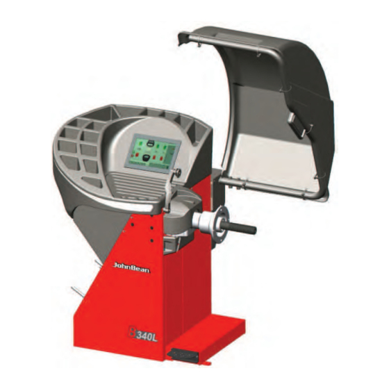
- Page 2 FAMILY NAME MODELS DESCRIPTION of the MACHINE (basic features) Sonar system. B340S Sonar system / Laser pointer system. B 340 B340L Sonar system / Laser pointer system / Power clamp system. B340P EC DECLARATION (Original document contained in Spare Parts Booklet) DÉCLARATION CE...
- Page 3 Conteúdos em SP Содержится в каталоге запчастей EC DECLARATION DICHIARAZIONE CE EG-KONFORMITÄTSERKLÄRUNG DECLARACIÓN CE DECLARATION CE DECLARAÇÃO CE ДЕКЛАРАЦИЯ ЕС Wiring Diagram Schema Elettrico Schaltplan SAVE THESE INSTRUCTIONS Esquema Eléctrico Schéma électrique Esquema Elétrico Схема электрических соединений John Bean B340...
-
Page 4: Table Des Matières
WARRANTY TERMS AND LIABILITY UPDATES REPORT LIMITATIONS While the authors have taken care in the preparation Release:______ ________ Sept 2019 of this manual, nothing contained herein: PCN:____________________ 19G0166 modifies or alters in any way the standard Accessories section: terms and conditions of the purchase, lease or Standard Caliper EAA0247G21A for rim width;... - Page 5 APPLICATION DE LA GARANTIE ET VENCIMIENTO DE LA GARANTÍA Y LIMITATIONS DE RESPONSABILITÉ LIMITACIONES DE RESPONSABILIDAD Bien que les auteurs aient accordé la plus grande A pesar de que los autores han prestado la máxima attention à la rédaction du présent manuel, aucun atención al redactar este manual, se señala que el élément fi...
-
Page 6: Safety
Safety 1.0 Safety The safety precautions must be completely understood and observed by every operator. The Operator’s Manual will contain specifi c warnings and cautions when dangerous situations may be encountered during the procedures described. Important safety precautions relevant to the unit are described in the Safety Booklet, refer to Figure 1-1. -
Page 7: Sécurité
Sécurité Seguridad Sécurité Seguridad Tout opérateur doit avoir une parfaite connaissance des Todos los operadores deberán comprender las consignes de sécurité et il est tenu de les respecter. Quand precauciones de seguridad y respetarlas. El Manual les opérations décrites peuvent créer des situations del Operador contiene advertencias específi... -
Page 8: Specifi Cations
Specifi cations 2.0 Specifi cations " " $ $ # $ $ " " & $ & '" # & '# " & $ " " &'(!)( &(* " &'(!)( &(* $( & $( & ( & ( & ( & ( &... -
Page 9: Spécifi Cations
Specifi cations Especifi caciones Spécifi cations Especifi caciones % & ()*+,* (*- ()*+,* (*- ! " # " & ' " / " & *& & 1 1 2 ' , , . '+ 1 1 2 , , . &... -
Page 10: Introduction
Introduction 3.0 Introduction This wheel balancer combines advanced, high- performance technology, robustness and reliability with very simple, user-friendly operation. The slow rotation speed of the wheel ensures a completely safe use. The colour monitor displays set data, operating modes, values measured, symbols and text of the operator guide. -
Page 11: Introduction
Introduction Introducción 3.0 Introduction 3.0 Introducción Cette équilibreuse vous offre une technologie avancée Esta equilibradora de ruedas combina una tecnología de haute performance, solidité et fiabilité et son avanzada y de alto rendimiento, robustez y confi anza, fonctionnement est très simple et convivial. con un funcionamiento sencillo y fácil de manejar. -
Page 12: Accessories
Accessories Accessories Refer to Figure 3-3. Quick Clamp The standard accessories are: Quick Nut EAA0263G66A Power Clamp Power Clamp Nut EAM0086G86A Plastic sleeve EAM0058D69A Drum Cushion EAC0058D15A Wheel pressing Drum EAC0058D07A Pressure ring EAC0058D08A Cone, 87-137 mm / 3.4”-5.4” EAN0003J69A Large cone EAM0005D25A Cone, 96-114 mm / 3.8”-4.5”... -
Page 13: Accessoires
Accessoires Accessorios Accessoires Accesorios Se reporter à la Fig. 3-3. Consultar la Figura 3-3. Les accessoires standard sont : Los accesorios normales son: Écrou à serrage rapide Tuerca rápida EAA0263G66A EAA0263G66A Embout de blocage Power Clamp Tuerca Power Clamp EAM0086G86A EAM0086G86A Manchon en plastique EAM0058D69A... -
Page 14: Layout
Layout 4.0 Layout Refer to Figure 4-1. Functional description of the unit: 1. Touch screen Refer to Chapter 4.1. 2. Input panel Refer to Chapter 4.1.2 3a Gauge arm 3b. External Detector - Sonar 4. Flange 5. Stub shaft 6. Weight compartments 7. -
Page 15: Disposition
Disposition Disposición 4.0 Disposition Disposición Se reporter à la Fig. 4-1. Consultar la Figura 4-1. Description fonctionnelle de la machine : Descripción funcional de la unidad: 1. Affi cheur tactile 1. Pantalla táctil Se reporter au Chapitre 4.1 Consultar Capítulo 4.1. 2. - Page 16 Layout 4.1 The screen Fig. 4-3 Screen with display fi elds. Display fi eld. Information fi eld. Commands Field (Key pad). The screen shows the set data, helpful information, all measured data and possible Error codes. Description of display fi elds Each fi...
- Page 17 Disposition Disposición 4.1 Écran Pantalla Fig. 4-3 Écran avec zones d’affi chage. Fig. 4-3 Zonas de visualización de la pantalla. Zone d’affi chage. Campo de visualización. Zone d’informations. Campo de información.. Zone de commandes (Clavier). Campo de mandos (Teclado). Sur l’écran sont affi chés les paramètres, les textes En la pantalla se visualizan los datos introducidos, las d’aide, toutes les valeurs mesurées et les messages informaciones útiles para el operario, todos los valores...
- Page 18 Layout 4.1.1 Screen pages / Menu Types of Menu Fields The Display fi eld shows the main Operating Screen Pages: Fig. 4-5 INTRO SCREEN Basic screen / Main menu. Available once the start-up is completed. Note: From this screen page, simply removing the arm causes an automatic switch to the “RIM DATA ENTRY”...
-
Page 19: Les Pages-Écrans / Menu
Disposition Disposición 4.1.1 Les pages-écrans / Menu 4.1.1 Las páginas visibles / Menú Types de Zones Menu Tipos de campos de menú La zone Affi chage donne accès aux principales Pages- El campo de visualización muestra las siguientes écrans opérationnelles : Pantallas operativas: Fig. - Page 20 Layout Fig. 4-9 SETTING Settings Screen. You may access it with the Key (1) Even though the machine presents the most common functions already selected, the operator can customise various display specifi cations and process modes. This screen lets the operator customise all the operating settings to his/her specifi...
- Page 21 Disposition Disposición Fig. 4-9 Fig. 4-9 SETTING SETTING Page-écran Réglages. Pantalla Confi guraciones. Il est possible d’accéder avec la touche (1) . Es posible acceder con la Tecla (1). Même si le véhicule présente déjà les éléments d’usage Aunque la máquina ya presenta seleccionados los plus communs sélectionnés, l’opérateur est en mesure elementos de uso más común, el operador puede d’adapter différentes caractéristiques d’affi...
- Page 22 Layout Fig. 4-13 OPTIMIZATION Optimisation / weight Minimisation screen page. You may access it with the Key (1) after a measuring run. 4-13 Fig. 4-14 OP. 1 Optimisation screen page. You may access the optimisation/minimisation screen by pressing Key (1). 4-14 Fig.
- Page 23 Disposition Disposición Fig. 4-13 Fig. 4-13 OPTIMIZATION OPTIMIZATION Page-écran Optimisation/Minimisation. Pantalla Optimización/Minimización. Il est possible d’accéder avec la touche (1) à la suite Es posible acceder con la Tecla (1) tras el lanzamiento de la lancée de mesure. de medición. Fig.
-
Page 24: Command Keys
Layout 4.1.2 Fundamental commands STOP Figure 4.-14 When the Stop Button is pressed, the machine stops all automatic movements. 4.1.2.1 Command Keys 4-14 The Menu Keys are in the Commands Field. Therefore, depending on the position in the program, the many Operating Screen Pages will in each case show the Command keys needed for the functions available. -
Page 25: Commandes De Base
Disposition Disposición 4.1.2 Commandes de base 4.1.2 Comandos Básicos ARRÊT STOP Figure 4-14 Figura 4-14 À la pression du bouton d’arrêt, la machine effectue Al presionar el botón de Stop la máquina detiene todos l’arrêt de tous les mouvements automatiques. los movimientos automáticos. - Page 26 Layout START key – Start the measuring run. Press to start wheel rotation, with the wheel guard down. STOP key – Immediately brakes the measuring run and any other automatic movement in progress, for example, wheel clamping and the Lifter (if present). 3b PROFILES key –...
- Page 27 Disposition Disposición Touche START Tecla START – Initialiser la lancée de mesure. – Iniciar lanzamiento de medición. Presser pour lancer la rotation de la roue, après Púlsela para iniciar la rotación de la rueda, con la avoir abaissé le carter de roue. protección de la misma hacia abajo.
- Page 28 Layout EASY ALU TOGGLE key – With the “Easy Alu Toggle” key you can change the Alu mode proposed by the machine. HOME Key – Returns to the home page INTRO SCREEN. OPT/MIN Key – Starts the Optimisation / Minimisation program. SPLIT Key –...
- Page 29 Disposition Disposición Touche EASY ALU TOGGLE Tecla EASY ALU TOGGLE – Avec le bouton “Easy Alu Toggle” vous pouvez – Con el botón “Easy Alu Toggle” se puede modifi car changer le mode Alu suggéré par la machine. el modo Alu sugerido por la máquina. Touche HOME Tecla HOME –...
- Page 30 Layout RESTART OPT/MIN key – If the optimisation/minimisation run is to be started after an interruption, press the key (1d, Fig. 4-15d). MINIMISATION key – Starts the Minimisation program. CONFIRMATION / CONTINUE key – Confi rms the action or acquires the selection and continues.
- Page 31 Disposition Disposición Touche RESTART OPT/MIN Tecla RESTART OPT/MIN – Si après l’interruption d’un cycle d’optimisation/ – Si es preciso reanudar la optimización/minimización minimisation, celui-ci doit être redémarré, appuyer sur de peso después de haber interrumpido el programa, la touche (1d, Fig. 4-15d). basta con pulsar la tecla (1d, Fig.
- Page 32 Layout MULTIMEDIA Key – Allows accessing the Multimedia screen. CUSTOMER DATA ENTRY Key – Allows accessing the Customer Data Entry screen. ADD BEFORE BALANCING Key – Allows adding to the report the measurement run data, i.e. the one carried out before the application of balance weights.
- Page 33 Disposition Disposición Touche MULTIMÉDIA Tecla MULTIMEDIA – Permet d’accéder à l’écran Multimédia. – Permite acceder a la pantalla Multimedia. Touche SAISIE DES DONNÉES DU Tecla INTRODUCCIÓN DATOS CLIENTE CLIENT – Permite acceder a la pantalla Customer Data Entry. – Permet d’accéder à l’écran Customer Data Entry. Tecla AÑADIR ANTES DEL EQUILIBRADO Touche AJOUT AVANT L’ÉQUILIBRAGE –...
-
Page 34: Pictographs - Symbols
Layout Pictographs – Symbols Pictographs • Pictogrammes • Pictogramas Pictographs and symbols are displayed on the monitor in all fi elds: in Display, Information, and Menu fi elds. P1 Wheel type 1 - standard - normal size in inches or millimetres. -
Page 35: Symboles - Pictogrammes
Disposition Disposición Symboles - Pictogrammes Símbolos y Pictogramas Sur l’écran, des pictogrammes sont affi chés dans En la pantalla se visualizan símbolos y pictogramas en toutes les zones d’affichage ; dans les zones todas las zonas: en los campos de información y de d’information, les zones de menu et dans la zone menú, así... - Page 36 Layout Pictographs • Pictogrammes • Pictogramas P14 Compensation run carried out P15 Start measuring run by pressing the START key or by lowering the wheel guard. P16 Set the Calibration weight P17 Use a chalk to make a mark on left tyre side. P18 Use a chalk to make a mark on right tyre side.
- Page 37 Disposition Disposición P14 Lancée de compensation effectuée. P14 Lanzamiento de compensación realizado. P15 Effectuer une lancée de mesure en appuyant sur P15 Iniciar el lanzamiento pulsando la tecla START o la touche START ou bajando la protección de la rueda. en baissant le carter de roue.
-
Page 38: Laser Pointer
Layout Stop brake Fig. 4-16 Wheel stop brake pedal Press the pedal to brake the wheel holder chuck to make clamping nut locking or unlocking easier. The wheel is retained in the correction position for correct fi tting of the balance weights. Warning: This brake is designed only to facilitate orientation of the wheel and must not be used for braking the... - Page 39 Disposition Disposición Pédale de blocage Freno de paro Fig. 4-16 Pédale de blocage roue Figura 4-16 Pedal de freno de parada rueda L’arbre principal est bloqué quand la pédale est Pisando el pedal se bloquea el mandril. Esto facilita actionnée. Cela permet de serrer ou de desserrer apretar o afl...
-
Page 40: Help Information
Layout Help information Help information explains the current action and, in the case of an error code, also provides hints for remedy. Display help information — Press the HELP key (Fig. 4-15, Pos.). 3). 4-15 The fi rst screen with help information appears, e. g. to the screen RIM DATA ENTRY (Fig. - Page 41 Disposition Disposición Textes d’aide Textos de ayuda Les textes d’aide expliquent l’opération en cours et Las informaciones de ayuda explican la situación donnent des consignes en cas de messages d’erreur operativa y, aparecen mensajes de error, facilita pour pouvoir trouver un remède. indicaciones para la correspondiente eliminación.
-
Page 42: Stop Button
Operation Stop button Refer to (Figure 4-14). To perform an immediate stop: • Press the Electromechanical stop button; The electronic brake is activated to immediately stop wheel shaft rotation, as well as any other balancer automatic movement. In the event of a stop due to an unexpected action by the unit, reconstruct the steps taken: Did the operator make an error or omit to do something? -
Page 43: Bouton D'arrêt
Utilisation Operaciónes Bouton d’arrêt Botón de parada Se reporter à la (Figure 4-14). Consulte la (Figura 4-14).. Pour effectuer un arrêt immédiat : Para efectuar una parada inmediata: • Appuyer sur le bouton d’arrêt Électromécanique ; • Pulse el botón de parada electromecánica; Le frein électronique intervient pour l’arrêt immédiat El freno eléctrico se activa y detiene de manera de la rotation de l’arbre porte-roue, ainsi que tout... -
Page 44: Operation
Operation 5.0 Operation This chapter describes how to operate the unit in order to balance a wheel. First it describes standard balancing operations. From chapter 5.10 on, special functions will be described. Be familiar with: possible hazards, ( unit, ( Clamping a wheel Figure 5-1 illustrates clamping a conventional car wheel using a clamping adaptor on the centre bore. -
Page 45: Utilisation
Utilisation Operaciónes 5.0 Utilisation 5.0 Funcionamiento Ce chapitre décrit l’utilisation de la machine pour En este capítulo se describe cómo efectuar un équilibrer une roue. equilibrado de una rueda. Les opérations d’équilibrage standard sont d’abord Primero se describe el funcionamiento normal de décrites. -
Page 46: Clamping / Unclamping The Wheel
Operation 5.2 POWER CLAMP (if present) Fig. 5-3 The main shaft lock pedal has two functions PEDAL DOWN: Stopping rotation PEDAL UP: POWER CLAMP lock The pedal also controls the POWER CLAMP, for clamping the wheel on the balancer. Power Clamp with jaws fully open. Power Clamp with jaws fully closed. -
Page 47: Serrage/Desserrage De La Roue
Utilisation Operaciónes 5.2 POWER CLAMP (si présent) 5.2 POWER CLAMP (si se dispone) Fig. 5-3 Fig. 5-3 La pédale de blocage de l’arbre principal a une double El pedal de bloqueo del árbol principal tiene doble fonction : función: PÉDALE APPUYÉE : PEDAL ABAJO: Blocage de la rotation Bloqueo de la rotación... - Page 48 Operation • Press the clamping sleeve and clamping tool fi rmly against the wheel and lift the pedal (Fig. 5-7a). • Check for proper clamping prior to the measuring run. Warnings: If the pedal is actuated once again during the clamping process, clamping is interrupted and the clamping jaws return to unclamped position.
-
Page 49: Desserrage De Roue
Utilisation Operaciónes • Presser la douille et le moyen de serrage fortement • Apretar fi rmemente el manguito tensor con el útil contre la roue et soulever la pédale (Fig. 5-7a). de fi jación seleccionado contra la rueda y levantar el pedal (Fig. -
Page 50: Preparation
Operation Preparation • The operator should be familiar with the warnings and cautions • The operator should be qualifi ed to work with the machine. • Alwaysensure that the wheel guard is lifted and the gauge arm is in its home position (fully retracted). 5.4.1 Power up •... - Page 51 Utilisation Operaciónes Préparation Preparación • L’opérateur doit se familiariser avec les • El operador debe estar familiarizado con las avertissements et les mesures de sécurité. advertencias y precauciones. • L’opérateur doit être formé pour travailler avec la • El operador debe estar califi cado para trabajar con machine.
-
Page 52: Status At Switching On
Operation 5.4.2 Status at switching on The electronics is factory programmed so that upon The electronic unit is factory-adjusted to the following machine start-up the following operating modes are modes of operation, which are available after switching pre-set: – vehicle type 1 (car wheel with nominal –... -
Page 53: État Au Démarrage
Utilisation Operaciónes 5.4.2 Estado durante la puesta en marcha 5.4.2 État au démarrage L’unité électronique est programmée par le fabricant de La unidad electrónica está programada por el La unidad electrónica está programada por el L’unité électronique est programmée par le fabricant de fabricante de manera que, después de la puesta en fabricante de manera que, después de la puesta en façon à... -
Page 54: Shutting Down
Operation 5.4.4 Shutting down Always shut down properly when work is complete: • Remove the wheel from the balancer. • Remove the cones from the stub shaft. Check the surfaces (internal and external) of the cones for damage. The conditions of the cone are very important for a good balance quality. -
Page 55: Retrait De La Roue
Utilisation Operaciónes 5.4.4 Arrêt 5.4.4 Apagado À la fi n du travail compléter toujours les opérations de Apague siempre adecuadamente al fi nal del trabajo: façon convenable : • Retire la rueda de la equilibradora. • Retirer la roue de l’équilibreuse. •... - Page 56 Operation 5 . 5 W e i g h t a p p l i c a t i o n a n d Measurement methods 5.5.1 Weight application positions Normal Standard positioning of weights, spring weights on rim edges (steel). Alu 1 Symmetrical application of stick-on weights on rim shoulders (aluminium).
-
Page 57: Modes D'application Des Masses Et Relevé Des Mesures
Utilisation Operaciónes 5.5 Modes d’application des masses 5.5 Modos de aplicación de los et relevé des mesures pesos y detección de las medidas 5.5.1 Positions d’application des masses 5.5.1 Posiciones de aplicación de los pesos Normal Positionnement normal des masses, masses Normal Posicionamiento normal de los pesos, pesos à... - Page 58 Operation 5.5.2 Data required for weight application Normal Offset Distance (machine rim) Rim nominal diameter Rim nominal width Alu 1 Offset Distance (machine rim) Rim nominal diameter Rim nominal width Alu 2 Offset Distance (machine rim) Rim nominal diameter Alu 3 Offset Distance (machine rim) Rim nominal diameter Alu 4...
- Page 59 Utilisation Operaciónes 5 . 5 . 2 D o n n é e s n é c e s s a i r e s p o u r 5.5.2 Datos necesarios para aplicar los l’application des masses pesos Normal Distance écart (machine jante) Normal Distancia Offset (máquina llanta) Diamètre nominal jante Diámetro nominal llanta...
- Page 60 Operation 5.6 Data detection mode 5.6.1 Selecting the Type of Vehicle Select the Type of Vehicle before the measuring run. — In the screen of the RIM DATA ENTRY Menu (Fig. 5-15) press the TYPE of VEHICLE key. — Select the TYPE OF VEHICLE item according to the rim.
-
Page 61: Mode De Saisie Des Données
Utilisation Operaciónes 5.6 Mode de saisie des données 5.6 Modalidad de detección de los datos 5.6.1 Sélection du type de véhicule Il est nécessaire de sélectionner le type de véhicule 5.6.1 Selección del Tipo de Vehículo avant la lancée de mesure. Es necesario seleccionar el Tipo de vehículo antes del lanzamiento de medición. -
Page 62: Manual Mode
Operation 5.6.2 Manual Mode 5.6.2.1 Width Manual Entry — Manual measurement with gauge for steel rims (optional Ref. no. EAA0247G21A, Figure 5-16) or data acquisition from the rim. • Acquire rim nominal width by reading the value on the rim or on the tyre. —... -
Page 63: Mode Manuel
Utilisation Operaciónes 5.6.2 Mode Manuel 5.6.2 Modo Manual 5.6.2.1 Saisie manuelle de la largeur 5.6.2.1 Introducción Manual del ancho — Medir manualmente con el calibre para llantas de — Mesurer manuellement avec un calibre pour jantes acero (opcional Ref. no.EAA0247G21A, Figura en acier (en option No. -
Page 64: Automatic Mode
Operation 5.6.3 Automatic Mode 5.6.3.1 Distance and Diameter Automatic Entry with measuring arm • Make sure that the measuring arm is in rest position. • Correctly position the measuring arm on rim, so that its reference point touches the rim reference point, as shown by the arrow (Fig. -
Page 65: Mode Automatique
Utilisation Operaciónes 5.6.3 Mode Automatique 5.6.3 Modo Automático 5.6.3.1 Saisie Automatique de Distance et 5.6.3.1 Introducción Automática de distancia Diamètre avec jauge de mesure y diámetro con brazo receptor • S’assurer que la jauge de mesure est dans la position •... - Page 66 Operation 5.6.3.2 Width Automatic Entry The machines featuring a Sonar detector automatically acquire the width while wheel protection moves down. • Lower the protection with a regular and continuous movement. Important warning: For machines without SONAR, width must be always acquired through the keyboard. Note: If more than one wheel of the same type needs to be balanced (with the same nominal...
-
Page 67: Saisie Automatique De La Largeur
Utilisation Operaciónes 5.6.3.2 Saisie Automatique de la Largeur 5.6.3.2 Introducción Automática del ancho Les machines équipées de détecteur Sonar saisissent Las máquinas equipadas con detector Sonar automatiquement la largeur lors de l’abaissement du adquieren automáticamente el ancho durante la bajada carter de roue. -
Page 68: Results Recalculation
Operation Preliminary verifi cations Preliminary operations: – If necessary perform a compensation run 7.1.1). – Check the wheel is clamped correctly ( 5.1). – Select the Type of Vehicle ( 5.6.1). – Read the rim dimension parameters ( 5.6). 5.8.1 Measuring Imbalance Having completed the preliminary operations, a Measuring run can be launched: —... -
Page 69: Vérifications Préliminaires
Utilisation Operaciónes Vérifi cations préliminaires Controles previos Préparatifs : Operaciones previas: – Effectuer une lancée de compensation, si nécessaire – Si es necesario, realizar un lanzamiento de 7.1.1). compensación (C4 7.1.1). – Vérifi er le serrage correct de la roue ( 5.1). -
Page 70: Weight Application
Operation Weight application The following weight types and application methods are available: - Clip-on weights. • Always apply by hand at 12 o’clock (Fig. 5-23). • The lip should be inserted on the rim edge. Use the weight pliers to correctly position it. - Stick-on weights. -
Page 71: Pose Des Masses
Utilisation Operaciónes Pose des masses Colocación del peso Les types de masses et méthodes de pose suivantes Los siguientes tipos de peso y colocación están sont disponibles : disponibles: - Masses agrafées. Pesos de grapa. • Appliquer toujours manuellement à 12 heures •... - Page 72 Operation 5.9.1 Alu 2P and Alu 3P weight application modes: 5.9.1.1 Using the Laser Pointer With Laser Pointer mode active in Alu 2P and Alu 3P modes, the correction planes for stick-on weights are accurately indicated by the laser pointer directly on the rim (Fig.
-
Page 73: Modes D'application De La Masse Alu 2P Et Alu 3P
Utilisation Operaciónes 5.9.1 Modes d’application de la masse Alu 5.9.1 Modos de aplicación del peso Alu 2P et Alu 3P : 2P y Alu 3P: 5.9.1.1 Utilisation du Laser Pointer 5.9.1.1 Empleo del Puntero Láser Avec le mode Laser Pointer actif, dans les modes Alu Con el modo Puntero Láser activo, en los 2P et Alu 3P, les plans de correction pour les masses posicionamientos Alu 2P y Alu 3P, los planos de... - Page 74 Operation 5.9.1.2 Application with gauge arm Weight will be positioned to the left compared to the contact point (A) of Gauge on rim (Figure 5-27). Refer to (Figure 5-28). The gauge arm must be used to apply the stick-on weights. •...
-
Page 75: Application Avec Jauge
Utilisation Operaciónes 5.9.1.2 Application avec jauge 5.9.1.2 Aplicación con el brazo palpador La masse sera placée à gauche par rapport au El peso se colocará a la izquierda con respecto point de contact (A) de la jauge sur la jante (Fig. al punto de contacto (A) del Palpador en la llanta 5-27). - Page 76 Operation 5.9.2 Measuring run It is good practice to perform a measuring run after applying the weights. Having fi nished the measuring run, if the wheel is balanced correctly, both the numerical indicators should indicate 0 and an OK should be displayed (Fig.
-
Page 77: Lancée De Vérifi Cation
Utilisation Operaciónes 5.9.2 Lancée de vérifi cation 5.9.2 Giro de control Il est conseillé d’effectuer un lancée de vérifi cation Se aconseja efectuar una rotación de control después après avoir appliqué les masses. de aplicar los pesos. Quand la lancée de vérifi cation est terminée, si la Una vez terminado el ciclo de prueba, aparecerá... -
Page 78: Behind-The-Spokes Placement
Operation 5.10 Behind-the-spokes placement - SWM ( Split Weight Mode The behind-the-spokes placement mode (HWM) allows to split balance weights that, according to the machine, would have to be fi tted in a visible position that probably the client would not like. With the SWM Mode instead, two weights, equivalent to the fi... -
Page 79: Positionnement Masses Derrière Les Rayons - Swm
Utilisation Operaciónes 5.10 Positionnement masses 5.10 Posicionamiento pesos derrière les rayons - SWM ( detrás de los radios - SWM ( Split Split Weight Mode Weight Mode Le programme d’équilibrage pour le positionnement El programa de equilibrado para el posicionamiento de des masses derrière les rayons (HWM) permet de los pesos detrás de los radios (HWM) permite dividir los partager les poids de correction que la machine... - Page 80 Operation Note: We suggest you keep the wheel in position with the brake pedal until the selection has been made. — Use the 17 key to select the Hidden Weight behind spokes item. The function is now selected and on the right of the screen two balancing gauges are shown instead of one (Fig.
- Page 81 Utilisation Operaciónes Remarque : Nota: Il est conseillé de bloquer la roue en position avec Se recomienda mantener la rueda en posición le frein de blocage jusqu’à la fi n de la sélection. con el freno de pedal, hasta que se complete la selección.
- Page 82 Operation 5.10.2 Hidden weights placement How to fi t stick-on weights on the left side of the rim channel — Clean the application point before applying the stick-on weight. — Fit stick-on weights on the left side of the rim channel ( 5.9).
-
Page 83: Fixation D'une Masse Cachée
Utilisation Operaciónes 5.10.2 Fixation d’une masse cachée 5.10.2 Aplicación de pesos ocultos Placer la masse adhésive sur le côté gauche Aplicación del peso adhesivo en el lado du canal de jante izquierdo del canal de la llanta — Avant de fi xer les masses adhésives, nettoyer —... -
Page 84: Optimisation / Weight Minimisation
Operation 5.11 Optimisation / Weight Minimisation 5.11.1 General The unbalance optimisation is used to minimise operation noise. During the optimisation the tyre is fi tted on the rim in a specifi c position based on the result of the different unbalance measuring runs. -
Page 85: Optimisation / Minimisation Des Masses
Utilisation Operaciónes 5.11 Optimisation / Minimisation 5.11 Optimización/ Minimización des masses de los pesos 5.11.1 Généralités 5.11.1 Información general L’optimisation du balourd sert à maximiser le silence La optimización del desequilibrio sirve para maximizar de marche. la silenciosidad de la marcha. Au cours du processus d’optimisation, la jante et le Durante la optimización el neumático se monta sobre pneu sont adaptés l’un à... - Page 86 Operation 5.11.3 Start optimisation or weight minimisation Procedure: — Clamp the wheel or bare rim. — Enter correct rim dimensions, or check existing inputs for correctness. — Close the wheel guard (if necessary press the START key). 5-39 — Starting from the BALANCING Menu press key 20 (Fig.
-
Page 87: Démarrer Optimisation De Stabilité De Marche Ou Minimisation Des Masses
Utilisation Operaciónes 5.11.3 Démarrer optimisation de stabilité 5.11.3 Inicio de la optimización o de marche ou minimisation des masses minimización de los pesos Procédure : Procedimiento: — Serrer la roue ou la jante nue. — Fijar la rueda o la llanta sin neumático. —... - Page 88 Operation Figure 5-42 OPTIMISATION “OP.2” START is signalled on the screen. — Perform the wheel measuring run. A compensation run is performed. The OPTIMISATION “OP.3” screen is displayed Fig. 5-43). 5-42 Figure 5-43 OPTIMISATION “OP.3” — Mount the tyre correctly on the rim (follow the centring line) and inflate to specified inflation pressure.
- Page 89 Utilisation Operaciónes Fig. 5-42 OPTIMISATION “OP.2” Figura 5-42 OPTIMIZACIÓN “OP.2” START est alors affi ché sur l’écran. START aparecerá en la pantalla. — Effectuer une lancée de roue. — Ejecutar el lanzamiento de la rueda. La lancée de compensation est effectuée. Se realiza el lanzamiento de compensación.
- Page 90 Operation Figure 5-47 OPTIMISATION “OP.6” (second measuring run with tyre) — Rotate the wheel into marking position following the arrows. — In this position mark the tyre, on the outer side of the wheel, precisely above the chuck. — Confi rm by pressing the key 26. The OPTIMISATION “OP.7”...
- Page 91 Utilisation Operaciónes Fig. 5-47 OPTIMISATION “OP.6” Figura 5-47 OPTIMIZACIÓN “OP.6” lancée de mesure avec pneu) (2° lanzamiento de medición con neumático) ère — Tourner la roue en position de marquage (fl èches — Girar la rueda hasta que esté en la posición de de direction).
- Page 92 Operation The OPTIMISATION “OP.9” screen is displayed Fig. 5-51). Figure 5-51 OPTIMISATION “OP.9” START is displayed on the screen — Perform the wheel measuring run. A measuring run is performed. The OPTIMISATION “OP.10” screen is displayed, 5-51 outside (Fig. 5-52) or the OPTIMISATION “OP.10” screen appears, inside (Fig.
- Page 93 Utilisation Operaciónes La page-écran OPTIMISATION “OP.9” est alors Aparecerá la pantalla OPTIMIZACIÓN “OP.9” (Fig. affi chée(Fig. 5-51). 5-51). Fig. 5-51 OPTIMISATION “OP.9” Figura 5-51 OPTIMIZACIÓN “OP.9” START est alors affi ché sur le moniteur. Aparecerá START en la pantalla — Effectuer un lancement de roue. —...
- Page 94 Operation Figure 5-53b OPTIMISATION “OP.10”, outside — Rotate the wheel into marking position following the arrows. — In this position make a double mark on the tyre outer side exactly above the chuck. — Confi rm by pressing menu key 26. The OPTIMISATION “OP.11”...
- Page 95 Utilisation Operaciónes Fig. 5-53b OPTIMISATION “OP.10”, externe 5-53b OPTIMIZACIÓN “OP.10”, exterior — Tourner la roue en position de marquage (fl èches — Girar la rueda hasta que esté en la posición de de direction). marcado (fl echas de dirección) — Dans cette position, tracer un double repère sur —...
- Page 96 Operation Message E9 Message E9 means that at least one error has occurred during the optimisation cycle (System messages 7.1). — Abort the optimisation program by pressing the STOP key and, if desired, start optimisation once again. Fig. 5-57 OPTIMISATION “OP.12” 5-57 (fourth measuring run with tyre) —...
- Page 97 Utilisation Operaciónes Code d’erreur E9 Al visualizarse el mensaje E9 Le message E9 signifie que durant le cycle El mensaje E9 signifi ca que ha habido por lo menos d’optimisation, il y a eu au moins une erreur (Messages un error en el transcurso del programa durante la de système 7.1).
- Page 98 Operation 5.11.3.2 WEIGHT MINIMISATION To directly perform compensation weights Minimisation, proceed as follows: — Starting from the BALANCING menu press key 20 Optimisation – Minimisation (Fig. 5-61). The OPTIMISATION MENU “OP.1” screen is displayed 5-61 (Fig. 5-62). — Press the menu key 28 (Fig. 5-62). Fig.
- Page 99 Utilisation Operaciónes 5.11.3.2 MINIMISATION DES MASSES 5.11.3.2 MINIMIZACIÓN DE LOS PESOS Pour effectuer directement la minimisation des masses Para efectuar directamente la Minimización de los de compensation, pesos de compensación, procéder comme suit : seguir las indicaciones a continuación: — En el menú BALANCING, pulsar la tecla 20 —...
- Page 100 Operation Figure 5-65 MINIMISATION “Un.6” — Rotate the wheel into marking position following the arrows. — In this position mark the tyre, on the outer side of the wheel, precisely above the chuck. — Confi rm by pressing the key 26. The MINIMISATION “Un.7”...
- Page 101 Utilisation Operaciónes Fig. 5-65 MINIMISATION “Un.6” Figura 5-65 MINIMIZACIÓN “Un.6” — Tourner la roue en position de marquage (fl èches — Girar la rueda hasta que esté en la posición de de direction). marcado (fl echas de dirección) — Dans cette position marquer le pneu, sur sa —...
- Page 102 Operation Fig. 5-70 MINIMISATION “Un.10”, outside — Rotate the wheel into marking position following the arrows — In this position make a double mark on the tyre outer side exactly above the chuck. — Confi rm by pressing menu key 26. The MINIMISATION “Un.11”...
- Page 103 Utilisation Operaciónes Fig. 5-70 MINIMISATION “Un.10”, externe Figura 5-70 MINIMIZACIÓN “Un.10”, exterior — Tourner la roue en position de marquage (fl èches — Girar la rueda hasta que esté en la posición de de direction) marcado (fl echas de dirección) —...
- Page 104 Operation Message E9 Message E9 means that at least one error has occurred during the optimisation cycle (System messages 7.1). — Abort the optimisation program by pressing the STOP key and, if desired, start optimisation once again. Fig. 5-73 MINIMISATION “Un.12” 5-73 —...
- Page 105 Utilisation Operaciónes Code d’erreur E9 Al visualizarse el mensaje E9 Le message E9 signifie que durant le cycle Al visualizarse el mensaje E9, ha habido por lo menos d’optimisation, il y a eu au moins une erreur (Messages un error en el transcurso del programa durante la de système 7.1).
- Page 106 Operation 5.12 Profi les The profi les function is used to optimise the workshop activities, by reducing downtimes to a minimum by allowing various users to use the balancer at the same time on different memory levels. 5.12.1 Using Profi les If the fi...
-
Page 107: Utilisation De Profi Ls
Utilisation Operaciónes 5.12 Profi ls 5.12 Perfi les La fonction profi ls permet d’optimiser l’activité de La funcionalidad de los perfi les permite optimizar la l’atelier, en réduisant au maximum les temps morts actividad del taller, reduciendo al máximo los tiempos d’inutilisation des appareillages dans la mesure muertos de inutilización de los aparatos puesto que où... -
Page 108: Maintenance
Maintenance 6.0 Maintenance This unit is designed to operate for a long time. If the operator shuts down the unit correctly ( 5.4.4) at the end of each shift, no further maintenance is required. This unit must not be opened by the operator. Compensation Run All clamping and centring means are balanced within a maximum permitted tolerance. -
Page 109: Lancée De Compensation
Maintenance Mantenimiento Maintenance Mantenimiento Esta unidad está diseñada para durar mucho tiempo. Cette machine est conçue pour vous donner un service de longue durée. Si el operador termina el trabajo correctamente ( Si l’opérateur éteint correctement la machine ( 5.4.4) al fi nal de su turno, no es necesario hacer un 5.4.4) après son utilisation, aucune maintenance mantenimiento adicional. -
Page 110: User Calibration
Maintenance User Calibration If several measuring runs are necessary to balance a wheel because balance weight sizes and position have to be adjusted repeatedly, this is often due to insuffi cient measurement accuracy. If this is the case the operator can electronically calibrate the rotating masses on the machine;... -
Page 111: Étalonnage Par L'opérateur
Maintenance Mantenimiento Étalonnage par l’opérateur Calibrado Usuario S’il faut effectuer plusieurs lancées de mesures afi n Si se precisan varios lanzamientos de medición para d’équilibrer une roue, en particulier pour corriger la equilibrar una rueda porque hace falta corregir varias grandeur et la position de la masse d’équilibrage, ce veces la magnitud y la posición de los contrapesos, la phénomène sera, dans la plupart des cas, dû... - Page 112 Maintenance Monitor Calibration Follow the fi gures 6.7 (1, 2, 3). Keeping the STOP key pressed for more than 3 seconds in the Introduction screen the calibration process starts. The process is performed in 3 stages. The operator must touch in three different times the cross indicator displayed on the screen.
-
Page 113: Calibrage Du Moniteur
Maintenance Mantenimiento Calibrage du Moniteur Calibración del monitor Suivre les Fig. 6.7 (1, 2, 3). Siga las Figuras 6.7 (1, 2, 3). Lorsque la touche STOP de la page-écran d’introduction Manteniendo presionada por más de 3 segundos la tecla STOP en la pantalla introducción, inicia el est enfoncée pendant plus de 3 secondes, le processus de calibrage est lancé. -
Page 114: Changing The Fuse
Maintenance Storage When the unit will be stored for a few weeks or longer, prepare the unit correctly: • Shut down the unit properly ( 5.4.4). • Remove the stub shaft from the balancer. • Apply a thin layer of non-corrosive oil on all threads and cones. -
Page 115: Almacenamiento
Maintenance Mantenimiento Stockage Almacenamiento Lorsque la machine est entreposée pendant plusieurs Cuando se vaya a guardar la unidad durante semaines ou plus, préparer correctement la machine varias semanas o periodos más largos, prepárela comme suit : adecuadamente: • Éteindre correctement la machine ( 5.4.4). - Page 116 Maintenance Wi-fi Connections Figure 6.-10 Managing the Wi-fi connections The machine can be connected to the network via Wi-fi . Connecting the machine to the company network allows the operator to print from remote and for an advanced management of the information supplied by the balancer software.
- Page 117 Maintenance Mantenimiento Connexions Wi-Fi Wi-fi Figure 6-10 Figura 6-10 Gestion des connexions Wi-Fi Gestión de las conexiones Wi-fi La machine peut être mise en réseau via Wi-Fi. La máquina puede ponerse en red vía Wi-fi . La connexion au réseau de l’entreprise permet La conexión a la red de la empresa permite la l’impression à...
- Page 118 Maintenance Print and report management The machine allows creating reports that can be sent to the remote software or copied on a USB memory device in .pdf format. Once print or report exchange has been enabled (refer to section 7.3 / Fig.7-10) the icon will appear inside the balancing window (1e Fig.
-
Page 119: Gestion Impression Et Rapport
Maintenance Mantenimiento Gestion Impression et rapport Gestión impresión e informes La machine donne la possibilité de créer des rapports La máquina da la posibilidad de crear informes que pouvant être envoyés au logiciel à distance ou être se pueden enviar al software remoto o copiar en una copiés sur une mémoire USB en pdf. -
Page 120: Troubleshooting
Troubleshooting 7.0 Troubleshooting If a problem arises with the wheel balancer, proceed in the following order to solve the problem: 1. Rethink the last steps taken. Did you work according to the manual? Did the unit work as described and expected? 2. -
Page 121: Dépannage
Dépannage Resolución de problemas 7.0 Dépannage 7.0 Resolución de problemas En cas de problème avec l’équilibreuse, procéder Si ocurre algún problema en la equilibradora, proceda comme suit pour résoudre le problème : en el siguiente orden para resolverlo: 1. Remémorer les dernières actions effectuées. Le 1. - Page 122 Troubleshooting Gauge arm inputs differ from wheel dimensions stated on rim or tyre. 1. Did you position the arm correctly? • Refer to Chapter 5.4. 2. Check the offset input of the arm by entering the value manually. • Refer to the scale on the gauge. •...
- Page 123 Dépannage Resolución de problemas Les paramètres de la jauge de mesure diffèrent Las entradas del brazo de medición difi eren de la des dimensions roue indiquées sur la jante ou dimensión de la llanta refl ejada en la llanta o le pneu.
-
Page 124: System Messages
Troubleshooting System messages The wheel balancer can send messages to the operator. relevant to errors (E codes), warnings (H codes) or Hardware problems (X codes). The codes will be described in the following chapters. Whenever an H code appears (e.g.H 33 - Fig. 7-0): •... -
Page 125: Messages De Système
Dépannage Resolución de problemas Messages de système Mensajes del sistema L’équilibreuse peut afficher des messages pour La equilibradora puede mostrar mensajes al operador. l’opérateur. Ces messages peuvent indiquer des Pueden indicar error (Códigos-E), advertencias erreurs (Codes E), des avertissements (Codes H) ou (Códigos-H) o problemas de hardware (código des problèmes de matériel (Codes X). - Page 126 Troubleshooting The power clamp device is not clamped. The measuring run has been started with the device not clamped correctly. • Release the wheel and then clamp it correctly. Recalibration correction factor is out of range. During recalibration, values above or below the preset calibration values were found.
- Page 127 Dépannage Resolución de problemas Le dispositif power clamp n’est pas accroché. El dispositivo power clamp no está enganchado. Un cycle de mesurage a été démarré en présence d’un Se ha iniciado un ciclo de medición con el dispositivo dispositif non correctement accroché. mal enganchado.
- Page 128 Troubleshooting Wheel silent running cannot be improved with optimisation. Further optimisation is not recommended but is possible. Weight minimisation is recommended, further optimisation does not bring improvements. Pedal unclamping is disabled. The machine is equipped with a clamping device fi tted with a tie rod on the chuck (e.g. USV or SCA); unintentional unclamping could damage the tie rod.
- Page 129 Dépannage Resolución de problemas Impossible d’améliorer le silence de marche de la roue Resulta imposible mejorar la suavidad de marcha de au moyen d’une optimisation. la rueda mediante optimización. Il est déconseillé de continuer l’optimisation qui reste No se recomienda realizar más optimizaciones, pero pourtant possible.
-
Page 130: After-Sales Service
Troubleshooting Wheel acceleration was too slow, or braking was too weak after a measuring run. If the main shaft does not reach the required rpm, check whether the brake was activated or whether the mass of the wheel is too great. -
Page 131: Service Après-Vente
Dépannage Resolución de problemas L’accélération de la roue a été trop lente, ou bien la La rueda se acelera demasiado poco o, después del roue a été freinée trop lentement après une lancée de lanzamiento, se frena demasiado poco. Si el mandril no mesure. -
Page 132: Changing The Operating Mode
User Code 7.3 Changing the operating mode Normal operation usually does not require any modifi cation of the factory-adjusted operating modes or their factory-adjusted statuses. For specifi c needs, or to customise the settings, the operator can temporarily or permanently change the modes and conditions in the SETTINGS MENU. -
Page 133: Modifi Cation Du Mode Opératoire
Codes Utilisateur Códigos Usuario 7.3 Modifi cation du mode opératoire 7.3 Modificación de modalidad operativa Pour un fonctionnement normal, il n’est généralement pas nécessaire de changer les modes de fonctionnement Para el funcionamiento normal de la equilibradora, no et leur état programmé par le fabricant. es necesario cambiar las modalidades operativas ni los relativos estados programados de fábrica. - Page 134 User Code Setting the factory-adjusted modes of operation 5.4.2). (Fig 7-4) Select; “SETTINGS”(4), “General Confi gurations” — (A), “Set the preset operating mode” (M), No (*) = No action Activate = Set default values (“Activate” status is only shown briefl y) After the confi...
- Page 135 Codes Utilisateur Códigos Usuario Configuration des modes de fonctionnement Configuración de las modalidades operativas programmés par le fabricant ( 5.4.2). predefi nidas de fábrica ( 5.4.2). (Fig. 7-4) Sélectionner ; (Fig. 7-4) Seleccione; “ R É G L A G E S ” ( 4 ) , “ C o n f i g u r a t i o n s “...
- Page 136 User Code Stop of the wheel when the wheel guard is lifted during the measuring run (Fig 7-4) Select; (4), (A), (P), Disabled = Stop deactivated THE WHEEL ROTATES WHEN THE WHEEL GUARD IS OPEN. MAKE SURE THAT THE WHEEL IS NOT BLOCKED BY A TOOL OR SIMILAR ITEM.
- Page 137 Codes Utilisateur Códigos Usuario Arrêt de la roue quand le carter de roue est soulevé Paro de la rueda cuando el cárter de protección se pendant la lancée de mesure levanta durante el lanzamiento de medición (Fig. 7-4) Sélectionner ; (4), (A), (P), (Fig.
- Page 138 User Code (Fig. 7-6) Storing the selected mode of operation in the permanent memory If an operating mode is to be transferred into the permanent memory, fi rst modify its status, e.g.: activate or deactivate it and then transfer it into the permanent memory.
- Page 139 Codes Utilisateur Códigos Usuario (Fig. 7-6) Enregistrement du mode de fonctionnement (Fig. 7-6) Memorización de un modo operativo en dans la mémoire permanente la memoria permanente Si le mode de fonctionnement doit être transféré dans Si el modo operativo debe transferirse a la memoria la mémoire permanente, en modifi...
- Page 140 User Code Measuring runs counter Select the keys (4), (D) of Fig.7-7. — Example: 25 measuring runs so far performed (R). The following counters can be displayed: 1 = Total number of measuring runs 2 = Total number of measuring runs where balance result was considered OK 3 = Number of optimisations or minimisations 4 = Number of measuring runs in service mode...
- Page 141 Codes Utilisateur Códigos Usuario Compteur des lancées de mesure Contador de los disparos de medición Sélectionner les touches (4), (D) de Fig. 7-7. Seleccionar las teclas (4), (D) de Fig.7-7. — — Exemple : 25 lancées de mesure effectuées (R). Ejemplo: 25 lanzamientos de medición realizados (R).
- Page 142 User Code Setting the factory-adjusted modes of operation 6-2). (Fig. 7-4) Select; “SETTINGS”(4), “General Confi gurations” — (A), “Set the preset operating mode” (M), No (*) = No action Activate = Set default values (“Activate” status is only shown briefl y) After the confi...
- Page 143 Codes Utilisateur Códigos Usuario Configuration des modes de fonctionnement Calibrado de la máquina por parte del usuario programmés par le fabricant ( 6-2). 6-2. Calibrado por parte del usuario. (Fig. 7-4) Sélectionner ; Indicaciones de: Versión software, Sigla modelo y “...
- Page 144 User Code Disable touch screen sound (Fig.7-10a): The function allows disabling the touch screen sound, keeping at the same time machine warning and error sound unchanged. Enable the audible signals (Y): —Enabled (Y1) = Audible signals enabled. = Audible signals disabled. —Disabled Enable the network mode / remote printing / the 7-10a...
- Page 145 Codes Utilisateur Códigos Usuario Désactiver son écran tactile (Fig.7-10a): Desactivar sonido pantalla táctil (Fig.7-10a): La fonction donne la possibilité de désactiver le son de Esta función permite desactivar el sonido de la pantalla l’écran tactile, en laissant inchangé le son relatif aux táctil, dejando inalterado el sonido de avisos y errores avertissements et aux erreurs machine.
-
Page 146: Disposal / Appendices
Disposal / Appendices 8.0 Disposing of the unit To dispose of the equipment at the end of its life, contact the reseller for a quote or for the regulations on disposal which apply to the unit. This symbol indicates that separate collection of waste electrical and electronic equipment is mandatory for scrapping. -
Page 147: Consignes De Démolition
Vente / Annexes Eliminación / Anexo 8.0 Vente 8.0 Eliminación de la unidad Pour la mise à la décharge de l’équipement arrivé en Para el desguace del aparato al fi nal de su vida útil, fi n de vie, contacter le revendeur pour une offre ou pour póngase en contacto con el revendedor para que le connaître les instructions utiles à... - Page 148 Blank Page...
-
Page 149: Appendix: Installation Instructions
Appendix: Installation Instructions This appendix describes the installation requirements, installation procedures and checks. Annexes : Instructions d’installation Cette annexe contient les conditions requises, les procédures et les vérifi cations nécessaires pour l’installation. Anexo: Instrucciones para la instalación En este anexo se describen los requisitos, procedimientos de instalación y los controles. -
Page 150: Installation Requirements
Installation i. Installation requirements Space requirements The drawing show the minimum safety space requirements: Figure i.1 Each drawing has two sets of dimensions: from the wall to the centre of the holes: on the left and top of the drawing from the wall to the edge of the cabinet: on the right and bottom of the drawing Floor requirements... -
Page 151: Conditions D'installation
Installation Instalación i. Conditions d’installation i. Requisitos de Instalación Encombrement Requisitos de espacio Le dessin montre les conditions minimum nécessaires El dibujo muestra los requisitos mínimos necesarios à la sécurité : desde el punto de vista de la seguridad: Figure i.1 Figura i.1 Chaque dessin a 2 séries de dimensions : Cada diseño tiene dos series de dimensiones:... - Page 152 Installation ii Transport, unpacking and contents Carriage instructions The wheel balancer is supplied on a pallet. • Use a pallet truck (Figure ii-1) to bring the unit to its working area. Unpacking WARNING: PREVENT THE STRAPS FROM SPRINGING LOOSE AFTER BEING CUT. •...
-
Page 153: Transport, Déballage Et Contenu
Installation Instalación ii Transport, déballage et contenu ii Transporte, embalaje y contenidos Transport Transporte L’unité est fournie sur une palette. La unidad se suministra en palet. • Utiliser un transpalette (Fig. ii-1) pour transporter • Utilice una carretilla de palets (Figura ii-1) para la machine sur le lieu de travail. -
Page 154: Installation Procedure
Installation iii Installation procedure Unit: Refer to the drawing in i section for correct wheel bal- ancer positioning. If the wheel balancer needs secur- ing, we recommend fi xing elements with a diameter of 8 mm, quality 8.8 or higher. Supports for Accessories: •... -
Page 155: Procédure D'installation
Installation Instalación iii Procédure d’installation iii Procedimiento de instalación Unité : Unidad: Voir le graphique de la section i pour positionner Consulte el gráfi co, sección i, para colocar la equilib- l’équilibreuse correctement. Si l’équilibreuse doit être radora correctamente. Si hay que sujetar la equilibra- fi... -
Page 156: Electrical Connection
Installation Electrical Connection Figure iii-5 Power Supply Caution Before connecting the electronic cables turn off the mains switch. — Plug in the plug (1, Fig.iii-5) of the power supply cable. iii-5 iv Test procedures • Balance a wheel to less than 0.25 oz. (5 grams) per •... -
Page 157: Instructions Pour L'opérateur
Installation Instalación Raccordement électrique Conexión eléctrica Fig. iii-5 Alimentation électrique Figura iii-5 Fuente de alimentación Attention Atención Débrancher l’interrupteur secteur avant d’enfi cher Desconectar el interruptor de puesta en marcha n’importe quel câble. antes de enchufar los cables de conexión eléctrica. —... - Page 158 Blank Page...
- Page 159 Blank Page...
- Page 160 Notice: The information contained in this document is subject to change without notice. Snap-on Equipment makes no warranty with regard to present documentation. Snap-on Equipment shall not be liable for errors contained John Bean is a registered trademark. herein or for incidental consequential damages in connection with furnishings, performance, or use of this material.