Whirlpool ENTRY BASIC Instructions D'utilisation Et D'entretien
Table des Matières
Les langues disponibles
Les langues disponibles
FORNO ELETTRICO ENTRY BASIC
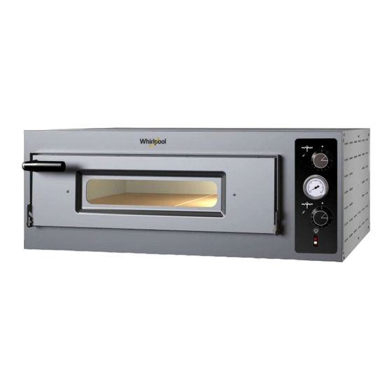
ENTRY BASIC ELECTRIC OVEN
FOUR ELECTRIQUE ENTRY BASIC
ENTRY BASIC ELECTRICOFEN
HORNO ELECTRICO ENTRY BASIC
ENTRY BASIC ЭЛЕКТРИЧЕСКАЯ ПЕЧЬ
IT
Manuale di istruzioni, uso e manutenzione
(Istruzioni originali)
EN
Instruction, use and maintenance manual
(Translation of the original instructions)
FR
Manuel d'instructions, d'utilisation et d'entretien
(Traduction de la notice originale)
DE
Bedienungs-, Gebrauchs- und Wartungsanleitung
(Übersetzung der Originalanleitung)
ES
Manual de instrucciones, uso y manutención
(Traducción de las instrucciones originales)
RU
Руководство по эксплуатации и техническому обслуживанию
(Перевод оригинальной инструкции)
Chapitres
Table des Matières

Manuels Connexes pour Whirlpool ENTRY BASIC


Sommaire des Matières pour Whirlpool ENTRY BASIC
- Page 1 FORNO ELETTRICO ENTRY BASIC ENTRY BASIC ELECTRIC OVEN FOUR ELECTRIQUE ENTRY BASIC ENTRY BASIC ELECTRICOFEN HORNO ELECTRICO ENTRY BASIC ENTRY BASIC ЭЛЕКТРИЧЕСКАЯ ПЕЧЬ Manuale di istruzioni, uso e manutenzione (Istruzioni originali) Instruction, use and maintenance manual (Translation of the original instructions)
-
Page 28: Déclaration De Conformité Χ
FR - Traduction de la notice originale DÉCLARATION DE CONFORMITÉ Χ Le constructeur dont le siège social se trouve déclare que les fours modèle : POM4/PZ, POM6/PZ sont conformes aux directives communautaires suivantes : 2006/42 CE - Directive Machine 2014/30 UE - Directive Compatibilité Électromagnétique UNI EN 453:2010 - Machines pour l’industrie alimentaire - Critères de sécurité... - Page 29 SOMMAIRE 1 AVANT-PROPOS ........................30 2 CONSIGNES DE SÉCURITÉ ..................... 30 Recommandations pour l’installateur ..................30 Recommandations pour l’utilisateur ..................30 Recommandations pour le personnel d'entretien ..............30 3 SPÉCIFICATIONS GÉNÉRALES ....................31 Caractéristiques ........................... 31 Données techniques ........................31 Schémas de câblage ........................
-
Page 30: Avant-Propos
1 AVANT-PROPOS Cher client, nous souhaitons tout d’abord vous remercier de la préférence que vous avez bien voulu nous accorder en achetant notre produit et souhaitons vous féliciter pour votre choix. Pour vous permettre de tirer le meilleur parti de votre nouveau four, veuillez suivre attentivement les instructions de ce manuel. -
Page 31: Spécifications Générales
3 SPÉCIFICATIONS GÉNÉRALES Caractéristiques Ci-après les spécifications générales qui caractérisent le four : Panneau de commandes frontal ; Plan de cuisson ; Passe-câbles alimentation ; Prise de courant équipotentielle ; Plaque signalétique. Données techniques Modèle Caractéristiques techniques POM4/PZ POM6/PZ LxPxH (cm) 99x92x38 99x127x38 Dimensions externes... -
Page 32: Schémas De Câblage
Schémas de câblage POM4/PZ – POM6/PZ 400V 3Ph+N+T... -
Page 33: Installation
4 INSTALLATION Déchargement et manutention du four Le déchargement et la manutention du four doivent être effectués au moyen d'un chariot élévateur par du personnel qualifié. Positionnement du four L’installation du four doit être faite par du personnel qualifié selon réglementations locales, nationales... -
Page 34: Raccordements Aux Circuits (Raccordement Électrique)
Raccordements aux circuits (raccordement électrique) Le four est fourni sans cordon d'alimentation. Le raccordement au réseau électrique doit être effectué en interposant un interrupteur magnétothermique différentiel avec des caractéristiques appropriées, dans lequel la distance d’ouverture minimale entre les contacts soit d’au moins 3 mm. Pour connecter le four au réseau électrique, il est indispensable de procéder comme indiqué... -
Page 35: Commandes
5 COMMANDES Description du panneau de commandes Étiquette de commande; 2. Interrupteur d'illumination de la chambre; 3. Thermomètre mécanique; 4. Thermostat Régulation Ciel; 5. Voyant lumineux température ciel; 6. Thermostat Régulation Plateau; 7. Voyant lumineux température plateau; Entaille Température (°C) 6 MODE D’EMPLOI Vérification fonctionnelle Avant d'allumer le four, vérifier :... -
Page 36: Mise En Fonctionnement
Mise en fonctionnement Tournez les boutons des thermostats et jusqu'à la température souhaitée. Ci faisant les résistances du ciel et du plateau sont activées ainsi que leur voyants lumineux. Indications générales de cuisson La pizza et les produits similaires, ont des durées et des températures de cuisson qui dépendent de la forme et de l'épaisseur de la pâte, ainsi que de la quantité... -
Page 37: Entretien Extraordinaire Sous La Responsabilité Des Techniciens Spécialisés
Entretien extraordinaire sous la responsabilité des techniciens spécialisés Pour toute opération non du ressort de l’utilisateur, demander l’assistance d’un technicien spécialisé. Contacter votre revendeur et/ou le service clientèle local. Avant d’effectuer toute opération d’entretien, débrancher l’alimentation électrique et suivre les « Précautions de sécurité... -
Page 38: Remplacement De La Vitre De La Porte
Remplacement de la vitre de la porte Enlever la façade des commandes sans débrancher les câbles. Dévisser l'écrou qui bloque le pivot à ressort et tourner le tournevis en sens antihoraire pour décharger le ressort. Enlever les vis du côté gauche de la porte et l'enlever du Démonter la contre-porte et remplacer la vitre cadre porte. -
Page 39: Indications Pour Commander Des Pièces Détachées
Indications pour commander des pièces détachées Pour commander des pièces détachées, les informations suivantes doivent être communiquées. Celles-ci figurent sur la plaquette argentée située sur le côté droit du four : • Modèle de four ; • Matricule du four (Numéro de Série) ; •... - Page 80 EXPLODED VIEW and SPARE PARTS LIST...