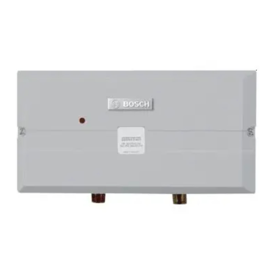
Bosch Tronic 3000 C Pro Instructions D'installation Et D'utilisation

Bosch Tronic 3000 C Pro Instructions D'installation Et D'utilisation

Masquer les pouces Voir aussi pour Tronic 3000 C Pro:
Table des Matières

Publicité

Les langues disponibles

Les langues disponibles

Liens rapides

Electric water heaters
Tronic 3000 C Pro
Model US12
en
Installation and Operating instructions
es
Instrucciones de instalación y funcionamiento
fr
Instructions d'installation et d'utilisation
IMPORTANT: This booklet should be given to the customer after installation and demonstration.
For Service & Installation contact:
BOSCH Thermotechnology Corp.
50 Wentworth Avenue, Londonderry
NH 03053 - 800-798-8161
www.bosch-climate.us
2
18
35

Publicité

Table des Matières
loading

Sommaire des Matières pour Bosch Tronic 3000 C Pro

  • Page 1 Electric water heaters Tronic 3000 C Pro Model US12 Installation and Operating instructions Instrucciones de instalación y funcionamiento Instructions d'installation et d'utilisation IMPORTANT: This booklet should be given to the customer after installation and demonstration. For Service & Installation contact: BOSCH Thermotechnology Corp.
  • Page 2: Table Des Matières

    2 | Table of contents Table of contents Explanation of Symbols and Important Safety Instructions ......3 Explanation of symbols .
  • Page 3: Explanation Of Symbols And Important Safety Instructions

    Important information B The Tronic 3000C Pro is designed to heat potable cold Important information that presents no risk water for domestic purposes. Contact Bosch to people or property is indicated with this Thermotechnology before specifying or installing the symbol. It is separated by horizontal lines appliance in any other application.
  • Page 4: Information About The Heater

    Horizontal installation Water connections Model name and number identification Model Name Model Number Tronic 3000 C Pro US 12 M W I H B Table 3 Package contents • Electric water heater • 4 No. 8 wood screws 6 720 647 088 (2011/09)
  • Page 5: General Description

    Information about the heater | 5 General description Outlet Inlet 6720646914-01.1V Fig. 1 Mouting hole Heat exchanger tube Control P.C.B Heating elements Terminal block Cable rear entry Ground stud Cable clamp Cable side entry Neon light Hi temp thermal cut-out (manual re-set) Cover fixing screw Flow switch 6 720 647 088 (2011/09)
  • Page 6: Function

    Do not supply with pre-heated water. • The cut-out will trip only in exceptional circumstances (Fig. 2). Call your service person or Bosch Thermotechnology Corp. if this happens frequently. • The flow switch senses water is passing through the unit.
  • Page 7: Regulations

    Regulations | 7 Regulations Any local by-laws and regulations pertaining to installation and use of electric water heater appliances must be observed. Please refer to the laws that should be attended in your country. • The electrical installation must conform to current National Electrical Codes.
  • Page 8: Installation

    B Bosch Thermotechnology Corp. is not modules. Bursts of air work better than continuous responsible for improperly installed flow.
  • Page 9: Water Connections

    If water quality exceeds one or more of the values specified below, Bosch recommends consulting a local water treatment professional for water softening/conditioning options. 6 720 647 088 (2011/09)
  • Page 10: Electrical Connections

    10 | Installation B Make sure that the ground wire is wrapped around its Electrical connections terminal stud and into the saddle washer. The nut should be tightened securely. Rated Rated Recommend B Attach the front cover and tighten the retaining Voltage Current Wire Size...
  • Page 11: Securing The Unit To The Wall

    Installation | 11 Securing the unit to the wall 4.5.1 Deciding the position B If the unit is to supply a sink, you can It it either above or below the sink. B If being used in a public place, position the unit out of reach to discourage vandalism.
  • Page 12: Mounting On The Wall

    12 | Installation 4.5.3 Mounting on the wall B Undo the retaining screws on the cover and take the cover of the unit. Hold the backplate in position against the wall while you mark the four mounting holes. B Drill the holes and secure the unit to the wall using the four no.
  • Page 13: Starting Up The Tronic 3000C Pro

    Starting up the Tronic 3000C Pro | 13 Starting up the Tronic 3000C Pro B The outlet shut off valve can be used to regulate WARNING: temperature or flow of water from the unit. B Do not use the unit if you think it may be frozen, as this could result in serious When using the hot water at a fixture, open damage to the unit.
  • Page 14: Appendix Flow Vs. Temperature Setting

    14 | Starting up the Tronic 3000C Pro Appendix Flow vs. Temperature Setting Guide The following graph Indicates the water temperatures the Thermostatic Tronic 3000C Pro can achieve at different flow rates. The graph shows the maximum and minimum temperatures achievable for the 12 kW unit with an inlet water temperature of 50°.
  • Page 15: Troubleshooting

    Troubleshooting If the problem persists: The person who initially installed the unit is probably the best one to contact for help. You can also call Bosch Thermotechnology Corporation at 800-798-8161 or visit www.bosch-climate.us. Please have this guide with you when you call.
  • Page 16: For The User

    16 | Troubleshooting For the User Symptom Cause What do do Little or no water flows. The water supply is turned off. Turn on the main supply fully at the stop valve. Cold water only -neon light The flow is not high enough to Open the inlet service valve fully.
  • Page 17: Interior Components And Parts List

    Front Cover (not shown) Table 8 For further information ask your local dealer. FOR SERVICE AND INSTALLATION QUESTIONS CALL: Tel: 800-798-8161 Fax: 603-965-7581 Bosch Thermotechnology Corporation Bosch Thermotechnology Corp. 50 Wentworth Avenue Londonderry, NH 03053 Phone 800-798-8161 Fax 603-965-7581 www.bosch-climate.us techsupport@bosch-climate.us...
  • Page 18 18 | Tabla de contenidos Tabla de contenidos Explicación de los símbolos e instrucciones importantes de seguridad ....19 Explicación de los símbolos ... 19 Instrucciones Importantes de Seguridad .
  • Page 19: Explicación De Los Símbolos E Instrucciones Importantes De Seguridad

    Información importante B El Tronic 3000C Pro está diseñado para calentar agua Información importante que no presenta fría potable para uso doméstico. Contacte a Bosch ningún riesgo para las personas o los bienes Thermotechnology antes de especificar o instalar el se indica con este símbolo.
  • Page 20: Información Sobre El Calentador

    Conexiones de agua Identificación de nombre y número de modelo Nombre de modelo Número de modelo Tronic 3000 C Pro US 12 M W I H B Table 3 Contenido del paquete • Calentador de agua eléctrico • 4 tornillos para madera Nº 8...
  • Page 21: Descripción General

    Información sobre el calentador Descripción general Entrada Salida 6720646914-01.1V Fig. 1 Orificio de montaje Tubo del intercambiador de calor Control P.C.B Elementos de calentamiento Bloque terminal Cable de entrada trasera Clavija de tierra Abrazadera de cable Entrada lateral del cable Luz de neón Corta circuito térmico de alta temperatura (restableci- miento manual)
  • Page 22: Función

    • El corta circuitos se disparará sólo en circunstancias calentada. excepcionales (Fig. 2). Llame a su personal de servicio o Bosch Thermotechnology Corp. si esto • El interruptor de caudal siente cuando el agua está sucede con frecuencia. pasando a través de la unidad. Si se detecta más que el nivel preestablecido, se enciende la unidad de calentamiento de los elementos.
  • Page 23: Reglamentos

    Reglamentos Reglamentos Se debe cumplir cualquier ley y reglamentos locales relativos a la instalación y el uso de aparatos eléctricos calentadores de agua. Por favor, consulte las leyes que deben ser atendidas en su país. • La instalación eléctrica debe ajustarse a las actuales National Electrical Codes.
  • Page 24: Instalación

    B Desconecte el suministro eléctrico. estas instrucciones. B Desconecte las tuberías de agua fría y caliente de las B Bosch Thermotechnology Corp. no se conexiones en la parte inferior del calentador. Deje hace responsable de los aparatos que no que el agua drene hacia afuera (tenga lista una cubeta estén bien instalados.
  • Page 25: Conexiones De Agua

    Si la calidad del agua excede uno o más de los valores fuente principal de agua fría y no con agua que se especifican a continuación, Bosch recomienda precalentada. El aparato debe ser instalado con consultar a un profesional local en tratamiento de válvulas de servicio tanto en la entrada como en la...
  • Page 26: Conexiones Eléctricas

    Instalación B Asegúrese de que el cable de tierra está enrollado en Conexiones eléctricas el vástago terminal y en la arandela de montaje. La tuerca debe estar apretada firmemente. Valoradas B Coloque la cubierta delantera y apriete los tornillos Valoradas Tamaño Recomendar de fijación.
  • Page 27: Asegurar La Unidad A La Pared

    Instalación Asegurar la unidad a la pared 4.5.1 Decidir la posición B Si la unidad va a suministrar un fregadero, lo puede hacer ya sea por encima o por debajo del fregadero. B Si se utiliza en un lugar público, coloque la unidad fuera del alcance para evitar el vandalismo.
  • Page 28: Montaje En La Pared

    Instalación 4.5.3 Montaje en la pared B Afloje los tornillos de sujeción de la cubierta y quite la cubierta de la unidad. Sujete la placa posterior en posición contra la pared mientras que marca los cuatro orificios de montaje. B Taladre los orificios y fije la unidad a la pared utilizando los cuatro tornillos para madera no.
  • Page 29: Puesta En Marcha Del Tronic 3000C Pro

    Puesta en marcha del Tronic 3000C Pro Puesta en marcha del Tronic 3000C Pro B Adjust the outlet service valve till the water comes out ADVERTENCIA: of the tap at the recommended flow rate for the B No utilice la unidad si cree que puede required temperature.
  • Page 30: Apéndice Flujo Vs Temperatura Guía De Configuración

    Puesta en marcha del Tronic 3000C Pro B Vuelva a colocar la placa de identificación. Fig. 7 Eje de ajuste de temperatura Apéndice Flujo vs Temperatura Guía de Configuración El siguiente gráfico indica la temperatura del agua que el Thermostatic Tronic 3000C Pro puede lograr con diferentes rangos de flujo.
  • Page 31 Puesta en marcha del Tronic 3000C Pro Es recomendable configurar el eje de ajuste de temperatura a la posición máxima. (Véa- se el siguiente gráfico). Si es necesario, ajuste la válvula de servicio de salida hasta que el agua salga de la llave a la temperatura deseada (aumente el flujo de agua fría, disminuyen el flujo de agua ca- liente).
  • Page 32: Solución De Problemas

    Si el problema persiste: La persona que instaló inicialmente la unidad es probablemente el mejor para ponerse en contacto para pedir ayuda. También puede llamar al Bosch Thermotechnology Corporation al 800-798-8161 o visite www.bosch-climate.us. Por favor tenga esta guía con usted cuando llame.
  • Page 33: Para El Usuario

    Solución de problemas Para el Usuario Síntoma Causa ¿Qué hacer? Poco o nada de flujo de El suministro de agua está Abra totalmente el suministro principal la válvu- agua. cerrado. la de cierre. Agua fría solamente -luz de El flujo no es suficiente para acti- Abra totalmente la válvula de servicio de neón apagada.
  • Page 34: Componentes Interiores Y Lista De Piezas

    (no se muestra) Table 8 Para más información consulte con su distribuidor local. PARA PREGUNTAS DE SERVICIO E INSTALACIÓN: LLAME AL Tel: 800-798-8161 Fax: 603-965-7581 Bosch Thermotechnology Corporation Bosch Thermotechnology Corp. 50 Wentworth Avenue Londonderry, NH 03053 Phone 800-798-8161 Fax 603-965-7581 www.bosch-climate.us...
  • Page 35 Sommaire Sommaire Explication des symboles et instructions de sécurité importantes ..... 36 Explication des symboles ... . 36 Importantes instructions de sécurité...
  • Page 36: Explication Des Symboles Et Instructions De Sécurité Importantes

    Informations importantes B Le Tronic 3000C Pro est conçu pour de l'eau froide Les informations importantes qui ne présen- potable à usage domestique. Contacter Bosch Ther- tent pas de risque pour les personnes ni motechnology avant designer ou utiliser l'appareil pour la propriété...
  • Page 37: Informations Relatives Au Chauffe-Eau

    Raccordements eau Nom du modèle et numéro d'identifi- cation Nom du modèle Numéro d'identification Tronic 3000 C Pro US 12 M W I H B Tab. 3 Contenu du carton • Chauffe-eau électrique • 4 vis à bois No. 8...
  • Page 38: Description Générale

    Informations relatives au chauffe-eau Description générale Sortie Entrée 6720646914-01.1V Fig. 1 Trou de fixation Tube d'échangeur thermique Carte circuit imprimé pour contrôle Résistances électriques Bornier Entrée arrière du câble Borne de masse Serre-câble Entrée côté du câble Lampe néon Protecteur thermique haute température (à réenclenche- ment manuel) Sélecteur d'alimentation Fluxostat...
  • Page 39: Fonction

    (Fig. 2). Si cela se produit fréquem- ment, veuillez contacter votre technicien de service • Le fluxostat capte que l'eau passe par l'unité. Si le ou Bosch Thermotechnology Corp. niveau d'eau détecté est supérieur au niveau préréglé, les résistances électriques se déconnectent. Ceci est indiqué...
  • Page 40: Règlementations

    Règlementations Règlementations Toutes lois règlementations relatives à l'installation et à l'utilisation des chauffe-eau électriques doivent être appliquées. Veuillez vous renseigner sur les lois en vigueur dans votre pays. • L'installation électrique doit être conforme aux Codes électriques nationaux en vigueur. •...
  • Page 41: Installation

    B Une fois la vidange terminée, envoyer de l'air compri- ent aux présentes instructions.. mé basse pression à l'intérieur du chauffe-eau afin de B Bosch Thermotechnology Corp. n'est en faire sortir le plus d'eau possible des modules. Il est aucun cas responsable de la mauvaise conseillé...
  • Page 42: Raccordements D'eau

    Si la qualité de l'eau excède une ou plusieurs des chauffée. Elle doit être installée avec des vannes d'isolement d'entrée et de sortie. Ces robinets peu- valeurs référencées ci-après, Bosch recommande de consulter un professionnel du traitement des eaux vent être utilisés pour couper l'alimentation en eau vers l'unité...
  • Page 43: Branchements Électriques

    Installation B Fixer le capot frontal et visser les vis de fixation. Branchements électriques Taille de Tension Courant câble nominal nominal recommand ée (AWG) Model US12 Tab. 5 B Dénuder l'isolation des câbles électriques sur environ 3/8 pouces. L'isolation des câbles de masse doit être dénudée sur environ 3/4".
  • Page 44: Fixation De L'unité Au Mur

    Installation Fixation de l'unité au mur 4.5.1 Choix de l'emplacement B Si l'unité est prévue pour alimenter un seul point de puisage, il est possible de l'installer au dessus ou en B En cas d'installation dans un espace public, placer dessous du point de puisage.
  • Page 45: Fixation Sur Le Mur

    Installation B Passer le câble par le passe câble avant de monter l'unité sur le mur. En cas d'utilisation d'une garniture de câble agréée, retirer la gaine en caoutchouc. 4.5.3 Fixation sur le mur B Dévisser les vis de fixation du capot et retirer le capot. Maintenir la plaque arrière en position le long du mur et marquer les quatre trous de fixation.
  • Page 46: Mise En Marche Du Tronic 3000C Pro

    Mise en marche du Tronic 3000C Pro Mise en marche du Tronic 3000C Pro B Vérifier que l'unité fonctionne correctement lorsque AVERTISSEMENT : le robinet du point de puisage est fermé puis ouvert B Ne pas utiliser l'unité s'il y a eu un risque de nouveau ;...
  • Page 47: Annexe Guide De Réglage Du Débit Par Rapport À La Température

    Mise en marche du Tronic 3000C Pro Annexe Guide de réglage du débit par rapport à la température Le graphique suivant indique les températures de l'eau que peut atteindre le ThermostatiqueTronic 3000C Pro à différents débits. Ce graphique indique les températures minimales et maximales atteignables pour l'unité de 12 kW avec une température de l'eau à...
  • Page 48: Diagnostic De Pannes

    Si le problème persiste: Contactez la personne qui a initialement installé le chauffe-eau pour toute aide. Vous pouvez également contacter Bosch Thermotechnology Corporationau 800-798-8161 ou sur le site www.bosch-climate.us. Veuillez avoir sous les yeux le présent guide au moment de l'appel.
  • Page 49: Pour L'utilisateur

    Diagnostic de pannes Pour l'utilisateur Symptôme Cause Solution Débit faible ou pas de déb- L'alimentation en eau est coupée. Ouvrir l'alimentation générale complètement au robinet d'arrêt. Eau froide seulement - Le flux n'est pas assez fort pour Ouvrir à fond la vanne d'isolement d'entrée. lampe néon éteinte.
  • Page 50: Liste Des Composants Et Des Pièces Internes

    Capot avant (pas indiqué) Tab. 8 Pour plus d'information, consultez votre revendeur local. POUR TOUTE QUESTION TECHNIQUE ET D'INSTALLATION, VEUILLEZ APPELER : Tel: 800-798-8161 Fax: 603-965-7581 Bosch Thermotechnology Corporation Bosch Thermotechnology Corp. 50 Wentworth Avenue Londonderry, NH 03053 Phone 800-798-8161 Fax 603-965-7581 www.bosch-climate.us...
  • Page 51 Liste des composants et des pièces internes 6 720 647 088 (2011/09)
  • Page 52 For Service & Installation contact: BOSCH Thermotechnology Corp. 50 Wentworth Avenue, Londonderry NH 03053 Phone: 800-798-8161 Fax: 603-965-7581 www.bosch-climate.us...

Ce manuel est également adapté pour:

Us12

Table des Matières