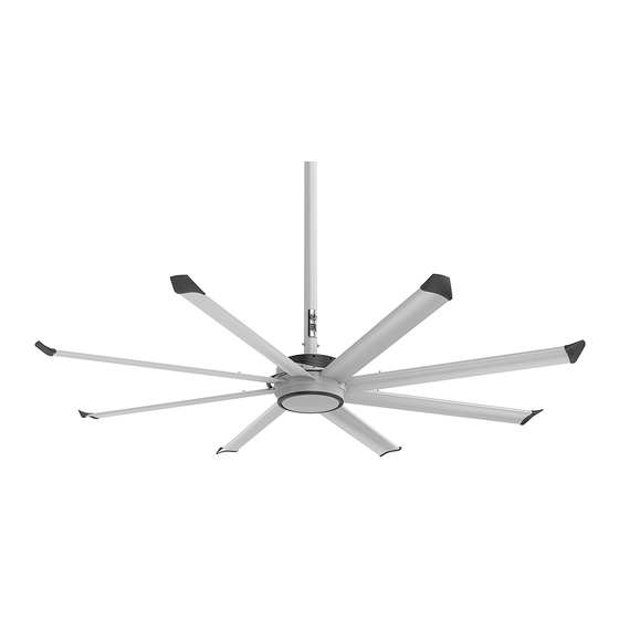
BIG ASS FANS Essence Manuel D'installation
Masquer les pouces
Voir aussi pour Essence:
- Installation (24 pages) ,
- Guide d'installation rapide (33 pages) ,
- Manuel d'installation (13 pages)
Publicité
Table des Matières
Quick Installation Guide
Manuel d'installation rapide Guía de instalación rápida
Essence
READ AND SAVE THESE INSTRUCTIONS
LIRE ET CONSERVER CES INSTRUCTIONS
LEA Y CONSERVE ESTAS INSTRUCCIONES
Input Power and Required Breaker
Alimentation et calibre du disjoncteur | Potencia de entrada y disyuntor requerido
110–125 V , 50/60 Hz, 1 Ф, 10 A
200–240 V , 50/60 Hz, 1 Ф, 10 A
1. UPPER MOUNT & EXTENSION TUBE
Refer to the instructions included for your mounting structure.
Reportez-vous aux instructions fournies pour votre structure de montage.
Consulte las instrucciones incluidas para su estructura de montaje.
2. FAN & SAFETY CABLE
If your fan order included guy wires, install them according to the instructions included with the guy wire kit.
Si vous avez commandé les haubans, installez-les en suivant les instructions fournies avec le kit des haubans.
Si junto con su ventilador pidió los cables de sujeción, instálelos de acuerdo con las instrucciones incluidas con el kit de los cables de sujeción.
Do not remove main
fan unit from protective
packaging prior to hanging.
Ne retirez pas le corps du
ventilateur de son emballage tant
que vous ne l'avez pas accroché.
No retire la unidad principal
del ventilador de su embalaje
protector antes de colgarla.
®
VENTILATEUR ET ÉLINGUE DE SÉCURITÉ
6–10 in.
(152–254 mm)
5/16 in. Clevis Pin
Operating Instructions and Maintenance:
Instructions d'utilisation et entretien :
Instrucciones de operación y mantenimiento:
bigassfans.com/support
Intensité maximale | Amperaje a plena carga
SYSTÈME DE FIXATION SUPÉRIEUR ET TIGE DE PROLONGATION
MONTURA SUPERIOR Y TUBO DE EXTENSIÓN
Cotter Pin
Full Load Amps
6.0 A
3.6 A
VENTILADOR Y CABLE DE SEGURIDAD
M8 x 75 mm Socket Head Cap Screw
M8 Flat Washer
M8 Nylock Nut
25 ft·lb (33.9 N·m)
Publicité
Table des Matières

Manuels Connexes pour BIG ASS FANS Essence


Sommaire des Matières pour BIG ASS FANS Essence
- Page 1 Quick Installation Guide Manuel d’installation rapide Guía de instalación rápida Essence ® Operating Instructions and Maintenance: READ AND SAVE THESE INSTRUCTIONS Instructions d’utilisation et entretien : LIRE ET CONSERVER CES INSTRUCTIONS Instrucciones de operación y mantenimiento: LEA Y CONSERVE ESTAS INSTRUCCIONES bigassfans.com/support...
-
Page 2: Tighten Hardware
3. TIGHTEN HARDWARE SERRAGE DE LA VISSERIE AJUSTAR LOS ACCESORIOS Bar Joist Mounting Montage sur poutrelles Instalación en vigas de celosía 25 ft·lb (33.9 N·m) 25 ft·lb (33.9 N·m) 40 ft·lb (54.2 N·m) Allow extension tube to hang freely and balance itself, and then tighten. Laissez la tige de prolongation pendre librement et se stabiliser, puis serrez. - Page 3 Contactez Big Ass Fans pour plus de détails. Si va a instalar la luz LED en los ventiladores Essence (disponible solo en regiones seleccionadas), instálela de acuerdo con las instrucciones incluidas con la luz. Comunícate con Big Ass Fans para obtener más información.
-
Page 4: Lower Cover
5. LOWER COVER CACHE INFÉRIEUR CUBIERTA INFERIOR Do not install lower cover if installing the LED light. N’installez pas le cache inférieur si vouz installez l’éclairage à DEL. No instale la cubierta inferior si se instala la luz LED. Remove protective cover sheet from bottom of main fan unit before installing lower cover. - Page 5 Skip this step if installing Essence with UV-C Technology. Refer to the instructions provided with the UV-C light. Ignorez cette étape si vous installez un modèle Essence muni de la technologie UV-C. Consultez les instructions fournies avec la lampe UV-C.
- Page 6 If installing Essence with UV-C Technology, do not connect fire relay wiring. Refer to the instructions provided with the UV-C light. Si vous installez un modèle Essence muni de la technologie UV-C, ne branchez pas le câblage de relais d’incendie. Consultez les instructions fournies avec la lampe UV-C.
-
Page 7: Wall Controller
9. WALL CONTROLLER DISPOSITIF DE COMMANDE MURAL CONTROLADOR DE PARED Make sure the CAT5 controller cable is routed from the junction box to the controller installation location. Refer to the instructions that came in the controller box for controller installation details. Vérifi ez que le câble CAT5 du dispositif de commande a été... - Page 8 NOTES NOTES NOTAS Suitable for use in wet locations when installed in a GFCI protected branch circuit. Ce ventilateur peut être utilisé dans des pièces humides, à condition qu’il soit installé sur un circuit de dérivation protégé par un disjoncteur différentiel. Apto para uso en lugares húmedos si se instala en un circuito secundario protegido con un interruptor diferencial.