Table des Matières

Publicité

Les langues disponibles

Les langues disponibles

Liens rapides

INSTALLATION
GUIDE
Isis
®
For help, call 1-877-BIG-FANS
Guide d'installation
or visit www.bigassfans.com

Publicité

Chapitres

Table des Matières
loading

Sommaire des Matières pour BIG ASS FANS Isis

  • Page 1 INSTALLATION GUIDE Isis ® For help, call 1-877-BIG-FANS Guide d’installation or visit www.bigassfans.com...
  • Page 2: Installation Checklist

    Isis ® Installation Checklist Did a structural engineer approve the mounting structure? See page 7 for Big Ass Fans-approved mounting structures. Will the fan be installed so that the airfoils are at least 10 ft (3.05 m) above the floor? Will the fan be installed so that the airfoils have at least 2 ft (0.61 m) of clearance from...
  • Page 3 Isis ® Installation Guide Isis ® Installation Guide: Rev. I 04/16/2020 Conforms to UL 507: Electric Fans Conforms to UL 507: Electric Fans Certified to CSA C22.2 No. 113: Fans & Ventilators Certified to CSA C22.2 No. 113: Fans & Ventilators All trademarks used herein are the properties of their respective owners.
  • Page 4 CAUTION: Exercise caution and common sense when powering the fan. Do not connect the fan to a damaged or hazardous power source. Do not attempt to resolve electrical malfunctions or failures on your own. Contact Big Ass Fans if you have any questions regarding the electrical installation of this fan.
  • Page 7: Table Des Matières

    Isis ® Contents General Information Important Safety Information Reference Guide Reference Guide (Mounting) Introduction About this Fan Pre-Installation What’s in the Box Parts Included Alternative Mounting Methods Tools Needed Fan Diagram Preparing the Work Site Mounting Structure: 1. Select Proper Angle Irons 2.
  • Page 8 Isis ® Contents Fan Operation Fan Operation Changing the Fan Direction Alternative Wiring Limited Access Application Limited Access Fan Controller and Controller Remote Operation Methods 3-Way Single Fan Application Preventive Maintenance Annual Preventive Maintenance General Preventive Maintenance Annual Maintenance Annual Maintenance Checklist...
  • Page 9 Isis ® Introduction About this fan 110–125 VAC Isis (indoor) Minimum required Full load Fan diameter Input power Airfoil length supply circuit size amps 8 ft (2.44 m) 110–125 VAC, 60 Hz 10 A 40” (101 cm) 10 ft (3.04 m) 110–125 VAC, 60 Hz...
  • Page 10: What's In The Box

    3. Safety clips and carabiners are only used when the top of the mounting structure is inaccessible. 4. Winglets are standard on Isis fans; however, airfoil tips are available as an option. Winglets or airfoil tips are installed on the airfoils during airfoil installation.
  • Page 11: Parts Included

    1. The safety cable is attached to the extension tube with a 3/8” bolt and nut. 2. Optional. L-Brackets or the Wood Frame Mounting kit are included only if ordered. Note: L-Bracket hardware is customer-supplied. Big Ass Fans recommends using 1/2”- 13 or M12 Grade 8 hardware.
  • Page 12 I-Beam Adapter The I-beam adapter can be purchased for hanging the Isis from I-beams. Big Ass Fans offers both a small and large adapter depending on the width of the I-beam. The I-Beam Adapter can only be used on I-beams that are 5” (12.7 cm) to 9-7/8” (25 cm) (small adapter) or 9-7/8”...
  • Page 13: Tools Needed

    Isis ® Pre-Installation (cont.) Tools needed Big Ass Fans recommends gathering the following tools prior to beginning installation. Mechanical installation Electrical installation Standard and metric wrench sets Phillips and flat head screwdrivers Standard and metric socket and ratchet sets #10 to #14 AWG strippers Medium size channel locks Torque wrench capable of 29 ft·lb (39.3 N·m)
  • Page 14: Fan Diagram

    C. Main fan unit. Includes motor, hub, lower mount, and power wire. D. Airfoil. Provides air movement. The unique, patented design provides efficient and effective air movement. E. Winglet. Improves the efficiency of the fan. Winglets are standard on Isis fans; however, airfoil tips are available as an option.
  • Page 15 • If installing the fan on a typical lighting circuit with one basic light switch in which the critical red conductor or “traveler” is absent, you will need to purchase the Limited Access Controller. Please discuss this option with your Big Ass Fans representative.
  • Page 16 Notes...
  • Page 17: Select Proper Angle Irons

    A structural engineer should verify that the mounting structure is adequate prior to fan installation. Verifying the stability of the mounting structure is the sole responsibility of the customer and/or end user, and Big Ass Fans hereby expressly disclaims any liability arising therefrom, or arising from the use of any materials or hardware other than those supplied by Big Ass Fans or otherwise specified in these installation instructions.
  • Page 18: Pre-Drill Angle Irons

    Isis ® Mounting Structure: Bar Joists (cont.) 2. Pre-drill angle irons Drill two Ø 7/16” (1.1 cm) holes exactly 5-1/2” (14 cm) apart in the centers of two angle irons. Measure the distance between the mounting points of the roof structure that the angle irons will span. Measure the same distance on the angle irons, and drill Ø...
  • Page 19: 4A. Fasten Single Angle Irons To Roof Structure Mounting Points

    Fasten the angle irons to the roof structure mounting points at each end with customer-supplied Grade 8 hardware as shown. Do not tighten the hardware until the fan has been mounted to the angle irons. Note: Big Ass Fans recommends orienting the angle irons so that the horizontal legs are facing each other.
  • Page 20: 4B. Fasten Double Angle Irons To Roof Structure Mounting Points

    Isis ® Mounting Structure: Bar Joists (cont.) 4b. Fasten double angle irons to roof structure mounting points CAUTION: The angle irons must be fastened to the roof structure at each end. Fasten the angle irons to the roof structure mounting points at each end with customer-supplied Grade 8 hardware as shown. Do not tighten the hardware until the fan has been mounted to the angle irons.
  • Page 21: Attach Upper Mount (To Angle Irons)

    Isis ® Mounting Structure: Bar Joists (cont.) 5. Attach upper mount (to angle irons) Secure the upper mount directly to the angle irons using the Mounting Hardware as shown. Consult the diagrams below for distances between the angle irons. Tighten the Mounting Hardware to 25 ft·lb (33.9 N·m) using a torque wrench with a 17 mm socket.
  • Page 22: Identify Mounting Location

    CAUTION: Do not install the fan from a single beam or a conduit box. Locate the area on the beams from which the fan will hang. Big Ass Fans recommends mounting the fan so that the airfoils are at least 10 ft (3 m) from the floor.
  • Page 23: 2B. Fasten Brackets (To Floor Joists)

    Isis ® Mounting Structure: Wood Frame (cont.) 2b. Fasten brackets (to floor joists) Note: This method should be used when the tops of the joists are inaccessible. Fasten the brackets to the mounting points on the floor joists using the Wood Frame Mounting Hardware as shown. Torque to 25 ft·lb (33.9 N·m).
  • Page 24: Attach Upper Mount (To Wood Framing Channels)

    Isis ® Mounting Structure: Wood Frame (cont.) 3. Attach upper mount (to wood framing channels) When cutting the wood framing channels, be sure the holes on each end will line up with the holes on the mounting brackets! Loosely attach the extension tube to the upper mount to determine where on the channels the mount should be attached. Fasten the mount to the wood framing channels using the Mounting Hardware as shown.
  • Page 25: Fasten Wood Framing Channels (To Brackets)

    Isis ® Mounting Structure: Wood Frame (cont.) 4. Fasten wood framing channels (to brackets) CAUTION: The center-to-center distance between the two beams or joists between which the fan will hang cannot be greater than 24” (61 cm). Fasten the wood framing channels to the brackets using the Wood Frame Mounting Hardware as shown. Torque to 25 ft·lb (33.9 N·m).
  • Page 26: Determine Bracket Orientation

    A structural engineer should verify that the structure is adequate prior to fan installation. Verifying the stability of the mounting structure is the sole responsibility of the customer and/or end user, and Big Ass Fans hereby expressly disclaims any liability arising therefrom, or arising from the use of any materials or hardware other than those supplied by Big Ass Fans or otherwise specified in these installation instructions.
  • Page 27: 3A. Attach L-Brackets (To Mounting Structure)

    Isis ® Mounting Structure: Solid Beam (cont.) 3a. Attach L-brackets (to mounting structure) Fasten the L-brackets to the mounting structure using the customer-supplied 1/2-13 or M12 L-Bracket Hardware as shown below. Note: L-bracket orientation may differ from the illustration. L-Bracket Hardware (Customer-Supplied): a.
  • Page 28: Attach Extension Tube (To Upper Mount)

    Isis ® Hanging the Fan 1. Attach extension tube (to upper mount) Pull the safety cable that is attached to the extension tube through the upper mount, and then fasten the extension tube to the upper mount (already attached to the mounting structure) using the Extension Tube Upper Hardware as shown.
  • Page 29: 2C. Secure Safety Cable (To Solid Beam)

    Isis ® Hanging the Fan (cont.) 2c. Secure safety cable (to solid beam) WARNING: The safety cable is a crucial part of the fan and must be installed correctly. If you have any questions, call Customer Service. Secure the safety cable to the mounting structure by wrapping it around the structure and securing the loose end with the Gripple as shown.
  • Page 30: Attach Guy Wire Clamps

    Isis ® Installing Guy Wires Guy wires may not be included in your fan order. They are intended to restrain the fan’s lateral movement and are only included in fan orders that have extension tubes 4 ft (1.2 m) or longer. Depending on the operational environment (wind, mounting structure, etc.), guy wires may be needed regardless of extension tube length.
  • Page 31: Attach Locking Carabiners To Guy Wire Clamps

    Isis ® Installing Guy Wires (cont.) 2. Attach locking carabiners to guy wire clamps Secure the four (4) locking carabiners to the guy wire clamps as shown. Securely tighten the carabiners. 3a. Attach beam clamp (bar joist mounting) The guy wire should be at a 45° angle from the extension tube (see the illustrations on the following page).
  • Page 32: Route Guy Wire Through Gripple

    Isis ® Installing Guy Wires (cont.) 4. Route guy wire through Gripple ® Route the guy wire through the Gripple and the carabiner on the guy wire clamp, and then back through the Gripple as shown below. Do not tighten the Gripple until the remaining guy wires have been installed.
  • Page 33: Attach Winglets Or Airfoil Tips (To Airfoils)

    Isis ® Installing Airfoils Big Ass Fans recommends completing electrical installation (page 27) before installing the airfoils. WARNING: Disconnect power to the fan before installing the airfoils. 1. Attach winglets or airfoil tips (to airfoils) Note: Winglets are standard on Isis fans;...
  • Page 34: Attach Airfoils (To Main Fan Unit)

    Isis ® Installing Airfoils (cont.) 3. Attach airfoils (to main fan unit) After the fan is completely assembled and securely hanging from the mounting structure, peel off the protective plastic from the bottom of the hub. WARNING: Disconnect power to fan before installing airfoils.
  • Page 35: Electrical Installation Safety

    WARNING: Exercise caution and common sense when powering the fan. Do not connect the fan to a damaged or hazardous power source. Do not attempt to resolve electrical malfunctions or failures on your own. Contact Big Ass Fans if you have any questions regarding the electrical installation of this fan.
  • Page 36: Wiring: Single Fan Application

    Isis ® Electrical Installation (cont.) Wiring: single fan application A wall controller is provided only with fans sold in the United States, Canada, and Saudi Arabia. Customers outside of these countries must supply a lighting dimmer rated for incandescent loads only.
  • Page 37: Wiring: Multi-Fan Application

    Isis ® Electrical Installation (cont.) Wiring: multi-fan application A wall controller is provided only with fans sold in the United States, Canada, and Saudi Arabia. Customers outside of these countries must supply a lighting dimmer rated for incandescent loads only.
  • Page 38: Mounting The Wall Controller

    Isis ® Electrical Installation (cont.) Mounting the wall controller A wall controller is provided only with fans sold in the United States, Canada, and Saudi Arabia. Customers outside of these countries must supply a lighting dimmer rated for incandescent loads only.
  • Page 39: Fan Operation

    Isis ® Fan Operation To start the fan, tap the upper portion of the pushpad once. The fan may take up to 30 seconds to begin rotating. To stop the fan, tap the lower portion of the pushpad once. To disable the fan, pull out the clear tab at the bottom of the controller.
  • Page 40: Changing The Fan Direction

    Isis ® Fan Operation (cont.) Changing the fan direction CAUTION: When adjusting the fan direction selector switch, be careful not to damage internal components! CAUTION: Do not insert foreign objects into the fan direction selector switch. To reverse the direction of the fan, remove power from the fan. Select the direction of the fan using the fan direction selector switch.
  • Page 41: Alternative Wiring Methods

    Illustrated on the right is a typical lighting circuit with one basic light switch. The fan operational critical red Existing Switch conductor or “traveler” conductor is absent. For Isis ® applications in which installing a 3-wire plus ground circuit Box on Wall...
  • Page 42: Wall Controller

    Alternative Wiring Methods (cont.) Limited access fan controller and controller remote operation As a convenience, the fan controller and the controller remote sets are factory paired by Big Ass Fans. See the previous page for wiring instructions. To start the fan, tap the upper portion of the pushpad once. The fan may take up to 30 seconds to start rotating. To increase fan speed, press and hold the upper portion of the pushpad.
  • Page 43 Isis ® Alternative Wiring Methods (cont.) 3-way single fan application CAUTION: The fan must operate on a dedicated circuit with a dedicated neutral. Failure to install the fan on a dedicated circuit can cause the fan to operate improperly. WWW.BIGASSFANS.COM ©2014 DELTA T LLC...
  • Page 44: Annual Preventive Maintenance

    Isis ® Preventive Maintenance WARNING: Before servicing or cleaning unit, switch power off at service panel and lock the service disconnecting means to prevent power from being switched on accidentally. When the service disconnecting means cannot be locked, securely fasten a prominent warning device (such as a tag) to the service panel.
  • Page 45: Annual Maintenance Checklist

    Isis ® Annual Maintenance Checklist Fan Model: Fan Model: Fan Model: Serial #: Serial #: Serial #: Location: Location: Location: Date Initials Date Initials Date Initials WWW.BIGASSFANS.COM ©2014 DELTA T LLC ALL RIGHTS RESERVED...
  • Page 47: General Troubleshooting

    Isis ® Troubleshooting WARNING: When servicing or replacement of a component in the fan requires the removal or disconnection of a safety device, the safety device is to be reinstalled or remounted as previously installed. CAUTION: Use this unit only in the manner intended by the manufacturer. If you have questions, contact the manufacturer.
  • Page 48: Replacing Fuses

    Isis ® Troubleshooting (cont.) Replacing fuses WARNING: Ensure power is disconnected before replacing fuses. To replace the fuses on the main fan unit, remove the screw securing the fuse cover. Replace the appropriate fuse, and reinstall the cover. Refer to the table below for fuse recommendations. Note: If your fan’s fuse cover is in a different location than shown below, contact Customer Service for assistance.
  • Page 49: Customer Service

    40150 Shah Alam, Selangor, Malaysia (+603) 5565 0888 Manufacturing and Warranty You are responsible for providing and paying for shipping when returning a product to Big Ass Fans for the purpose of recycling under the WEEE directive. Manufacturer Warranty and WEEE Returns...
  • Page 51 MANUEL D’INSTALLATION Isis ® Pour obtenir de l’aide, appelez le 1 877 BIG-FANS ou rendez-vous sur www.bigassfans.com...
  • Page 52: Points Clés À Vérifier Avant L'installation

    Si vous avez commandé plusieurs ventilateurs, avez-vous bien séparé les pièces de chaque ventilateur ? Quel est le type de circuit installé dans votre bâtiment : 3 fils ou 2 fils ? Le ventilateur Isis ® livré avec un dispositif de commande compatible avec les circuits 3 fils. Si votre bâtiment est équipé...
  • Page 53 Toutes les marques de commerce utilisées dans le présent document sont la propriété de leurs propriétaires respectifs. Aucune partie de ce document ne peut être reproduite ou traduite en une autre langue sans avoir obtenu préalablement le consentement écrit de Big Ass Fans. Les informations que contiennent ce document sont sujettes à des changements sans préavis. Pour les dernières informations disponibles, consultez le guide d’installation en ligne au www.bigassfans.com.
  • Page 54: Consignes De Sécurité Importantesà Lire Et Conserver En Lieu Sûr

    Isis ® CONSIGNES DE SÉCURITÉ IMPORTANTES À LIRE ET CONSERVER EN LIEU SÛR VEUILLEZ RESPECTER LES CONSIGNES SUIVANTES POUR LIMITER LES RISQUES D'INCENDIE, D'ÉLECTROCUTION ET DE DOMMAGES CORPORELS : ATTENTION : L'installation et le raccordement électrique du ventilateur doivent être réalisés par une ou plusieurs personnes qualifiées, dans le respect des codes et normes applicables.
  • Page 57 Isis ® Sommaire Présentation générale Consignes de sécurité importantes ..................ii Aide-mémoire ........................iii Aide-mémoire (ancrage) ......................iv Introduction Caractéristiques du ventilateur ....................1 Avant l’installation Contenu de la boîte ....................... 2 Composants fournis....................... 3 Autres techniques de montage ....................4 Outils nécessaires ......................... 5 Schéma du ventilateur ......................
  • Page 58 Isis ® Sommaire Utilisation du ventilateur Utilisation du ventilateur ...................... 31 Inversion du sens de rotation du ventilateur ................ 32 Autres techniques de Accès restreint ........................33 Fonctionnement du système de commande à accès restreint avec commande à distance ..34 raccordement Va-et-vient pour un seul ventilateur ..................
  • Page 59: Introduction

    Isis ® Introduction Caractéristiques du ventilateur 110–125 V CA Isis (intérieur) Caractéristiques Vitesse Intensité Longueur des Diamètre du ventilateur Alimentation minimales du circuit max. (tr/ maximale pales d’alimentation min) 2,44 m (8 pi) 110–125 V CA, 60 Hz 10 A...
  • Page 60: Avant L'installation

    Les supports pour haubans sont fournis de série avec les tiges de plus de 1,2 m (4 pi) de Les winglets sont fournies de série sur les ventilateurs Isis ; des bouts de pales sont néanmoins ®...
  • Page 61: Avant L'installation (Suite)

    Isis ® Avant l'installation (suite) Composants fournis Un interrupteur mural est fourni seulement avec les ventilateurs vendus aux États-Unis, au Canada et en Arabie Saoudite. Les clients des autres pays doivent se procurer un variateur de lumière spécifique aux charges incandescentes.
  • Page 62: Autres Techniques De Montage

    Adaptateur pour poutre en I Vous pouvez acheter l’adaptateur pour poutre en I pour suspendre le ventilateur Isis à une poutre en I. Big Ass Fan propose un petit et un grand adaptateurs, selon la largeur de la poutre en I. L’adaptateur pour poutre en I peut uniquement être utilisé sur des poutres en I mesurant 12,7 cm (5 po) à...
  • Page 63: Outils Nécessaires

    Isis ® Avant l'installation (suite) Outils nécessaires Big Ass Fan vous recommande de vous munir des outils suivants avant de commencer l'installation. Installation mécanique Installation électrique Jeux de clés, en pouces et en système métrique Tournevis plat et cruciforme Jeux de clés à douille et à cliquet, en pouces et en Pinces à...
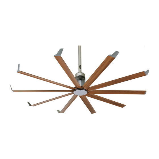
  • Page 64: Schéma Du Ventilateur

    D. Pale aérodynamique. Assure la ventilation. Grâce à son design breveté unique, l'air est mis en mouvement de manière et efficace et performante. E. Winglet. Améliore l'efficacité du ventilateur. Les winglets sont fournies de série sur les ventilateurs Isis ; des bouts de pales sont ®...
  • Page 65: Préparation Du Chantier

    Isis ® Avant l'installation (suite) Préparation du chantier Ce ventilateur doit obligatoirement être installé conformément aux instructions fournies dans ce manuel. Consultez un ingénieur-architecte pour connaître les techniques de montage non abordées dans ce manuel. Pour toute autre technique de montage, reportez-vous aux instructions fournies avec les composants du ventilateur.
  • Page 66 Notes...
  • Page 67: Structure D'ancrage : Poutrelles

    Isis ® Structure d'ancrage : poutrelles AVERTISSEMENT : Le ventilateur peut peser jusqu'à 54,4 kg (120 lb). Avant de procéder à l'installation du ventilateur, assurez-vous que la structure à laquelle il doit être fixé est saine, en parfait état et capable de supporter les charges du ventilateur ainsi que son mode d'ancrage.
  • Page 68: Structure D'ancrage : Poutrelles (Suite)

    Isis ® Structure d'ancrage : poutrelles (suite) 2. Pré-perçage des cornières métalliques Percez deux trous de 1,1 cm (7/16 po) de diamètre à exactement 14 cm (5-1/2 po) d'écart, au centre de deux cornières métalliques. Mesurez la distance séparant les points d'ancrage de la charpente ; cette distance correspondra à la portée des cornières métalliques.
  • Page 69: 4A. Fixation De Cornières Métalliques Simples Aux Points D'ancrage De La Charpente

    Isis ® Structure d'ancrage : poutrelles (suite) 4a. Fixation de cornières métalliques simples aux points d'ancrage de la charpente Si votre installation requiert l'utilisation de cornières métalliques doubles, à savoir si la portée est supérieure à 2,4 m (8 pi), passez à l'étape 4b.
  • Page 70: 4B. Fixation De Cornières Métalliques Doubles Aux Points D'ancrage De La Charpente

    Isis ® Structure d'ancrage : poutrelles (suite) 4b. Fixation de cornières métalliques doubles aux points d'ancrage de la charpente ATTENTION : Les cornières métalliques doivent être fixées à la charpente en chacune de leurs extrémités. Fixez les cornières métalliques aux points d'ancrage de la charpente à chacune de leurs extrémités, en utilisant la visserie de qualité 8 fournie par le client, comme illustré...
  • Page 71: Fixation Du Système De Fixation Supérieur (Sur Des Cornières Métalliques)

    Isis ® Structure d'ancrage : poutrelles (suite) 5. Fixation du système de fixation supérieur (sur des cornières métalliques) Fixez directement le système de fixation supérieur aux cornières métalliques à l'aide de la visserie prévue à cet effet, comme illustré ci-dessous. Reportez-vous aux schémas ci-dessous pour connaître les distances à respecter entre les cornières métalliques. Serrez la visserie à...
  • Page 72: Structure D'ancrage : Charpente En Bois

    Isis ® Structure d'ancrage : charpente en bois Les profilés en U pour charpente bois sont principalement utilisés dans les bâtiments à usage d’habitation. Nous vous invitons à consulter un ingénieur-architecte afin de vous assurer que vous avez choisi la technique de montage adaptée à...
  • Page 73: 2B. Fixation Des Supports (Sur Des Solives De Plancher)

    Isis ® Structure d'ancrage : charpente en bois (suite) 2b. Fixation des supports (sur des solives de plancher) Remarque : cette technique doit être utilisée lorsque le haut des solives est inaccessible. Fixez les supports aux points d'ancrage des solives de plancher à l'aide de la visserie pour charpente bois. Serrez la visserie à un couple de 33,9 N·m (25 pi·lb).
  • Page 74: Structure D'ancrage : Charpente En Bois (Suite)

    Isis ® Structure d'ancrage : charpente en bois (suite) 3. Fixation du système de fixation supérieur (sur des profilés en U pour charpente bois) Lors de la découpe des profilés en U pour charpente bois, veillez à ce que les trous situés à chaque extrémité soient alignés sur ceux des supports de fixation !
  • Page 75: Fixation Des Des Profilés En U Pour Charpente Bois (Aux Supports)

    Isis ® Structure d'ancrage : charpente en bois (suite) 4. Fixation des des profilés en U pour charpente bois (aux supports) ATTENTION : La distance de centre à centre entre les deux poutres ou solives entre lesquelles le ventilateur doit être suspendu ne doit pas être supérieure à...
  • Page 76: Structure D'ancrage : Poutre Pleine

    Isis ® Structure d'ancrage : poutre pleine Les équerres permettent de fixer le ventilateur à une poutre pleine. Nous vous invitons à consulter un ingénieur- architecte afin de vous assurer que vous avez choisi la technique de montage adaptée à la structure votre bâtiment.
  • Page 77: 3A. Fixation Des Équerres (Sur La Structure D'ancrage)

    Isis ® Structure d'ancrage : poutre pleine (suite) 3a. Fixation des équerres (sur la structure d'ancrage) Fixez les équerres à la structure d'ancrage à l'aide de la visserie pour équerres M12 ou 1/2-13 fournie par le client, comme illustré ci- dessous.
  • Page 78: Suspension Du Ventilateur

    Isis ® Suspension du ventilateur 1. Fixation de la tige de prolongation (au système de fixation supérieur) Faites passer l'élingue de sécurité, qui est fixée à la tige de prolongation, à travers le système de fixation supérieur, puis fixez la tige de prolongation au système de fixation supérieur (qui est déjà...
  • Page 79: Suspension Du Ventilateur (Suite)

    Isis ® Suspension du ventilateur (suite) 2c. Fixation de l'élingue de sécurité (à une poutre pleine) AVERTISSEMENT : L'élingue de sécurité est une pièce essentielle du ventilateur. Elle doit être mise en place correctement. Si vous avez la moindre question, veuillez contacter le service à...
  • Page 80: Mise En Place Des

    Isis ® Mise en place des haubans Il se peut que votre commande ne comporte pas de haubans. Ceux-ci sont destinés à limiter les mouvements latéraux du ventilateur et ne sont fournis qu'avec les commandes dans lesquelles la tige de prolongation mesure 1,2 m (4 pi) ou plus.
  • Page 81: Mise En Place Des Mousquetons De Sécurité Sur Les Attaches Pour Haubans

    Isis ® Mise en place des haubans (suite) 2. Mise en place des mousquetons de sécurité sur les attaches pour haubans Fixez les quatre (4) mousquetons de sécurité aux attaches pour haubans, comme illustré ci-contre. Serrez bien les mousquetons. 3a. Fixation de l'attache-poutre (montage sur poutrelle) Le hauban doit former un angle de 45°...
  • Page 82: Passage Du Hauban Dans Le Tendeur Gripple

    Isis ® Mise en place des haubans (suite) 4. Passage du hauban dans le tendeur Gripple ® Faites passer le hauban dans le tendeur Gripple, puis dans le mousqueton fixé sur l'attache pour haubans, avant de le faire repasser dans le tendeur Gripple, comme illustré...
  • Page 83: Montage Des Pales

    AVERTISSEMENT : Coupez l'alimentation du ventilateur avant de monter les pales aérodynamiques. 1. Fixation des winglets ou des bouts de pale (aux pales aérodynamiques) Remarque : les winglets sont fournies de série sur les ventilateurs Isis ; des bouts de pales sont néanmoins disponibles en option.
  • Page 84: Fixation Des Pales Aérodynamiques (Au Corps Du Ventilateur)

    Isis ® Mise en place des pales aérodynamiques (suite) 3. Fixation des pales aérodynamiques (au corps du ventilateur) Une fois le ventilateur entièrement assemblé et solidement accroché à la structure d'ancrage, ôtez le film en plastique recouvrant la partie inférieure du moyeu.
  • Page 85: Installation Électrique

    ATTENTION : N'installez JAMAIS ce ventilateur à un endroit où il pourrait entrer en contact direct avec l'eau, sauf s'il porte la mention « Suitable for use in wet locations » (appareil utilisable dans les lieux humides). Caractéristiques électriques 110–125 V CA Isis (intérieur) Caractéristiques minimales Intensité...
  • Page 86: Raccordement D'un Seul Ventilateur

    Isis ® Installation électrique (suite) Raccordement d'un seul ventilateur Un interrupteur mural est fourni seulement avec les ventilateurs vendus aux États-Unis, au Canada et en Arabie Saoudite. Les clients des autres pays doivent se procurer un variateur de lumière spécifique aux charges incandescentes.
  • Page 87: Raccordement De Plusieurs Ventilateurs

    Isis ® Installation électrique (suite) Raccordement de plusieurs ventilateurs Un interrupteur mural est fourni seulement avec les ventilateurs vendus aux États-Unis, au Canada et en Arabie Saoudite. Les clients des autres pays doivent se procurer un variateur de lumière spécifique aux charges incandescentes.
  • Page 88: Installation Du Dispositif De Commande Mural

    Isis ® Installation électrique (suite) Installation du dispositif de commande mural Un interrupteur mural est fourni seulement avec les ventilateurs vendus aux États-Unis, au Canada et en Arabie Saoudite. Les clients des autres pays doivent se procurer un variateur de lumière spécifique aux charges incandescentes.
  • Page 89: Utilisation Du Ventilateur

    Isis ® Utilisation du ventilateur Pour mettre le ventilateur en marche, appuyez une fois sur la partie supérieure du bouton-poussoir. Le ventilateur peut mettre jusqu’à 30 secondes avant de commencer à tourner. Pour arrêter le ventilateur, appuyez une fois sur la partie inférieure du bouton- poussoir.
  • Page 90: Inversion Du Sens De Rotation Du Ventilateur

    Isis ® Utilisation du ventilateur (suite) Inversion du sens de rotation du ventilateur ATTENTION : En manipulant le sélecteur de sens de rotation, veillez à ne pas endommager les composants internes ! ATTENTION : N'introduisez pas de corps étrangers dans le sélecteur de sens de rotation.
  • Page 91: Autres Techniques De

    BOÎTE D'INTERRUPTEUR MURALE EXISTANTE fonctionnement du ventilateur est absent. Lorsqu'il est difficile ou impossible de monter un ventilateur Isis ® un circuit 3 fils + terre (noir, blanc et rouge), un système de commande à accès restreint disponible en option peut être installé...
  • Page 92: Autres Techniques De Raccordement (Suite)

    Isis ® Autres techniques de raccordement (suite) Fonctionnement du système de commande à accès restreint avec commande à distance Pour plus de commodité, les jeux de dispositifs de commande muraux et télécommandés sont appariés en usine par Big Ass Fan.
  • Page 93: Va-Et-Vient Pour Un Seul Ventilateur

    Isis ® Autres techniques de raccordement (suite) Va-et-vient pour un seul ventilateur ATTENTION : Le ventilateur doit être branché sur un circuit dédié avec un fil neutre dédié. Si le ventilateur n’est pas branché sur un circuit dédié, il se peut qu’il ne fonctionne pas correctement.
  • Page 94: Maintenance Préventive Annuelle

    Isis ® Maintenance préventive AVERTISSEMENT : Avant toute intervention d'entretien ou de nettoyage, coupez le courant au niveau du tableau de distribution et verrouillez le sectionneur de maintenance afin d'empêcher toute remise sous tension accidentelle au cours de l'intervention. Lorsque le sectionneur de maintenance ne peut pas être verrouillé, fixez solidement et bien en vue, sur le tableau de distribution, un moyen d'avertissement tel qu'une étiquette.
  • Page 95: Liste De Contrôle Des Opérations De Maintenance Annuelle

    Isis ® Liste de contrôle des opérations de maintenance annuelle Modèle du ventilateur : Modèle du ventilateur : Modèle du ventilateur : Numéro de série : Numéro de série : Numéro de série : Emplacement : Emplacement : Emplacement :...
  • Page 97: Dépannage

    Isis ® Dépannage AVERTISSEMENT : Lorsque l'entretien ou le remplacement d'un composant du ventilateur nécessite la dépose ou la désactivation d'un dispositif de sécurité, ce dispositif doit être reposé ou réactivé dans l'état où il se trouvait avant l'intervention. ATTENTION : N'utilisez pas cet appareil pour un autre usage que celui prévu par le fabricant. Contactez le fabricant si vous avez la moindre question.
  • Page 98: Dépannage (Suite)

    Isis ® Dépannage (suite) Remplacement des fusibles AVERTISSEMENT : Vérifiez que le courant est coupé avant de remplacer les fusibles. Pour remplacer les fusibles sur le corps du ventilateur, ôtez la vis de fixation du couvre-fusible. Remplacez le ou les fusibles endommagés, puis remettez le couvre-fusible en place.
  • Page 99: Nous Contacter

    40150 Shah Alam, Selangor, Malaisie (+603) 5565 0888 Fabrication et garantie Vous êtes responsable de payer l'expédition pour le retour d'un équipement à Big Ass Fans aux fins de recyclage en vertu de la directive DEEE. Fabricant Procédures de garantie...
  • Page 104 004169-01 Rev. I 04/16/2020 2251 Innovation Drive, Lexington, KY 40511 1 (877) BIG-FANS | WWW.BIGASSFANS.COM...

Table des Matières