Table des Matières
Publicité
Liens rapides
sauder.com
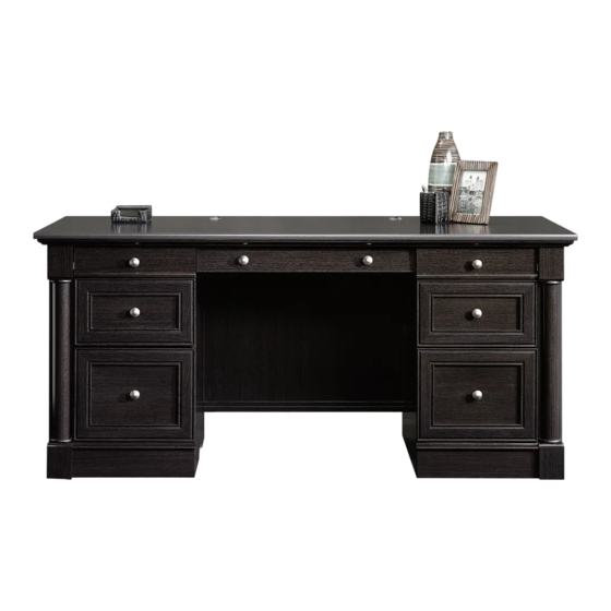
Executive Desk
Avenue Eight Collection | 416513
Need help? Visit Sauder.com to view video assembly tips or chat with a live rep.
Prefer the phone? Call 1-800-523-3987.
Share your journey!
Get executive
with this decision.
NOTE: THIS INSTRUCTION
BOOKLET CONTAINS IMPORTANT
SAFETY INFORMATION.
PLEASE READ AND KEEP FOR
FUTURE REFERENCE.
English pg 1-40
Français pg 41-46
Español pg 47-52
Lot # 372696
05/19/15
Purchased: __________________
Be sure to give us a ring before
making any returns. 1-800-523-3987
Publicité
Table des Matières

Manuels Connexes pour Sauder Avenue Eight Executive Desk 416513

Sommaire des Matières pour Sauder Avenue Eight Executive Desk 416513
- Page 1 Avenue Eight Collection | 416513 NOTE: THIS INSTRUCTION BOOKLET CONTAINS IMPORTANT SAFETY INFORMATION. Need help? Visit Sauder.com to view video assembly tips or chat with a live rep. PLEASE READ AND KEEP FOR FUTURE REFERENCE. Prefer the phone? Call 1-800-523-3987.
- Page 2 DRAWER BACK (2) RIGHT DRAWER SIDE (2) SKIRT (4) PLINTH (8) RIGHT BOTTOM MOLDING (2) KEYBOARD FRONT (1) LEFT DRAWER SIDE (2) TOP FRONT MOLDING (1) KEYBOARD BACK (1) SMALL RIGHT DRAWER FRONT (1) HALF DISK (8) Page 2 416513 www.sauder.com/services...
-
Page 3: Part Identifi Cation
Now you know Part Identifi cation our ABCs. www.sauder.com/services 416513 Page 3... - Page 4 Now you know Part Identifi cation our ABCs. D716 D716 D716 D708 D716 D708 Page 4 416513 www.sauder.com/services...
- Page 5 (EXTENSION SET SHOWN SEPARATED) WIDE WIDE FILE GLIDE - 4 FILE ROD - 4 EXTENSION RAIL - 4 EXTENSION SLIDE - 4 7F TWIST-LOCK HIDDEN CAM - 8 CAM DOWEL - 8 ® FASTENER - 25 www.sauder.com/services 416513 Page 5...
- Page 6 FRONT BRACKET - 4 14H HINGE - 2 KEYBOARD HINGE - 2 KNOB - 8 FELT DISC CARD - 1 GROMMET CAP - 2 CORD CLIP - 1 GROMMET - 3 RUBBER SLEEVE - 4 METAL PIN - 8 Page 6 416513 www.sauder.com/services...
-
Page 7: Table Des Matières
SILVER 5/8" FLAT HEAD SCREW - 4 30S BLACK 1-9/16" FLAT HEAD SCREW - 24 SILVER 1-1/4" MACHINE SCREW - 4 BLACK 7/8" MACHINE SCREW - 4 SILVER 9/16" LARGE HEAD SCREW - 2 100S BLACK 2-3/4" FLAT HEAD SCREW - 3 www.sauder.com/services 416513 Page 7... - Page 8 fl oor. Scan this QR code or go to this address: http://qr.sauder.com/?ID=1167 To begin assembly, push a SAUDER TWIST-LOCK® to watch a video on how to assemble your unit. å FASTENER (7F) into the large holes in the OUTER ENDS (A).
- Page 9 Then, insert the metal end of a CAM DOWEL (2F) into each HIDDEN CAM. Do not tighten the HIDDEN CAMS in this step. Arrow (8 used) Arrow Arrow Insert the metal end of the CAM DOWEL into the HIDDEN CAM. www.sauder.com/services 416513 Page 9...
- Page 10 fi nd the other hole that lines up with the hole in the END and UPRIGHT. Turn a SCREW into this hole. Push the release lever in and pull the SLIDE from the RAIL. Open end Open end Open end Open end Page 10 416513 www.sauder.com/services...
- Page 11 Push the black lever in and pull the SLIDE from the RAIL. Open end GOLD 5/16" FLAT HEAD SCREW (12 used in this step) Open end Open end (4 used) Open end BLACK 9/16" LARGE HEAD SCREW (4 used for the ANGLE BRACKETS) www.sauder.com/services 416513 Page 11...
- Page 12 FLAT HEAD SCREWS (3S). NOTE: The CABINET RAILS are marked "CABINET å RIGHT" and "CABINET LEFT" for easy identifi cation. Roller end GOLD 5/16" FLAT HEAD SCREW (4 used in this step) These holes must be here. Roller end Page 12 416513 www.sauder.com/services...
- Page 13 Tap four MOLDING CONNECTORS (17F) into the notches å in the TOP MOLDINGS (LL and UU) and SIDE MOLDINGS (NN). Use your hammer to tap the MOLDING CONNECTORS (17F) into the notches in the MOLDINGS. Flat end Flat end www.sauder.com/services 416513 Page 13...
- Page 14 MOLDINGS (NN) to the TOP (F). Use sixteen BLACK 1-1/4" FLAT HEAD SCREWS (7S). BLACK 1-1/4" FLAT HEAD SCREW (16 used in this step) The TOP REAR MOLDING (LL) has more holes. The large holes must be here. Page 14 416513 www.sauder.com/services...
- Page 15 Fasten the UPPER BACK MOLDING (MM) to the TOP å REAR MOLDING (LL) on the TOP (F). Tighten three TWIST-LOCK® FASTENERS. ® How to use the SAUDER TWIST-LOCK FASTENER Edge and surface with 1. Insert the dowel end of the FASTENER into the TWIST-LOCK® FASTENERS hole of the adjoining part.
- Page 16 OUTER ENDS. The larger hole should be facing up. BROWN 1" FLAT HEAD SCREW (8 used in this step) (20 used) BLACK 9/16" LARGE HEAD SCREW (20 used for the ANGLE BRACKETS) Page 16 416513 www.sauder.com/services...
- Page 17 MOLDINGS (NN) on the TOP (F). Tighten four TWIST-LOCK® FASTENERS. r f a I S T w i t - L O ® r f a I S T w i t - L O ® www.sauder.com/services 416513 Page 17...
- Page 18 These holes must be here. Use outer holes Use outer holes BLACK 9/16" LARGE HEAD SCREW (20 used for the ANGLE BRACKETS) Use outer holes The MOLDING (M35) should be centered over the HALF DISK (VV). Page 18 416513 www.sauder.com/services...
- Page 19 Fasten the ENDS (B and C) to the TOP (F). Tighten four å TWIST-LOCK® FASTENERS. Open end r f a I S T w i t - L O ® r f a I S T w i t - L O ® Open end www.sauder.com/services 416513 Page 19...
-
Page 20: Black 1-7/8" Flat Head Screw
BACK (J) into the holes in the LEFT END (C). The large holes must be here. BLACK 1-7/8" FLAT HEAD SCREW (4 used in this step) n i s h U n fi f a c s u r (4 used) Page 20 416513 www.sauder.com/services... - Page 21 BLACK 9/16" LARGE HEAD SCREW (4 used in this step) r f a I S T w i t - L O ® r f a I S T w i t - L O Roller end ® Open end www.sauder.com/services 416513 Page 21...
- Page 22 Push the CORD CLIP (9P) into the hole in the TOP (F). å Unfi nished surface NOTE: The CORD CLIP is used to manage your cords. å 100S Rounded edge Curved edge BLACK 1-7/8" FLAT HEAD SCREW (4 used for the UPRIGHTS) Page 22 416513 www.sauder.com/services...
- Page 23 Tighten Risk of damage or Arrow injury. HIDDEN CAMS must be completely Arrow Maximum tightened. HIDDEN 210 degrees CAMS that are not completely tightened may loosen, and parts may separate. To Minimum completely tighten: 190 degrees www.sauder.com/services 416513 Page 23...
-
Page 24: Black 9/16" Large Head Screw
Fasten the BRACES (K) to the OUTER ENDS (A), å UPRIGHTS (D and E), and BOTTOMS (G). Use eight BLACK 9/16" LARGE HEAD SCREWS (1S). BLACK 9/16" LARGE HEAD SCREW (16 used for the ANGLE BRACKETS) Page 24 416513 www.sauder.com/services... - Page 25 Fasten the BRACES (K) to the OUTER ENDS (A), å UPRIGHTS (D and E), and BOTTOMS (G). Use eight BLACK 9/16" LARGE HEAD SCREWS (1S). BLACK 9/16" LARGE HEAD SCREW (16 used for the ANGLE BRACKETS) www.sauder.com/services 416513 Page 25...
-
Page 26: Black 1-1/4" Flat Head Screw
Use twenty-four BLACK 1-1/4" FLAT HEAD SCREWS (7S). BLACK 1-1/4" FLAT HEAD SCREW (24 used in this step) Use outer holes Finished edge Edge without HALF DISK Edge without HALF DISK Use outer holes Finished edge Edge without HALF DISK Page 26 416513 www.sauder.com/services... -
Page 27: Black 1/2" Flat Head Screw
Step 20 Fasten the HINGES (14H) to the DOOR (L). Use four å BLACK 1/2" FLAT HEAD SCREWS (11S). BLACK 1/2" FLAT HEAD SCREW (4 used in this step) www.sauder.com/services 416513 Page 27... - Page 28 PINS (1R). Insert the METAL PINS into the hole locations of your choice in the LEFT END (C) and LEFT UPRIGHT (E). Set the ADJUSTABLE SHELF (M) onto the METAL PINS. Hinge Insert a GROMMET (10P) into the large hole in å the BOTTOM (G). (4 used) Page 28 416513 www.sauder.com/services...
- Page 29 Tighten the screws after making adjustments. (vertical adjustment) To adjust the DOOR in or out (depth), loosen the mounting å screw one turn and move the DOOR in or out, as needed. Tighten the mounting screw after making adjustments. www.sauder.com/services 416513 Page 29...
- Page 30 Use two BLACK 1-1/4" FLAT HEAD SCREWS (7S). Finished edge Finished surface Short fi nished edge BLACK 1-1/4" FLAT HEAD SCREW (6 used in this step) Finished edge These holes must be here. Short fi nished edge Page 30 416513 www.sauder.com/services...
-
Page 31: Silver 5/8" Flat Head Screw
Fasten the KEYBOARD HINGES (12H) to the KEYBOARD SHELF (R). å Use two SILVER 9/16" LARGE HEAD SCREWS (54S). SILVER 5/8" FLAT HEAD SCREW SILVER 9/16" LARGE HEAD SCREW (4 used in this step) (2 used in this step) www.sauder.com/services 416513 Page 31... -
Page 32: Brown 1" Flat Head Screw
Fasten two KNOBS (42K) to the KEYBOARD FRONT (O). å Use two BLACK 7/8" MACHINE SCREWS (37S). Roller end BLACK 7/8" MACHINE SCREW (2 used for the KNOBS) Roller end BROWN 1" FLAT HEAD SCREW (4 used for the DRAWER SLIDES) Page 32 416513 www.sauder.com/services... -
Page 33: Black 2-3/4" Flat Head Screw
Be sure the grooves in each part line up with each other on the inside of the drawer. Use top hole Groove Groove Use top hole BLACK 1-9/16" FLAT HEAD SCREW (16 used in this step) Groove www.sauder.com/services 416513 Page 33... - Page 34 Slide the DRAWER BOTTOMS (D708 and D716) into the grooves å in the DRAWER SIDES (D33, D32, D34, D35, D36, and D37) and DRAWER BACKS (D78, D77, and D74). Repeat this step for the other drawers. å D716 D716 D708 Page 34 416513 www.sauder.com/services...
- Page 35 PAN HEAD SCREWS (9S). Repeat this step for the other drawers using å the LEFT DRAWER FRONTS (BB and GG). BLACK 1-1/8" PAN HEAD SCREW (8 used for the DRAWER FRONTS) These edges should be even. www.sauder.com/services 416513 Page 35...
- Page 36 (2 used for the KNOBS on the DRAWERS) t e n r r o Open end l i d r r o s i o t e n GOLD 5/16" FLAT HEAD SCREW (8 used in the fi rst hole in the SLIDES) Page 36 416513 www.sauder.com/services...
- Page 37 Repeat this step for the other large drawer using the å LARGE LEFT DRAWER FRONT (U). BLACK 9/16" LARGE HEAD SCREW (8 used for the BRACKETS) BLACK 1-1/8" PAN HEAD SCREW (8 used for the DRAWER FRONTS) These edges should be even. www.sauder.com/services 416513 Page 37...
- Page 38 Open end (2 used for the KNOBS) l i d s i o t e n Open end l i d s i o t e n GOLD 5/16" FLAT HEAD SCREW (8 used in this step) Page 38 416513 www.sauder.com/services...
- Page 39 FILE RODS (8B), then press this FILE GLIDE over the LARGE LEFT DRAWER SIDE (D32). Repeat this step for the other large drawer. å Insert the FILE RODS into the holes of your choice in the FILE GLIDES, depending on your fi le sizes. www.sauder.com/services 416513 Page 39...
- Page 40 This completes assembly. Clean with your favorite furniture polish or a damp cloth. Wipe dry. å And to celebrate, why not share your success story? 10 lbs. 75 lbs. 20 lbs. 15 lbs. 15 lbs. each 30 lbs. 10 lbs. 30 lbs. Page 40 416513 www.sauder.com/services...
-
Page 41: Bureau Ministre
élément et conserver le livret pour future référence. EXTRÉMITÉ EXTERNE ..........2 D708 FOND DE GRAND TIROIR ........2 Pour contacter Sauder EXTRÉMITÉ DROITE ..........1 DEVANT DE CAISSON DE TIROIR ....2 en ce qui concerne cet EXTRÉMITÉ GAUCHE ..........1 DEVANT DE TIROIR DROIT ........1... - Page 42 12H CHARNIÈRE DE TABLETTE DE CLAVIER ..............2 14H CHARNIÈRE ..............2 42K BOUTON ................8 FICHE DE TAMPONS EN FEUTRE....1 COUVERCLE DE PASSE-CÂBLES ....2 CLIP POUR CORDONS ...........1 PASSE-CÂBLES ............3 GOUPILLE EN MÉTAL ..........8 MANCHON EN CAOUTCHOUC .....4 Page 42 416513 www.sauder.com/services...
- Page 43 Pour commencer l'assemblage, enfoncer une FIXATION EXTRÉMITÉS et les MONTANTS. Faire tourner une VIS dans ce trou. TWIST-LOCK® SAUDER (7F) dans les gros trous des Fixer quatre CONSOLES À ÉQUERRE (27G) à l'EXTRÉMITÉ EXTRÉMITÉS EXTERNES (A).
- Page 44 14 mm NOIRES (1S) à travers les CONSOLES EN MÉTAL sur la Fixer les ENTRETOISES (K) aux EXTRÉMITÉS EXTERNES (A), MOULURE ARRIÈRE SUPÉRIEURE et dans les MONTANTS. MONTANTS (D et E) et DESSOUS (G). Utiliser huit VIS NOIRES TÊTE LARGE 14 mm (1S). Page 44 416513 www.sauder.com/services...
- Page 45 Serrer les vis après avoir ajusté. Pour ajuster la PORTE vers l'intérieur où vers l'extérieur (profondeur), desserrer la vis de montage un tour et déplacer la PORTE vers l'intérieur ou vers l'extérieur. Serrer la vis de après avoir ajusté. www.sauder.com/services 416513 Page 45...
- Page 46 Fixer le DEVANT DROIT DE GRAND TIROIR (T) au DEVANT DE CAISSON DU GRAND TIROIR (S). Utiliser quatre VIS NOIRES TÊTE GOUTTE DE SUIF 28 mm (9S). Répéter cette étape pour l'autre grand tiroir en utilisant le DEVANT GAUCHE DE GRAND TIROIR (U). Page 46 416513 www.sauder.com/services...
- Page 47 CARA DERECHA DE CAJÓN ....... 1 et conserver le livret EXTREMO DERECHO ..........1 CARA IZQUIERDA DE CAJÓN ......1 pour future référence. Pour contacter Sauder EXTREMO IZQUIERDO ..........1 D77 DORSO DE CAJÓN ............. 2 en ce qui concerne cet PARAL DERECHO ............1 BASE ..................8...
-
Page 48: Lista De Partes
12H BISAGRA DE ESTANTE DE TECLADO ..2 BISAGRA ................2 42K POMO ..................8 TARJETA CON TOPES DE FIELTRO ....1 CUBIERTA DE OJAL ............ 2 GRAPA DEL CABLE ............. 1 10P OJAL..................3 ESPIGA DE METAL ............8 MANGUITO DE GOMA ..........4 Page 48 416513 www.sauder.com/services... - Page 49 Fije cuatro SOPORTES ANGULARES (27G) al EXTREMO DERECHO (B) y Para comenzar el ensamblaje, empuje un SUJETADOR al PARAL DERECHO (D). Utilice cuatro TORNILLOS NEGROS DE CABEZA TWIST-LOCK® SAUDER (7F) dentro de los agujeros grandes GRANDE de 14 mm (1S). de los EXTREMOS EXTERIORES (A).
- Page 50 CABEZA GRANDE de 14 mm (1S) por entre los SOPORTES DE PARALES (D y E) y a los FONDOS (G). Utilice ocho TORNILLOS METAL en la MOLDURA POSTERIOR SUPERIOR y por entre NEGROS DE CABEZA GRANDE de 14 mm (1S). los PARALES. Page 50 416513 www.sauder.com/services...
- Page 51 Para ajustar la PUERTA hacia atrás o hacia adelante (profundidad), afl oje el tornillo de montaje una vuelta y mueva la PUERTA hacia el interior o hacia el exterior según sea necesario. Apriete el tornillo de montaje después de hacer los ajustes. www.sauder.com/services 416513 Page 51...
- Page 52 Fije la CARA DERECHA DE CAJÓN GRANDE (T) al FRENTE DE CAJÓN GRANDE (S). Utilice cuatro TORNILLOS NEGROS DE CABEZA REDONDA de 28 mm (9S). Repita este paso para el otro cajón grande utilizando la CARA IZQUIERDA DE CAJÓN GRANDE (U). Page 52 416513 www.sauder.com/services...
- Page 53 à Les téléviseurs peuvent être particulièrement un téléviseur. cet eff et. lourds. De plus, le poids et l’emplacement du tube image ont tendance à rendre les téléviseurs instables et enclins à tomber vers l’ a vant. www.sauder.com/services 416513 Page 53...
- Page 54 Además, el peso y la ubicación del tubo de imagen tienden a causar la inestabilidad de televisores y propensa a volcarse hacia adelante. Page 54 416513 www.sauder.com/services...
-
Page 55: Garantie Limitée De 5 Ans
GARANTIE LIMITÉE DE 5 ANS 1. Sauder Woodworking Co. (Sauder®) off re une couverture de garantie limitée à l’ a cheteur 4. La présente garantie ne s’ a pplique qu’ a ux défauts garantis qui se produisent pour initial du présent produit pendant une période de cinq ans à... - Page 56 Dear Valued Customer: So, how did it go? Thanks so much for choosing Sauder® furniture. I hope the Set a world record for speed? purchase and assembly process was a positive experience Feeling good about yourself? and you feel good about the furniture you just built. If you Nice.