Table des Matières
Publicité
Liens rapides
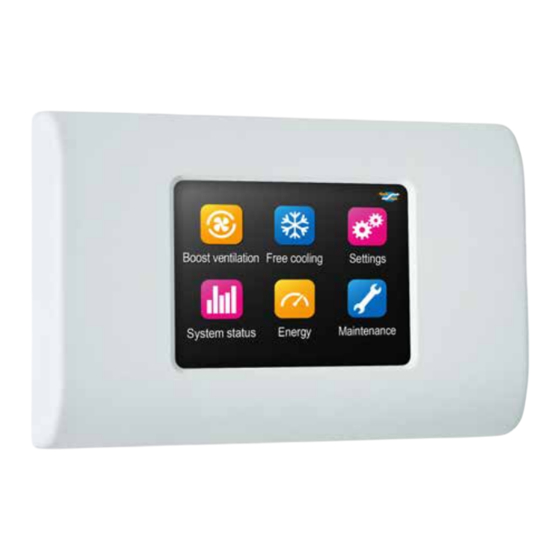
XP-1 Excellence mit DX Hub 5 (Bedarfsgeführte Wohnungslüftung mit Wärmerückgewinnung) Grafik-Display
DXR 170 Excellence with DX Hub 5 (Room-by-room demand control heat recovery) Graphic interface
DXR 170 Excellence avec DX Hub 5 (double flux modulé avec récupération de chaleur) Interface graphique
Hauptfunktionen:
• Systemstart
• Intensivlüftung und Kühlung
• Systemparameter
• Betriebs- und Leistungsdaten
• Wartung
17/05/2017
TF5821_E
Main functions:
• Starting the system
• Boost ventilation and free cooling
• System settings
• Operating and performance
• Maintenance
MONTAGE UND BEDIENUNG
INSTALLATION AND USE
INSTALLATION ET UTILISATION
Fonctions principales :
• Démarrage du système
• Surventilation et rafraîchissement
• Paramètres du système
• Fonctionnement et performances
• Maintenance
(DE)
(EN)
(FR)
Publicité
Table des Matières

Manuels Connexes pour Aereco XP-1

Sommaire des Matières pour Aereco XP-1
- Page 1 INSTALLATION ET UTILISATION (FR) XP-1 Excellence mit DX Hub 5 (Bedarfsgeführte Wohnungslüftung mit Wärmerückgewinnung) Grafik-Display DXR 170 Excellence with DX Hub 5 (Room-by-room demand control heat recovery) Graphic interface DXR 170 Excellence avec DX Hub 5 (double flux modulé avec récupération de chaleur) Interface graphique...
-
Page 2: Table Des Matières
2 / 42 1. Einführung 2. Piktogramme Präsentation der raumweisen bedarfsgeführten Wohnungslüftung DXR 3. PIktogramme 4. Allgemeiner Betrieb 4.1. Hauptmenü 4.2. Aufbau des Bildschirms und Navigation zwischen den verschiedenen Menüs 4.3. Standby 5. Initialisierung 5.1. Grafik-Display Anschließen 5.2. Sprachwahl 5.3. Montagedatum 5.4. - Page 3 3 / 42 1. Introduction 1. Introduction 2. Presentation of the room by room demand control 2. Présentation du double flux modulé pièce par pièce DXR heat recovery 3. Pictogrammes 3. Pictograms 4. Fonctionnement général 4. General operation 4.1. Menu principal 4.1.
- Page 4 4 / 42 WARNHINWEISE: LESEN SIE BITTE DIE FOLG ENDEN ANWEISUNGEN VOR DEM EINBAU DURCH:: Bei Nichteinhaltung der in dieser Anleitung enthaltenen Ratschläge und Warnhinweise kann der Hersteller nicht für Personen- oder Sachschäden verantwortlich gemacht werden. Diese Anleitung beschreibt, wie das Gerät korrekt eingebaut, verwendet und gewartet wird.
-
Page 5: Avertissements
5 / 42 WARNINGS: AVERTISSEMENTS : PLEASE READ THE FOLLOWING INSTRUCTIONS VEUILLEZ LIRE LES INSTRUCTIONS SUIVANTES BEFORE THE APPLIANCE INSTALLATION: AVANT L’INSTALLATION DE L’APPAREIL : In case of non-compliance with advice and warnings contained in En cas de non-respect des conseils et des avertissements contenus this manual, the manufacturer can not be considered responsible for dans ce manuel, le fabricant ne peut pas être considéré... -
Page 6: Einführung
6 / 42 1. EINFÜHRUNG Herzlichen Glückwunsch, Sie haben sich für eine raumweise bedarfsgeführte Zu- und Abluftanlage XP-1 Excellence von Aereco entschieden. Mit Hilfe dieser Anlage gewährleisten Sie eine ständige optimale Innenraumluftqualität und sparen dabei noch an Energiekosten. Bitte lesen Sie diese Gebrauchsanweisung aufmerksam durch. -
Page 7: Présentation Du Double Flux Modulé Pièce Par Pièce Dxr
7 / 42 1. INTRODUCTION 1. INTRODUCTION You are the new owner of an Aereco DXR 170 Excellence: a heat- Vous venez d’acquérir le DXR 170 Excellence d’Aereco : un système recovery with room-by-room demand controlled airflow rate. This double flux à débits modulés pièce par pièce. Ce système va system will ensure good air quality in your dwelling at all times vous permettre d’assurer en permanence une bonne qualité... -
Page 8: Piktogramme
8 / 42 Alle Luftmengen werden in Abhängigkeit des Lüftungsbedarfs in jedem Raum der Wohnung automatisch angepasst: Zuluft in den Wohn- und Schlafräumen, Abluft in der Küche, Bad und WC. Die einzelnen Zuluftelemente sind direkt an die Luftverteilungsbox DX Hub angeschlossen. Die Luftverteilbox passt in jedem Wohn- und Schlafraum unter Einbeziehung der dort gemessenen, relativen CO -Konzentration oder erfassten Präsenz (E) die Zuluftmenge an. - Page 9 9 / 42 The air flow rates are automatically modulated according to the needs Les débits d’air sont automatiquement modulés en fonction des besoins of each room of the dwelling: both the air supplied to the bedrooms de chaque pièce du logement : à l’insufflation dans les chambres et and living room and the air exhausted from the kitchen, bathroom, and le séjour comme à...
-
Page 10: Allgemeiner Betrieb
10 / 42 4. ALLGEMEINER BETRIEB Das Grafik-Display ist ein Touchpad. Das heißt, man kann die gewünschten Vorgänge durch einfaches Antippen der Symbole auslösen. Um die Parameter für einen Vorgang anzeigen zu lassen, drückt man länger auf das betreffende Symbol (zum Beispiel beim Einstellen von Zeiträumen und Temperaturen). -
Page 11: General Operation
11 / 42 4. GENERAL OPERATION 4. FONCTIONNEMENT GÉNÉRAL The graphic interface uses a touch screen. Simply press one of L’interface graphique est tactile. Il suffit d’appuyer sur les the icons to trigger the desired action. A long press on an icon icônes pour déclencher les actions désirées. -
Page 12: Initialisierung
Das Touch-Display wird mit einem oder RJ12- Kabel an der Rückseite des Displays mit der DXR verbunden. Das RJ12-Kabel ist spezifisch für Aereco, bitte melden Sie sich an die Installationsanleitung für weitere Informationen. An der Rückseite des Gehäuses ist ein abtrennbarer Bereich als Kabeldurchlass vorgesehen. - Page 13 The graphic interface is connected to the DXR via an RJ12 cable on L’interface graphique est connectée au DXR via un câble RJ12 situé au the back of the interface. The RJ12 cable is specific to Aereco, please dos de l’interface. Le câble RJ12 est spécifique à Aereco, se reporter report to the installation guidance for more information.
-
Page 14: Vorerhitzer
Geben Sie an, ob eine Kondensatpumpe an das System angeschlossen ist. 5.8. ANZAHL DER ANGESCHLOSSENEN SENSOREN BESTIMMEN Bei diesem Menüpunkt wird die Anschlussqualität der mit RJ12-Kabeln (spezifische Aereco) verbundenen CO -Sensoren bzw. erfassten Präsenz angezeigt. Siehe Bild Geben Sie mit Hilfe der Symbole die Anzahl der an die DXR angeschlossenen Sensoren an und bestätigen Sie dann mit OK. - Page 15 This step serves to check the connection of the CO or presence sensors Cette étape permet de vérifier le raccordement des capteurs CO to the DXR via the RJ12 cables (specific to Aereco). présence au DXR via les câbles RJ12 (spécifique à Aereco). See figure...
-
Page 16: Zuordnung Der Sensoren Und Zuluftelemente
16 / 42 5.9. ZUORDNUNG DER SENSOREN UND ZULUFTELEMENTE Siehe Bild Bei diesem Schritt wird überprüft, dass die Zuordnung der Zulufträume mit dem jeweiligen CO -Sensoren bzw. erfassten Präsenz verbunden sind. Bei jedem Zwischenschritt geben Sie bitte ein, ob das markierte Element (blau, mit Nummer) ordentlich an das System angeschlossen ist und überprüfen Sie die Einstellung (Indexierung 1-5) der Sensoren. -
Page 17: Association Capteurs Et Bouches De Soufflage
17 / 42 5.9. PAIRING OF SENSORS AND SUPPLY UNITS 5.9. ASSOCIATION CAPTEURS ET BOUCHES DE SOUFFLAGE See figure Voir figure This step serves to check the pairing of the supply units with their CO Cette étape permet de vérifier l’association des bouches de soufflage or presence sensors. -
Page 18: Benutzermenü
18 / 42 6. BENUTZERMENÜ 6.1. INTENSIVLÜFTUNG Bei der Intensivlüftung wird die Lüftung für eine bestimmte Zeit mit höchster Luftmenge betrieben. Diese Betriebsart ist immer dann nützlich, wenn die Luft in der Wohnung rasch erneuert werden soll, zum Beispiel bei Bauarbeiten mit toxischen Substanzen. Allerdings sollte die Intensivlüftung nicht bei Bauarbeiten verwendet werden, bei der viel Staub gebildet wird (Gipsarbeiten, Schleifen usw.). -
Page 19: Menu Utilisateur
19 / 42 6. USER MENU 6. MENU UTILISATEUR 6.1. BOOST VENTILATION 6.1. SURVENTILATION Boost ventilation is an operating mode in which maximum air flow is La surventilation est un mode de fonctionnement permettant de forcer forced for a well-defined period of time. This can be useful to change les débits d’air au maximum pendant une période de temps bien définie. -
Page 20: Kühlung
20 / 42 6.2. KÜHLUNG Bei der Kühlung wird die Intensivlüftung automatisch eingeschaltet, sobald die Innen- und Außentemperaturen zur Kühlung der Wohnung geeignet sind. Wenn zum Beispiel im Sommer die Außentemperatur in der Nacht kühler ist als die Innentemperatur, ist es sinnvoll, die Frischluft direkt von Außen mit maximalen Volumenstrom zur Kühlung in die Wohnung einzutragen. -
Page 21: Free Cooling
21 / 42 6.2. FREE COOLING 6.2. RAFRAÎCHISSEMENT Free cooling is an operating mode that automatically activates boost Le rafraîchissement est un mode de fonctionnement permettant ventilation when the indoor and outdoor temperatures are right for cooling d’enclencher automatiquement la surventilation lorsque les conditions the dwelling. -
Page 22: Bypass
22 / 42 6.3. BYPASS Der Bypass ist eine automatische Funktion, die den Luftstrom am Wärmeübertrager vorbei leitet. Dank dieser Funktion wird vermieden, dass die Wohnung zum Beispiel in der Übergangszeit zu stark aufgeheizt wird, wenn wegen des Wärmeeintrags (z.B. Sonneneinstrahlung) die Innenraumtemperatur zu hoch ist. -
Page 23: Paramétrage Du Bypass
23 / 42 6.3. BYPASS 6.3. BYPASS Bypass is an automatic function in which the air flow does not go through Le bypass est une fonction automatique permettant aux flux d’air de ne the exchanger. This function serves to avoid overheating the dwelling, for pas passer par l’échangeur. -
Page 24: Statistische Betriebsdaten
24 / 42 6.4. STATISTISCHE BETRIEBSDATEN In diesem Menü werden die statistischen Betriebsdaten des Systems angeführt. Das Menü können Sie mit dem Symbol "Systemstatus" im Hauptmenü aufrufen Mehrere Systemparameter können angezeigt werden: · Gesamt-Zuluftmenge. · Zuluftdruck. · Zulufttemperatur. · Öffnung der Zuluftelemente. ·... -
Page 25: Statistiques De Fonctionnement
25 / 42 6.4. OPERATING STATISTICS 6.4. STATISTIQUES DE FONCTIONNEMENT This menu displays the operating statistics of the system. Ce menu permet de visualiser les statistiques de fonctionnement du système. To access the menu, press the “System status” icon of the main menu Pour accéder au menu, appuyer sur l’icône «... -
Page 26: Vorheizregister
26 / 42 6.4.3. VORHEIZREGISTER Siehe Bild Wenn Sie den Istwert des Vorheizregisters ansehen möchten, drücken Sie auf den entsprechenden Parametertext im Menü "Systemstatus". Der Istwert des Parameters wird auf dem Bildschirm angezeigt. Der angezeigte Wert gibt an, zu wie viel Prozent der Höchstleistung die Frischluft momentan vorgewärmt wird. -
Page 27: Performance Énergétique
27 / 42 6.4.3. DEFROSTING DEVICE 6.4.3. DISPOSITIF DE DÉGIVRAGE See figure Voir figure To look up the instantaneous power of the defrosting device, press Pour consulter la valeur instantanée du dispositif de dégivrage, appuyer the text corresponding to the desired parameter in the “System sur le texte correspondant au paramètre souhaité... -
Page 28: Zusätzliche Parameter
28 / 42 6.6. ZUSÄTZLICHE PARAMETER 6.6.1. SPRACHWAHL Die beim Initialisieren eingestellte Sprache kann hier geändert werden. Dazu klicken Sie auf das Symbol "Einstellungen" im Hauptmenü Drücken Sie auf "Sprache". Wählen Sie die Sprache, indem Sie auf das entsprechende Bild drücken. 6.6.2. -
Page 29: Additional Settings
29 / 42 6.6. ADDITIONAL SETTINGS 6.6. PARAMÈTRES SUPPLÉMENTAIRES 6.6.1. CHOICE OF LANGUAGE 6.6.1. CHOIX DE LA LANGUE It is possible to change from the language selected at the time of Il est possible de modifier la langue présélectionnée lors de initialization. -
Page 30: Verschmutzungsgrad Der Filter
30 / 42 6.7.2. VERSCHMUTZUNGSGRAD DER FILTER Siehe Bild Wenn Sie den Verschmutzungsgrad der Filter erfahren möchten, drücken Sie auf den entsprechenden Parametertext im Menü "Filterwechsel". Daraufhin erscheint der beim letzten Filtertest festgestellte Verschmutzungsgrad der Filter auf dem Bildschirm. Dieser Verschmutzungsgrad stellt die Differenz zwischen dem Istwert und dem max. -
Page 31: Taux D'encrassement Des Filtres
31 / 42 6.7.2. FILTERS CLOGGING 6.7.2. TAUX D'ENCRASSEMENT DES FILTRES See figure Voir figure The filters clogging rate can be looked up by pressing the text Le taux d’encrassement des filtres est consultable en appuyant corresponding to the desired parameter in the “Maintenance” menu. sur le texte correspondant au paramètre souhaité... -
Page 32: Sensor-Alarm
Sensoren nicht mehr findet. Das System zeigt die Nummer des/der betreffenden Sensor(en) an. In diesem Fall muss man den entsprechenden Sensor identifizieren und die elektrischen Anschlüsse (RJ-12 Leitung spezifische Aereco) sowohl am Sensor als auch an der Anschlussplatine der DXR und/ oderDX Hub überprüfen. -
Page 33: Alerte Capteurs
Find the corresponding sensor and check the connection to the Trouver le capteur correspondant et vérifier le branchement au niveau sensor (RJ 12 cable specific to Aereco) and to the DXR Unit or du capteur (câble RJ12 spécifique à Aereco), ainsi qu’au niveau des DX Hub. -
Page 34: Display Außer Spannung Setzen Und Rückstellen
Das Grafik-Display wird von der DXR direkt mit Spannung versorgt. Wenn das Display also außer Spannung gesetzt werden soll, muss man das RJ12-Kabel spezifische Aereco an der Rückseite abziehen (siehe Bild Eine andere Möglichkeit besteht darin, die DXR vom Stromnetz zu trennen, ggf. -
Page 35: Mise Hors Tension Et Réinitialisation De L'interface
The graphic interface is powered directly by the DXR. To power down L’interface graphique est directement alimentée par le DXR. Pour the interface, you can disconnect the RJ12 cable, specific to aereco, mettre l’interface hors tension, il est nécessaire de débrancher le on the back of the interface (See figure câble RJ12, spécifique Aereco, au dos de l’interface (Voir figure... -
Page 36: Fehlerbehebung
36 / 42 9. FEHLERBEHEBUNG Fehler Lösungsvorschlag (bitte in der vorgeschlagenen Reihenfolge durchgehen) Überprüfen Sie zuerst, ob das System auch ordentlich an die Stromversorgung angeschlossen ist. Das System startet nicht. Überprüfen Sie dann, dass alle Anschlusskabel ordentlich angeschlossen sind: Display,DX Hub, Abluft-Kompensationsventil (nichts startet, weder die Ventilatoren noch das Display). - Page 37 37 / 42 9. TROUBLESHOOTING Problem Proposed solution (the steps must be performed in the order indicated) Check that the system is correctly connected to the power supply. Check that the communication cables are correctly connected: Interface, DX Hub, Exhaust compensation valve. The system fails to start.
-
Page 38: Résolution Des Problèmes
38 / 42 9. RÉSOLUTION DES PROBLÈMES Problème Proposition de solution (les actions doivent être effectuées dans l’ordre indiqué) Vérifier que le système est correctement connecté à l'alimentation. Vérifier que les câbles de communication sont correctement branchés : Interface, DX Hub, Vanne de compensation à Le système ne démarre pas. -
Page 39: Garantie - Kundendienst - Konformität
Dokument eingeschlichen haben. Aereco kann nicht für die Zuverlässigkeit der Informationen, Unterlassungen oder fehlende Daten verantwortlich gemacht werden, die Schäden am Gerät rechtfertigen. Aereco behält sich das Recht vor, die Informationen in diesem Dokument ohne vorherige Ankündigung zu ändern, zu aktualisieren oder zu entfernen. Sämtliche Abbildungen und Inhalte dieser Unterlage sind Eigentum ihrer Autoren und dürfen ohne deren ausdrückliche Erlaubnis nicht reproduziert werden. -
Page 40: Warranty Conditions
The use of this interface for any other type of application is not authorized. Note: In spite of all our efforts to ensure the reliability of the data, there may be errors in this document. Aereco cannot be held liable for any damage to the appliance that results from the unreliability of the information communicated or from omissions or missing information. -
Page 41: Conditions De Garanties
à notre insu. Aereco ne pourrait être tenu responsable de la non fiabilité des informations communiquées, omissions ou informations manquantes pour justifier toute dégradation sur l’appareil. Aereco se réserve le droit de modifier, mettre à jour ou retirer toute information dans ce document sans préavis. - Page 42 Deutschland : Aereco GmbH Robert-Bosch-Straße 9 65719 Hofheim-Wallau DEUTSCHLAND Tel.: 06122/ 92 768 30 - Fax: 06122/ 92 768 90 www.aereco.de Other countries / Autres pays : Aereco S.A. 62 rue de Lamirault Collégien 77615 Marne-la-Vallée cedex 3 FRANCE Tel.: +33 1 60 06 44 65 - Fax: +33 1 64 80 47 26...