
Manuels Connexes pour YORKVILLE YS1011


Sommaire des Matières pour YORKVILLE YS1011
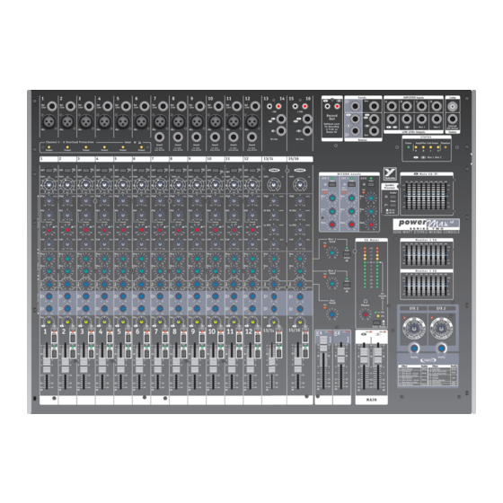
- Page 1 S E R I E S T W O 3200 WATT STEREO MIXING CONSOLE Model Type: YS1011 OWNER’S MANUAL MANUEL DE L’UTILISATEUR...
-
Page 2: Important Safety Instructions
IMPORTANT SAFETY INSTRUCTIONS This lightning flash with arrowhead symbol, within The exclamation point within an equilatereal triangle is an equilateral triangle, is intended to alert the user to intended to alert the user to the presence of important the presence of uninsulated “dangerous voltage” operating and maintenance (servicing) instructions in within the product’s enclosure that may be of sufficient the literature accompanying the appliance. - Page 3 PowerMAX users may be unfamiliar with certain features, we include user tips and addi- tional information, which appears separately in the applicable sections. For general information about mixing and other facets of sound-reinforcement check out our P.A. User Guide available on the internet... (http://www.yorkville.com).
- Page 4 Insert Insert Tip: SEND Tip: SEND Tip: SEND Tip: SEND Tip: SEND Tip: SEND Yorkville model PC-6iSPH) Ring: RETURN Ring: RETURN Ring: RETURN Ring: RETURN Ring: RETURN Ring: RETURN would consist of a single TRS (stereo) 1/4-inch plug and two lengths of shielded cable with a common ground branching to two regular (mono) 1/4-inch plugs.
- Page 5 4. Phantom Power Switch and LED Phantom Phones Phantom Power is available for condenser microphones. It may be applied to channels with regular dynamic microphones connected with no problems. When connecting micro- phones it is safest to turn off phantom power to avoid loud pops. The Phantom Power On/Off button is located on the front of the mixer, beside the Headphone jack and the Phantom Power LED is in the upper right area of the control panel.
-
Page 6: Gain Control
7. HPF Button Situated at the top of the mono channel strips, this switch activates a High-Pass Filter (a bass roll-off of 18 dB per octave below 80 Hz). The stereo channels do not have this 80Hz 80Hz feature, as they are normally used for pre-recorded material. Gain Gain The HPF (High-Pass Filter) is useful for controlling unwanted low-frequency spillover... - Page 7 15/16 Dual monitor systems permit setting up two zones of coverage. Certain channels may be isolated through one system or at least mixed louder through it. As an example, the vocalists might want to hear themselves predominantly through their monitors. The other system might carry a more generalized mix for the rest of the band’s monitors.
- Page 8 Select and Parameter controls for the desired effect in the same manner as Efx 1, then adjust the Efx 2 Send and Return masters to blend in the effect with the dry signals. Use headphones and the Mon 1 and/or Mon 2 Solo buttons to listen to the effects mix in the monitor system.
- Page 9 18. Solo Switch The Solo switch is pre-Mute or post-Fader and introduces no attenuation. Routing is, to the AFL/PFL Solo Mode selector to the VU-Meter plus the Headphone level and amplifier. The Solo feature allows you to isolate a channel or master buss through the head- phones and on the VU-Meter.
-
Page 10: Master Section
S e n d s AMPLIFIER Inputs Lamp Record Optimum Level Internal For Recording Mon 1 Mon 2 EFX Defeat is ‘0 db’ on LINE LEVEL Outputs Footsw. Master VU Returns Master Section 20. Record Outputs These unbalanced RCA outputs are pre-EQ, pre-Speaker Processor and post-faders (L&R), as well as post-effects. - Page 11 The output/s of mono or stereo effects processors would be connected here. If an effects processor is mono, plug its output into the L/Mono Aux Return jack or use a ‘Y’ cable to the Efx 2 Return jacks. If it's stereo, use both jacks. Signals coming into the Efx 2 and/or Aux Return jacks are routed to the Efx 2 and Aux Return masters so that their mix levels to both Mon 1 and Mon 2 channels and the L/R main P.A.
- Page 12 See under Input Channel Features – Efx 1 and 2 Sends for tips about setting up effects. 28. Internal Efx Defeat Footswitch Jack This regulates internal Efx, Efx 1 and Efx 2. Connect a standard footswitch here (e.g. Yorkville model IFS-1A) to switch the internal effects on and off.
- Page 13 29. L&R (Main) Master Send Faders and Clip LEDs The left and right main summing buss receives signals directly from the channel faders, as well as the three L&R Return Levels controls. Clip LEDs fire 6 dB lower than actual clip- ping so some activity is allowable.
- Page 14 32. Mon 1 and Mon 2 EQs These are 9-band mono EQ’s with +/-12 dB on the same centers as the L/R Main EQ. They are Inserted between the monitor busses and the # 3 & 4 power amps, also the Mon 1 and 2 Line Level Outputs.
-
Page 15: Output Section
SPEAKER Outputs Mon 2 Mon 1 Circuit Breaker A-Z1162 / 1v0 Output Section Phantom Phones 34. Headphones Level Control and Output Jack The level control regulates the output of the headphone amplifier. The headphone output jack is located on the front of the mixer beside the Phantom Power switch. The head- phone program originates from the main L/R buss unless a solo is active in which case it originates from the Solo bus. -
Page 16: Speaker Connections
The minimum impedance of 4 ohms per amp is for full power. Loads below 4 ohms will be tolerated, but may cause reductions in output power. 38. Lamp Connector Connects a 12 VDC gooseneck lamp with a BNC connector (e.g. Yorkville model GNL600). – max current 700mA - 39. System Power LED Located to the left of the Amplifier Full-Power LEDs, this is the AC pilot light. - Page 17 ADDENDUM EQ Sweep Control Although frequency sweep controls have graced the channel-EQs of recording mixers for many years, they are only found on the more upscale P.A. mixers. As a result many P.A. users, even veterans, are unfamiliar with their function. The Sweep control determines the range of frequencies that are affected by the Mid cut/boost.
- Page 18 PowerMax, nous incluons des conseils à l’utilisateur et de l’information additionnel qui apparaît en texte isolé dans les section applicables. Pour plus d’information associé au mixage et autres sujets associés à la sonorisation, referez vous à notre guide de l’utilisateur sur l’Internet (http://www.yorkville.com).
-
Page 19: Caractéristiques D'entrée De Canal
Mono 1/4 de pouce Mono (ex. Le câble PC-6iSPH de Yorkville). Les branchements sont : Pointe = Envoi, Bague = Retour, Manchon = Masse. L’extrémité double du PC-6iSPH est identifié par les marques “tip”... -
Page 20: Entrées Lignes Symétriques
4. Commutateur D’Alimentation en Duplex et DEL Phantom Phones L’alimentation en duplex est disponible pour les microphones à condensateur mais elle n’endommagera pas un microphone dynamique régulier si celui ci est branché à une prise avec alimentation activée. Le commutateur on/off pour l’alimentation en duplex est situé sur le devant, à... -
Page 21: Contrôle De Gain
Règle générale, ne branchez que le magnétophone OU le lecteur CD aux entrées “CD/ TAPE” ou 1⁄4 symétriques. Toutefois, brancher une source aux deux ensembles de con- necteurs - disons un magnétophone au prises RCA et un lecteur CD aux entrées 1⁄4 symé- 80Hz 80Hz trique sur le même canal - fonctionnera. -
Page 22: Envois Au Mon 1 Et Mon
15/16 Un remède efficace pour les problèmes de feedback consiste à insérer un égalisa- teur graphique ou paramétrique au canal problème pour atténuer les fréquences à l’origine du problème. De cette façon, moins de fréquences “innocentes” seront affectées. Le contrôle de balayage des médianes, peut aussi être efficace pour effec- tuer une fonction semblable. -
Page 23: Commande Panoramique (Canaux Mono)
Le système d’effets du PowerMax peut être utilisé comme deux systèmes indépendants stéréo avec chacun 16 pré-réglages et une commande de paramètre. Vous pouvez par exemple, avoir un reverb sur le système Efx 1 et un effet spécial sur le système Efx 2. Ces effets sont ensuite mélangés au système principal et à... -
Page 24: Commande De Balance (Canaux Stéréo)
groupes subMaster. Par exemple, vous pourriez régler tous les contrôles des canaux de batterie à gauche et tout le reste à droite. Les faders Principaux Gauche et Droit deviendraient alors contrôler le niveau pour les deux groupes indépendants. Les deux faders principaux sont proches pour vous permettre de les déplacer facilement ensemble lorsque vous désirez changer le niveau général du système. -
Page 25: Fader De Niveau
Durant le test de son, utilisez la fonction Solo pour aider à régler les niveaux de gain, un canal à la fois de la façon suivante: Appuyez sur le bouton Solo du canal que vous désirez ajuster. Assurez-vous que tous les autres bouton Solo, de canal et Principale, soient désactivés. -
Page 26: Prises Efx 2 Et Aux Return
Les signaux aux prises de sortie Efx 2 et Aux sont dépourvu de toute coloration. Ils ne sont donc pas affecté par l’égalisateur graphique et par l’effet interne. Les prises sont symétriques mais elles fonctionneront aussi bien avec des câbles symétriques qu’avec des câbles asymétriques. -
Page 27: Commandes Principales D'envoi Mon
Ces commandes principales permettent le mélange des effets interne et/ou externe ou autre signal d’entrée Aux canaux Mon 1 et Mon 2 et Aux canaux principaux gauche et droit. Le bouton Solo vous permet d’écouter, avec le casque d’écoute, le signal acheminé à... -
Page 28: Prise Pour Commutateur Au Pied Permettant La Désactivation De L'effet Interne
Cette prise contrôle l’effet interne Efx 1 et aussi Efx 2. Branchez un commutateur au pied à cette prise (ex. IFS-1A de Yorkville), pour activer ou désactiver les effets internes. 29. Faders Principaux d’Envoi Gauche et Droit (Principaux) et DEL Clip Le bus principal sommateur gauche et droit reçoit les signaux directement des faders de... -
Page 29: Égalisateur Mon 1 Et Mon
31. Égalisateur Gauche et M a i n E Q Droit Principal Cet égalisateur est stéréo et il est doté de 500 1.0K 2.0K 4.0K 8.0K 16K neuf bandes. Il est branché sur la sortie du bus principal. Il couvre une gamme de +/- 12 dB avec centre à... -
Page 30: Commande De Niveau Et Prise De Sortie Du Casque D'écoute
33. VU-Mètre, Bouton Mode Solo, DEL de AFL et PFL V U M e t e r Le VU-Mètre affiche soit les niveaux de sortie du bus princi- pal post processeur haut-parleur et post égalisateur OU les niveaux du bus Solo. L’illumination des DEL jaunes +2 et +4 devrait coïncider avec l’illumination des DEL Amplifier Full Power des amplificateurs AMP A et/ou AMP B. -
Page 31: Branchements Pour Haut-Parleurs
38. Connecteur Pour Lampe Branchez ici une lampe en col de cygne 12 VCC avec connecteur BNC. (par exemple le modèle Yorkville GNL600). – Courant maximum 700mA – 39. DEL System Power Située à gauche des DEL “Amplifier Full Output”, cette DEL indique que l’appareil est en marche. - Page 32 Instructions de Fonctionnement de Base Note A: Pour de l’information plus détaillé sur les différentes caractéristiques et branchements, référez-vous à la section appropriée dans ce manuel. Branchez le cordon d’alimentation à une prise de courant avec mise à la masse. Branchez les microphones et les source de niveau ligne aux canaux Monophoniques, les magnétophone ou lecteur de disque compact aux canaux stéréo.
-
Page 33: Contrôle De Balayage D'égalisateur
ADDENDUM Contrôle de Balayage D’Égalisateur Bien que les contrôles de balayage de fréquences apparaissent sur les canaux des consoles d’enregistrement depuis plusieurs années, on ne les retrouve que sur les consoles P.A. les plus complexes. De ce fait, même les utilisateurs vétérans ne sont parfois pas familiers avec leur fonction. - Page 35 PowerMAX Digital Effects Room Reverb – This is a simulation of a short decay reverb, similar in sound to a small room with hard surfaces. Use the Modify control to set the decay time. Hall Reverb – A long, smooth reverb simulating the sound of a large concert hall. High frequencies are progressively rolled off as the signal cycles through the rever- berator.
- Page 36 Specifications Number of Channels PM16: 16, PM22: 22 Channel Inserts PM16: ch. 7 to 12; PM22: ch. 13 to 18 Mono Channel EQ High, Mid, Mid Sweep, Low (PM16: ch. 1 to 12; PM22: ch. 1 to 18 ) Stereo Channel EQ High, High Mid, Low Mid, Low (PM16: ch.13 to 16;...
- Page 37 PowerMAX Digital Effects Room Reverb – Il s’agit d’une simulation de réverbération avec temps d’affaiblissement court, semblable à la sonorité d’une petite chambre avec surfaces dures. Utilisez la commande Modify pour définir le temps d’atténuation. Hall Reverb – Une longue réverbération lisse qui simule la sonorité d’une grande salle de concert.
- Page 38 Spécifications Nombre de canal PM16: 16, PM22: 22 Inserts de Canal PM16: c. 7 à 12; PM22: c. 13 à 18 EQ Canal Mono High, Mid, Mid Sweep, Low (PM16: c. 1 à 12; PM22: c. 1 à 18 ) EQ Canal Stéréo High, High Mid, Low Mid, Low (PM16: c.13 à...
- Page 39 Unlimited Warranty Yorkville's two and ten-year unlimited warranty on this product is transferable and does not require registration with Yorkville Sound or your dealer. If this product should fail for any reason within two years of the original purchase date (ten years for the wooden enclosure), simply return it to your Yorkville dealer with original proof of purchase and it will be repaired free of charge.
- Page 40 WORLD HEADQUARTERS CANADA U.S.A. Yorkville Sound Yorkville Sound Inc. 550 Granite Court 4625 Witmer Industrial Estate Pickering, Ontario Niagara Falls, New York L1W-3Y8 CANADA 14305 USA Voice: (905) 837-8481 Voice: (716) 297-2920 Fax: (905) 837-8746 Fax: (716) 297-3689 Manual-Owners-PowerMax-Series2-00-1v0 • February 3/2010...