King gates JETXL Mode D'emploi

King gates JETXL Mode D'emploi

Operateur electromecanique pour l'automatiser les portails battant

Publicité

Les langues disponibles
  • FR

Les langues disponibles

Liens rapides

JETXL
IT
Motoriduttore elettromeccanico
per l'automazione di cancelli
battenti
Istruzioni ed avvertenze per
l'installazione e l'uso
EN
Electromechanical gearmotor for
the automation of swing gates
Installation and use instructions
FR
Opérateur électromécanique pour
l'automatiser les portails battant.
Consignes pour l'installation et
l'utilisation
Made in Italy
ES
Motorreductor electromecánico
para automatizar portón abatible
Instrucciones y advertencias para
la instalación y el uso
DE
Elektromechanischer Getriebemotor
für Automatisierungen von
angeschlagenen Toren.
Installations- und
Bedienungsanleitung

Publicité

Table des Matières
loading

Sommaire des Matières pour King gates JETXL

  • Page 1 JETXL Motoriduttore elettromeccanico Motorreductor electromecánico per l’automazione di cancelli para automatizar portón abatible battenti Instrucciones y advertencias para Istruzioni ed avvertenze per la instalación y el uso l’installazione e l’uso Electromechanical gearmotor for Elektromechanischer Getriebemotor the automation of swing gates für Automatisierungen von...
  • Page 2 1030...
  • Page 3: Avvertenze Importanti

    AVVERTENZE IMPORTANTI • V2 declina qualsiasi responsabilità dall’inosservanza delle norme costruttive di buona tecnica nonché dalle deformazioni strutturali del cancello che potrebbero verificarsi durante l’uso. E’ necessario leggere tutte le istruzioni prima di • V2 si riserva il diritto di apportare eventuali modifiche al procedere all’installazione in quanto forniscono importanti prodotto senza preavviso.
  • Page 4: Verifiche Preliminari E Identificazione Della Tipologia Di Utilizzo

    VERIFICHE PRELIMINARI E IDENTIFICAZIONE DELLA TIPOLOGIA DI UTILIZZO Si ricorda che l’automatismo non sopperisce a difetti causati da una sbagliata installazione, o da una cattiva manutenzione, quindi, prima di procedere all’installazione verificare che la struttura sia idonea e conforme alle norme vigenti e, se del caso, apportare tutte le modifiche strutturali volte alla realizzazione dei franchi di sicurezza ed alla protezione o segregazione di tutte le zone di schiacciamento, cesoiamento, convogliamento e verificare che: •...
  • Page 5: Limiti D'impiego

    DICHIARAZIONE UE DI CONFORMITÀ E La documentazione tecnica è a disposizione dell’autorità competente su motivata richiesta presso: DICHIARAZIONE DI INCORPORAZIONE V2 S.p.A., Corso Principi di Piemonte 65, 12035, Racconigi (CN), Italia DI QUASI MACCHINA Dichiarazione in accordo alle Direttive: 2014/35/UE (LVD); La persona autorizzata a firmare la presente dichiarazione di 2014/30/UE (EMC);...
  • Page 6: Descrizione Del Prodotto

    DESCRIZIONE DEL PRODOTTO CARATTERISTICHE TECNICHE Il presente prodotto è destinato ad essere utilizzato per JETXL24 JETXL230 automatizzare cancelli o portoni ad ante battenti, sia per uso residenziale sia industriale. Lunghezza max anta ATTENZIONE! Peso max anta Qualsiasi altro uso diverso da quello descritto e in Alimentazione condizioni ambientali diverse da quelle riportate in questo manuale è...
  • Page 7: Schema Di Installazione

    SCHEMA DI INSTALLAZIONE COMPONENTI ACCESSORI AGGIUNTIVI Motore Selettore chiave Centrale di comando Fotocellule a colonna Trasmettitore Coste di sicurezza Modulo ricevitore Fotocellule Lampeggiante LUNGHEZZA DEL CAVO < 10 metri da 10 a 20 metri da 20 a 30 metri Alimentazione 230V 3G x 1,5 mm 3G x 1,5 mm 3G x 2,5 mm...
  • Page 8: Misure Di Installazione

    MISURE DI INSTALLAZIONE Calcolare la posizione della staffa posterior e utilizzando il grafico. Questo grafico serve per determinare le quote A e E e il valore dell’angolo di apertura massima dell’anta. Importante – I valori di A e E devono essere simili tra loro per consentire un movimento lineare dell’automazione.
  • Page 9 INSTALLAZIONE DEL MOTORIDUTTORE La staffa, prima di essere fissata al muro deve essere saldata all’apposita piastra di fissaggio (Fig. 3); se occorre la staffa può SULLE STAFFE DI FISSAGGIO essere tagliata adeguando di conseguenza i valori delle quote A e 1.
  • Page 10: Regolazione Dei Finecorsa

    4. Posizionare il motoriduttore sulla staffa anteriore. 2. Rimuovere le 2 viti poste sotto la maniglia e sfilare il coperchio anteriore come indicato nell’immagine fig. 9. 5. Fissare il motoriduttore alla staffa come mostrato in fig. 7 utilizzando la vite e la rondella in dotazione. 6.
  • Page 11 4. Portare manualmente l’anta nella posizione desiderata in apertura. 5. Quindi, portare il fermo meccanico in battuta del perno e bloccare la vite (fig. 11). FIG.11 6. A questo punto, ripetere questa procedura portando manualmente l’anta nella posizione di massima chiusura, per regolare il finecorsa in chiusura (fig.
  • Page 12: Collegamenti Elettrici

    COLLEGAMENTI ELETTRICI 3. Collegare i vari fili e il cavo della presa a terra, esattamente come mostrato nello schema elettrico di fig. 15 FIG.15 ATTENZIONE 230V • Un collegamento errato può provocare guasti o si tuazioni di pericolo; quindi, rispettare scrupolosamente i collegamenti indicati.
  • Page 13: Important Remarks

    IMPORTANT REMARKS without prior warning. • Installation/maintenance personnel should wear individual protection devices (IPDs), such as overalls, safety helmets, Prior to proceeding with installation, it is essential the boots and gloves. instructions be read in full, since they contain important information regarding safety, installation, use and •...
  • Page 14: Preliminary Checks And Identification Of The Type To Be Used

    PRELIMINARY CHECKS AND IDENTIFICATION OF THE TYPE TO BE USED It should be remembered that the device does not compensate for defects caused by improper installation, or poor maintenance, thus, prior to proceeding with installation, ensure that the structure is suitable and meets current standards and, if necessary, perform any structural modifications aimed at the implementation of safety gaps and the protection or segregation of all crushing, shearing and transit zones, and verify that: •...
  • Page 15: Use Limitations

    EU DECLARATION OF CONFORMITY • is compliant with the applicable essential safety requirements of the following Directives: AND DECLARATION OF Machinery Directive 2006/42/EC (annex I, chapter 1) Low Voltage Directive 2014/35/EU INCORPORATION OF PARTLY Electromagnetic Compatibility Directive 2014/30/EU COMPLETED MACHINE Directive RoHS-3 2015/863/EU Declaration in accordance with Directives: 2014/35/UE (LVD);...
  • Page 16: Description Of The Product

    DESCRIPTION OF THE PRODUCT TECHNICAL DATA This product has been designed to automate gates or JETXL24 JETXL230 doors with leaf opening, for residential or industrial use. Max. leaf lenght CAUTION! Any other use different to that described and in ambient Max.
  • Page 17: Installation Layout

    INSTALLATION LAYOUT COMPONENTS ADDITIONAL ACCESSORIES Motor Key switch Control unit Pillar photocells Transmitter Safety edges Receiving module Photocells Flashing light LENGTH OF THE CABLE < 10 metres from 10 to 20 metres from 20 to 30 metres Power supply (230V) 3G x 1,5 mm 3G x 1,5 mm 3G x 2,5 mm...
  • Page 18: Installation Measures

    INSTALLATION MEASURES Calculate the rear bracket position using chart 1. This chart is used to define distances A and E and the maximum opening angle of the gate leaf. Important - Distances A and E must be similar, to ensure a linear automation movement. 90°...
  • Page 19 SECURING THE GEARMOTOR TO THE Before it can be fixed to the wall, the bracket must be welded to the fastening plate (Fig. 3); the bracket may be cut to the desired FIXING BRACKETS length, adjusting distances A and E accordingly FIG.3 1.
  • Page 20 4. Secure the gearmotor to the front bracket. 2. Remove the 2 screws underneath the handle and remove the cover as shown in fig. 9. 5. Secure the gearmotor to the bracket as shown in fig. 7, using the screw and the washer supplied. 6.
  • Page 21 4. Manually move the gate leaf to the desired open position. 5. Move the mechanical stop against the pin and tighten the screw (fig. 11). FIG.11 6. Now repeat the procedure by manually moving the gate leaf to the maximum closed position, to adjust the closing limit switch (fig.
  • Page 22: Electrical Connections

    ELECTRICAL CONNECTIONS 3. Connect the various wires and grounding cable, exactly as shown in the wiring diagram of fig. 15 FIG.15 CAUTION! 230V • A wrong connection can cause faults or danger; therefore follow scrupulously the connections set out. • Perform the connection operations when the electricity is off.
  • Page 23: Conseils Importants

    CONSEILS IMPORTANTS • En cas de panne ne pouvant être résolue en utilisant les renseignements dans le présent Manuel, contactez le service assistance V2. V2 se réserve le droit d’apporter d’éventuelles • V2 décline toute responsabilité concernant le non respect modifications au produit sans préavis;...
  • Page 24: Vérifications Préliminaires Et Identification De La Typologie D'utilisation

    VÉRIFICATIONS PRÉLIMINAIRES ET IDENTIFICATION DE LA TYPOLOGIE D’UTILISATION Nous rappelons que l’automatisme ne pallie pas les défauts causés par une installation erronée, ou relatifs à un mauvais entretien, par conséquent, avant de procéder à l’installation, vérifier que la structure soit adaptée et conforme aux normes en vigueur et, le cas échéant, procéder aux modifications structurelles destinées à...
  • Page 25: Limites D'utilisation

    DECLARATION UE DE CONFORMITE ET La documentation technique est à disposition de l’autorité compétente sur demande motivée à l’adresse suivante: DECLARATION D’INCORPORATION DE V2 S.p.A., Corso Principi di Piemonte 65, 12035, Racconigi (CN), Italia QUASI-MACHINE Déclaration en accord avec les Directives: 2014/35/UE (LVD); La personne autorisée à...
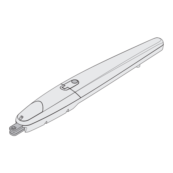
  • Page 26: Description Du Produit

    DESCRIPTION DU PRODUIT CARACTERISTIQUES TECHNIQUES Ce produit est à utiliser pour l’automation des grilles ou JETXL24 JETXL230 portails à vantaux battants de type résidentiel ou industriel. Max. leaf lenght ATTENTION! Toute autre utilisation que celle indiquée ou dans des Max. leaf weight conditions ambiantes différentes de celles signalées dans Power supply cette notice sera considérée comme inadéquate et de ce...
  • Page 27: Schéma D'installation

    SCHÉMA D’INSTALLATION COMPOSANTS AUTRES ACCESSOIRES Vérin Sélecteur à clé Armoire de commande Potelets avec photocellules Émetteur Barres palpeuses de sécurité Module récepteur Photocellules LONGUEUR DU CÂBLE < 10 mètres de 10 à 20 mètres de 20 à 30 mètres Alimentation 230V 3G x 1,5 mm 3G x 1,5 mm 3G x 2,5 mm...
  • Page 28: Mesures D'installation

    MESURES D’INSTALLATION Calculez la position de l’étrier arrière l’aide du graphique. Ce graphique permet d’établir les cotes A et E et la valeur de l’angle d’ouverture maximum du vantail. Important - Les valeurs A et E doivent être semblables entre elles pour permettre le mouvement linéaire de l’automatisation.
  • Page 29: Installation Du Motoréducteur Sur Les Étriers De Fixation

    INSTALLATION DU MOTORÉDUCTEUR Avant d’être fixé au mur, l’étrier doit être soudé sur sa plaque de fixation (Fig. 3); en cas de besoin l’étrier peut être coupé en SUR LES ÉTRIERS DE FIXATION adaptant en conséquence les valeurs des cotes A et E 1.
  • Page 30: Réglage Fin De Course

    4. Installez le motoréducteur sur l’étrier avant 2. Retirez les 2 vis placées sous la poignée et sortez le couvercle avant de la façon illustrée par la fig. 9. 5. Fixez le motoréducteur sur l’étrier de la façon illustrée par la fig.
  • Page 31 4. Amenez manuellement le vantail dans la position voulue à l’ouverture 5. Amenez ensuite la butée mécanique contre le pivot et vissez la vis (fig. 11) FIG.11 6. Répétez alors cette procédure en amenant manuellement le vantail dans la position de fermeture maximum, pour régler le fin de course à...
  • Page 32: Branchements Électrique

    BRANCHEMENTS ÉLECTRIQUE 3. Branchez les différents fils et le conducteur de la prise à la terre, exactement comme cela est indiqué sur le schéma électrique (fig. 15) ATTENTION! FIG.15 • Une erreur de branchement peut provoquer des pannes 230V et des situations dangereuses: veillez donc à respecter scrupuleusement les branchements indiqués.
  • Page 33: Advertencias Importantes

    ADVERTENCIAS IMPORTANTES • V2 declina cualquier responsabilidad por la inobservancia de las normas de construcción de buena técnica además de por las deformaciones estructurales de la cancela que podrían Es necesario leer todas las instrucciones antes de producirse durante su uso. proceder a la instalación ya que proporcionan indicaciones •...
  • Page 34: Verificaciones Preliminares E Identificación Del Tipo De Uso

    VERIFICACIONES PRELIMINARES E IDENTIFICACIÓN DEL TIPO DE USO Se recuerda que el automatismo no subviene a defectos causados por una errónea instalación, o por un mal mantenimiento, por tanto, antes de proceder a la instalación verifique que la estructura sea idónea y conforme con las normas vigentes y, si es el caso, aporte todas las modificaciones estructurales dirigidas a la realización de los flancos de seguridad y a la protección o aislamiento de todas las zonas de aplastamiento, cizallado, arrastre y verifique que: •...
  • Page 35: Límites De Uso

    DECLARACIÓN UE DE CONFORMIDAD La documentación técnica está a disposición de la autoridad competente bajo petición fundada en: Y DECLARACIÓN DE INCORPORACIÓN V2 S.p.A., Corso Principi di Piemonte 65, 12035, Racconigi (CN), Italia DE CUASI MÁQUINAS Declaración en conformidad con las Directivas: La persona autorizada para firmar la presente declaración de 2014/35/UE (LVD);...
  • Page 36: Descripción Del Producto

    DESCRIPCIÓN DEL PRODUCTO DATOS TÉCNICOS Este producto está destinado a ser utilizado para JETXL24 JETXL230 automatizar puertas o portones de hojas batientes, tanto para uso residencial como industrial. Longitud máx. hoja ATENCIÓN! Peso máx. hoja ¡Cualquier otro uso diferente del descrito y en condiciones Alimentacion ambientales diferentes de las indicadas en este manual debe considerarse impropio y prohibido!
  • Page 37: Diagrama De Instalación

    DIAGRAMA DE INSTALACIÓN COMPONENTES ACCESORIOS ADICIONALES Actuador Selector con llave Cuadro de maniobras Fotocélulas con columnas Emisor Bandas de seguridad Módulo receptor Fotocélulas Lámpara de señalización LONGITUD DEL CABLE < 10 metros de 10 a 20 metros de 20 a 30 metros Alimentación 230V 3G x 1,5 mm 3G x 1,5 mm...
  • Page 38: Medidas De Instalacion

    MEDIDAS DE INSTALACION PCalcular la posición del soporte trasero utilizando el gráfico. Este gráfico sirve para determinar las cotas A y E y el valor del ángulo de apertura máxima de la hoja. Importante – Los valores de A y E deben ser similares entre sí para permitir un movimiento lineal del automatización.
  • Page 39 INSTALACIÓN DEL MOTORREDUCTOR 5. El soporte, antes de ser fijado a la pared, se debe soldar en la placa de fijación específica (Fig. 3); si fuera necesario el EN LOS SOPORTES DE FIJACIÓN soporte se puede cortar adecuando en consecuencia los valores de las cotas A y E.
  • Page 40 4. Instalar el motorreductor en el soporte delantero. 2. Quitar los 2 tornillos ubicados debajo de la manilla y separar la tapa delantera como se indica en la imagen de la fig. 9. 5. Fijar el motorreductor al soporte como se muestra en la fig. 7 utilizando el tornillo y la arandela incluidos.
  • Page 41 4. Llevar manualmente la hoja a la posición deseada en apertura. 5. Después, llevar el tope mecánico hasta el final de carrera del perno y bloquear el tornillo (fig. 11); FIG.11 6. Entonces, repetir este procedimiento llevando manualmente la hoja a la posición de cierre máximo, para ajustar el final de carrera en cierre (fig.
  • Page 42: Conexiones Eléctricas

    CONEXIONES ELÉCTRICAS 3. Conecte los diferentes hilos y el cable de la toma a tierra, exactamente como se muestra en el esquema eléctrico de la fig. 15 ¡ATENCIÓN! FIG.15 • Una conexión equivocada puede provocar averías 230V o situaciones de peligro; por lo tanto, respete escrupulosamente las conexiones indicadas.
  • Page 43: Wichtige Hinweise

    WICHTIGE HINWEISE • V2 lehnt bei Nichtbeachtung der nach den allgemein anerkannten Regeln der Technik bestehenden Konstruktionsnormen und bei eventuell während des Es ist notwendig, vor Beginn der Installation alle Gebrauchs auftretenden strukturellen Deformationen des Tors Hinweise zu lesen, da diese wichtige Angeben zu Sicherheit, jede Haftung ab.
  • Page 44 VORBEREITENDE PRÜFUNGEN UND IDENTIFIZIERUNG DER NUTZUNGSTYPOLOGIE Es wird darauf hingewiesen, dass der Automatismus bei falscher Installation oder unsachgemäßer Wartung beschädigt werden kann und dass vor der Installation sichergestellt werden muss, dass die Struktur geeignet und mit den geltenden Normen konform ist und dass, wenn notwendig, alle strukturellen Änderungen vorzunehmen sind, um Sicherheit und Schutz zu gewährleisten und um alle Zonen abzutrennen, in denen Quetsch-, Scherungs- oder Mitreißgefahr herrscht.
  • Page 45 EU-KONFORMITÄTSERKLÄRUNG Die technische Dokumentation steht den zuständigen Behörden auf begründete Anfrage zur Verfügung bei: V2 S.p.A., Corso UND EINBAUERKLÄRUNG FÜR Principi di Piemonte 65, 12035, Racconigi (CN), Italien UNVOLLSTÄNDIGE MASCHINEN Folgende Person ist autorisiert, die Inkorporationserklärung zu Übereinstimmungserklärung mit den Richtlinien: unterzeichnen und die technische Dokumentation zur Verfügung 2014/35/EU (NSR);...
  • Page 46: Technische Daten

    BESTIMMUNGSZWECK TECHNISCHE DATEN Das vorliegende Produkt ist dazu bestimmt, als JETXL24 JETXL230 Antriebsautomatik für Flügeltore sowohl für Wohn- als auch für industrielle Zwecke zu dienen. Max. Torflügelweite ACHTUNG! Max. Torgewicht Jede andere Verwendung als die beschriebene oder unter Versongung anderen. Um ge bungsbedingungen als die in diesem Handbuch angegebenen gilt als missbräuchliche Verwendung Stromaufnahme ohne und ist verboten!
  • Page 47 INSTALLATIONSPLAN BAUTEILE ZUSATZZUBEHÖR Drehtorantrieb Schlüsselschalter Steuerung Fotozellen auf Säule Handsender Sicherheitskontaktleisten Empfangsmodul Fotozellen Blinklicht KABELLÄNGE < 10 Meter von 10 bis 20 Meter von 20 bis 30 Meter Spannungsversorgung 230V 3G x 1,5 mm 3G x 1,5 mm 3G x 2,5 mm Alimentação elétrica motore 230V 4G x 1,5 mm 4G x 1,5 mm...
  • Page 48 INSTALLATION Berechnen Sie die Position des hinteren Bügel mit Bezug auf Grafik. Diese Grafik dient zur Festlegung der Quoten A und E sowie des Winkels der max. Öffnung des Torflügels. Wichtig – Die Werte A und E müssen möglichst gleich sein, um eine lineare Bewegung der Automatisierung zu gestatten.
  • Page 49 INSTALLATION DES GETRIEBEMOTORS 5. Vor der Befestigung an der Mauer muss der Bügel an eine entsprechende Befestigungsplatte angeschweißt werden (Abb. AN DEN BEFESTIGUNGSBÜGELN 3); falls erforderlich kann der Bügel gemäß den Werten der Quoten A und E zugeschnitten werden 1. Installation des Getriebemotors auf dem hinteren Bügel: Abb.3 Anm.: Falls der hintere Bügel nicht vollkommen waagerecht ist, gestattet es das hintere Schwenkelement,...
  • Page 50 4. Installation des Getriebemotors auf dem vorderen Bügel. 2. Entfernen Sie die beiden Schrauben am Griff und ziehen Sie die vordere Abdeckung heraus, wie auf Abb. 9 gezeigt. 5. Befestigen Sie den Getriebemotor unter Verwendung der mitgelieferten Schraube und Scheibe am Bügel, wie gezeigt auf Abb.
  • Page 51 4. Bringen Sie den Torflügel von Hand in die gewünschte geöffnete Position. 5. Bringen Sie dann den Stoppermechanismus in Anschlag mit dem Bolzen und blockieren Sie die Schraube (Abb. 11). Abb.11 6. Wiederholen Sie an diesem Punkt dieses Verfahren und bringen Sie den Torflügel von Hand in die Position der maximalen Schließung, um den Anschlag Schließung einzustellen (Abb.
  • Page 52: Elektrische Anschlüsse

    ELEKTRISCHE ANSCHLÜSSE 3. Die verschiedenen Drähte und das Kabel der Erdleitung genau so anschließen, wie im Schaltbild von Abb. 15 gezeigt Abb.15 ACHTUNG! 230V • Ein falscher Anschluss kann Störungen oder Gefahrensituationen herbeiführen, daher sind die angegebenen Anschlüsse gewissenhaft zu befolgen. •...
  • Page 54: Technical Support

    +39 0172 1812574 Technical support More Monday/Friday 8.30-12.30 ; 14-18 (UTC+01:00 time) Dati dell’installatore / Installer details Azienda / Company Timbro / Stamp Località / Address Provincia / Province Recapito telefonico / Tel. Referente / Contact person Dati del costruttore / Manufacturer's details Brand of V2 S.p.A.

Table des Matières