Publicité

Les langues disponibles

Les langues disponibles

Liens rapides

A BRUCIATORI A GAS PROGRESSIVI E MODULANTI
B MODULATING AND PROGRESSIVE GAS BURNERS
C BRULEURS GAZ PROGRESSIVES ET MODULANTS
D QUEMADOR DE GAS PROGRESIVOS EN MODULANTE
G A S T E C
BLU 5000.1 PR / MD
BLU 6000.1 PR / MD
G20 - 70÷300 mbar
LB 832
28.04.2004

Publicité

Table des Matières
loading

Sommaire des Matières pour Ecoflam BLU 5000.1 PR

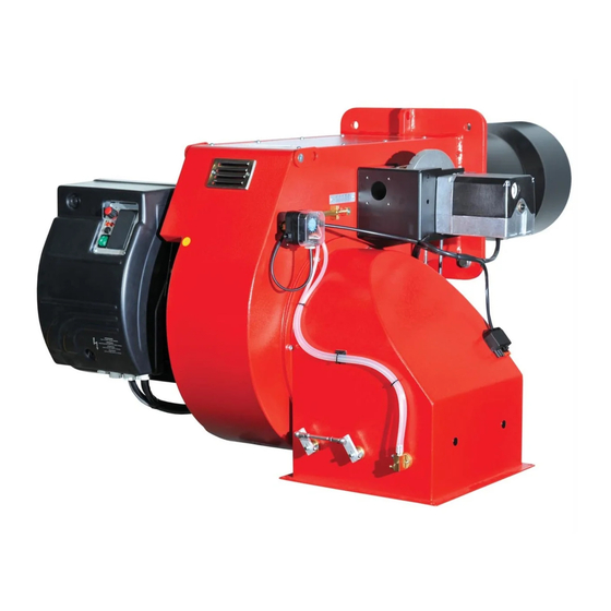
  • Page 1 B MODULATING AND PROGRESSIVE GAS BURNERS C BRULEURS GAZ PROGRESSIVES ET MODULANTS D QUEMADOR DE GAS PROGRESIVOS EN MODULANTE G A S T E C BLU 5000.1 PR / MD BLU 6000.1 PR / MD G20 - 70÷300 mbar LB 832...
  • Page 2: Dimensioni Di Ingombro

    A LB 832 BLU 5000.1 - 6000.1 PR / MD Caratteristiche tecniche bruciatori Blu 5000.1 PR Blu 6000.1 PR Blu 5000.1 MD Blu 6000.1 MD Potenza termica max. 5.000 5.800 5.000 5800 kcal/h 4.310.000 5.000.000 4.310.000 5.000.000 Potenza termica min.
  • Page 3: Allacciamento Elettrico

    A tal proposito vedere la tabella e la figura sottostanti. TALE OPERAZIONE DEVE ESSERE ESEGUITA DA PERSONALE PROFESSIONALMENTE QUALIFICATO ED AUTORIZZATO DALLA ECOFLAM SPA . NB-TUTTI GLI ORGANI DI SICUREZZA (PRESSOSTATO ARIA, PRESSOSTATO GAS DI MINIMA, ELETTRO-...
  • Page 4 A LB 832 BLU 5000.1 - 6000.1 PR / MD CICLO DI FUNZIONAMENTO DELL’APPARECCHIATURA LANDIS & STAEFA MOD. LFL1.622 Ciclo di funzionamento Ciclo di funzionamento normale in mancanza di fiamma all'accensione Pressostato gas Motore ventilatore Pressostato aria Trasformatore di accensione Valvola gas Rif.
  • Page 5 LB 832 BLU 5000.1 - 6000.1 PR / MD REGOLAZIONE DELLA PORTATA ARIA E GAS Part. 1 Part. 3 COMMUTATORE AUTO Part. 2 0 = bloccaggio degli apparati per il funzionamento in una posizione intermadia = funzionamento alla massima potenza = funzionamento alla minima potenza AUTO = funzionamento automatico REGOLAZIONE DELLA POTENZA MINIMA DEL GAS...
  • Page 6: Regolazione Della Combustione

    Le operazioni di rgolazione debbono essere effet- tuate da personale qualificato ed autorizzato dalla Ecoflam S.p.A. REGOLAZIONE TESTA DI COMBUSTIONE...
  • Page 7 LB 832 BLU 5000.1 - 6000.1 PR / MD CONTROLLO SISTEMA DI RILEVAZIONE FIAMMA Il controllo della corrente di ionizzazione si effettua inse- min. 6 µA rendo un microamperometro con fondo scala di 50 µA (corrente continua) in serie all'elettrodo di rivelazione. Un errato posizionamento dell'elettrodo può...
  • Page 8 A LB 832 BLU 5000.1 - 6000.1 PR / MD REGOLATORE A MICROPROCESSORE RWF 40 Significato del display e dei tasti del regolatore a microprocessore RWF 40 Nella figura viene visualizzato il display di base, Display: che indica il valore reale ed il setpoint ingresso analogico impostato, é...
  • Page 9: Funzionamento Manuale / Automatico

    LB 832 BLU 5000.1 - 6000.1 PR / MD IMPOSTAZIONI PARAMETRI All’accensione del bruciatore tutti i dislay del regolatore sono accesi, il display del setpoint lampeggerà per circa 10 sec. Il valore visualizzato nel dislay superiore (rosso) indica il valore reale. Il valore visualizzato nel dislay inferiore (verde) indica il valore del set- point impostato.
  • Page 10 A LB 832 BLU 5000.1 - 6000.1 PR / MD PARAMETRIZZAZIONE 17.5 12.5 -2.5 -7.5 -12.5 -17.5 Temperatura esterna (¡C) SCHEMI COLLEGAMENTO SONDE Collegamento sonda Cod. S721 Cod. RWF 40 Cod. QAE2..(sonda passiva) S720/1 S731 Sonda acqua S731/1 Codice configurazione S731/2 C111 = 9XXX 1 2 3 4...
  • Page 11 LB 832 BLU 5000.1 - 6000.1 PR / MD INDICAZIONI CONFIGURAZIONE INGRESSI C111 - C112 Ingresso analogico 1 (valore reale) Ingresso analogico 3 (temperatura esterna) Pt1000, 2 fili, Landis & Staefa IEC 751 Nessuna funzione (sonda non attiva) FT-TP/...(sonda passiva) Sonda esterna Pt 1000, 2 fili, Ni1000, 2 fili, Landis &...
  • Page 12 A LB 832 BLU 5000.1 - 6000.1 PR / MD NEL CASO DI NECESSITÀ DI SOSTITUZIONE PROCEDERE COME INDICATO NELLE SOTTOSTANTI FIGURE A-B-C Inserire il regolatore RWF 40 nell’apposita apertura del cassetto elettrico (A). Inserire nelle fessure i tasselli ad incastro con le viti, quindi bloccarla al pannello della cassetta per una corretta tenuta (B).
  • Page 13 LB 832 BLU 5000.1 - 6000.1 PR / MD IMPOSTAZIONI PARAMETRI Parametro Display Valore impostato Valore impostato Valore impostato (sonda passiva) (sonda passiva) (sonda attiva) QAE22 FT-TP/1000 QBE620-P... Valore limite del contatto ausiliario Differenziale di commutazione del contatto ausiliario HYSt Banda proporzionale Pb.1 Tempo dell’azione derivata...
  • Page 14: Working Fields

    B LB 832 BLU 5000.1 - 6000.1 PR / MD Technical data Blu 5000.1 PR Blu 6000.1 PR Blu 5000.1 MD Blu 6000.1 MD Thermal power max. 5.000 5.800 5.000 5.800 kcal/h 4.310.000 5.000.000 4.310.000 5.000.000 Thermal power min. 1.200 1.500...
  • Page 15: Electrical Connections

    LB 832 BLU 5000.1 - 6000.1 PR / MD B CONNECTION TO THE GAS PIPELINE Once connected the burner to the gas pipeline, it is necessary to control that this last is perfectly sealed. Also verify that the chimney is not obstructed. Open the gas cock and carefully bleed the piping through the pressure gauge connector, then check the pressure value trough a suitable gauge.
  • Page 16 B LB 832 BLU 5000.1 - 6000.1 PR / MD LANDIS & STAEFA, Model LFL1.622 OPERATING CYCLE Ref. Description Duration Operating cycle in the event of Ciclo di funzionamento Duration Waiting time for confirmation Normal operating cycle Ciclo di funzionamento normale ignition failureNormal operating cycle in mancanza di fiamma all'accensione of air pressure...
  • Page 17 LB 832 BLU 5000.1 - 6000.1 PR / MD B AIR ADJUSTMENT Part. 1 Part. 3 SELECTOR COMMUTATORE AUTO Part. 2 operating elements locked in an intermediate 0 = bloccaggio degli apparati per il position funzionamento in una posizione intermadia operation on maximum capacity = funzionamento alla massima potenza operation on minimum capacity...
  • Page 18: Combustion Adjustment

    The adjustments must be carried out by qualified and skilled techni- cians authorised by Ecoflam S.p.A. FIRING HEAD SETTING...
  • Page 19 LB 832 BLU 5000.1 - 6000.1 PR / MD B IONIZATION CURRENT The ionization current is checked by inserting a microam- meter with an end of scale of 50 µA (d.c.) in series with the min. 6 µA ionization probe. A faulty position of the electrode can lead to a reduction in the ionization current and cause a safety cut-out of the burner due to a flame detection failure.
  • Page 20 B LB 832 BLU 5000.1 - 6000.1 PR / MD RWF 40 MICROPROCESSOR REGULATOR Description of display and keys on the RWF 40 microprocessor regulator The figure shows the normal display indicating Display: the actual value and the programmed set analog input 1 point, and equally important, (actual value)
  • Page 21: Manual/Automatic Mode

    LB 832 BLU 5000.1 - 6000.1 PR / MD B SETTING PARAMETERS When the burner is ignited all displays of the regulator light up. The set point display will blink for about 10 seconds. The value in the upper field of the display (red) indicates the actual value. The value in the lower field of the display (green) indicates the set point currently programmed.
  • Page 22 B LB 832 BLU 5000.1 - 6000.1 PR / MD PARAMETERIZATION 12.5 -2.5 -7.5 -12.5 -17.5 17.5 External temperature (iC) PROBE CONNECTION DIAGRAMS Connection for probe Cod. S721 Cod. RWF 40 Cod. QAE2..(passive probe) S720/1 S731 Water probe S731/1 Configuration code S731/2 C111 = 9XXX 1 2 3 4...
  • Page 23 LB 832 BLU 5000.1 - 6000.1 PR / MD B C111 – C112 INPUT CONFIGURATION INDICATIONS Analog input 1 (actual value) Analog Input 3 (external temperature) Pt1000, 2-wire, Landis & Staefa IEC 751 No function (probe not active) FT-TP/… (passive probe) External probe Pt 1000, 2-wire, QAC22 (passive probe) Ni1000, 2-wire, Landis &...
  • Page 24 B LB 832 BLU 5000.1 - 6000.1 PR / MD WHEN REPLACEMENT IS NECESSARY, PROCEED AS SHOWN IN FIGURES A-B-C BELOW Insert the RWF 40 regulator through the relative opening in the electrical panel (A). Insert the fixing anchors and screws into the slots, and secure the unit to the panel (B). To open the regulator, squeeze the cover from the ends as shown, and lift out (C).
  • Page 25: Configuration

    LB 832 BLU 5000.1 - 6000.1 PR / MD B PARAMETERS Parameter Display Ecoflam setting Ecoflam setting Ecoflam setting (passive probe) (passive probe) (active probe) QAE22 FT-TP/1000 QBE620-P... Limit value of limit comparator Switching differential for limit comparator HYSt Proportional band Pb.1...
  • Page 26: Courbe De Travail

    C LB 832 BLU 5000.1 - 6000.1 PR / MD Caracteristiques du bruleur Blu 5000.1 PR Blu 6000.1 PR Blu 5000.1 MD Blu 6000.1 MD Puissance termique max. 5.000 5.800 5.000 5.800 kcal/h 4.310.000 4.310.000 5.000.000 5.000.000 Puissance termique min.
  • Page 27: Connexion Electrique

    à ce que les valeurs relevées soient correctes, et qu’elles répondent toujours aux normes de sécurité en vigueur. CETTE OPÉRATION DOIT ETRE FAITE PAR DU LA PERSONNEL QUALIFIÉ ET AUTORISÉ PAR LA SOCIÉTÉ ECOFLAM SPA . Gaz Nat. 1,25 9,6% CO <100 ppm...
  • Page 28: Servomoteur Landis & Staefa Sqm 50.481A2

    C LB 832 BLU 5000.1 - 6000.1 PR / MD COFFRETS DE SECURITE LANDIS & STAEFA MOD. LFL1.622 Cycle de fonctionnement par manque Ref. Description Ciclo di funzionamento Temps Cycle de fonctionnement normal Temps de contrôle du pressostat air Ciclo di funzionamento normale in mancanza di fiamma all'accensione de flamme d'allumage 8”...
  • Page 29 LB 832 BLU 5000.1 - 6000.1 PR / MD REGLAGES DES DEBITS AIR ET GAZ Part. 1 Part. 3 COMMUTATEUR COMMUTATORE AUTO Part. 2 blocage du servomoteur dans une position 0 = bloccaggio degli apparati per il intermédiaire funzionamento in una posizione intermadia = funzionamento alla massima potenza fonctionnement à...
  • Page 30: Regulation De La Combustion

    à une analyse de la combustion, à se faire par des instruments opportuns, en vérifiant que les données sont correctes et correspondantes aux normes de sécurité locales. Les opérations de régulations doivent être effectuées par des techniciens experts et qualifiés, autorisés par Ecoflam S.p.A. REGULATION DE LA TETE DE COMBUSTION POSITION DES ELECTRODES Electrode d’allumage...
  • Page 31: Controle Systeme Detection De Flamme

    LB 832 BLU 5000.1 - 6000.1 PR / MD CONTROLE SYSTEME DETECTION DE FLAMME Avec le brûleur énteint, brancher un microampe- min. 6 µA romètre à courante continue scale 50 µA. Si posi- tionè erronéament, l’électrode peut provoquer l’arrêt du brûleur. Il faut bien contrôler la position de l’electrode, les branchements eletriques et la mise LANDIS LFL1.622 à...
  • Page 32 C LB 832 BLU 5000.1 - 6000.1 PR / MD REGULATEUR COMPACT UNIVERSEL RWF40 Déscription de l’affichage à cristaux liquides (display) et des touches du regulateur RWF40 Affichage à cristaux liquides: Entrée analogique 1 (valeur réelle) Affichage à cristaux liquides: consigne SP1 Signal commande manuelle...
  • Page 33: Introduction Des Parametres

    LB 832 BLU 5000.1 - 6000.1 PR / MD INTRODUCTION DES PARAMETRES A l’allumage du brûleur tous les LED sur la façade sont allumés. L’ affichage à cristaux liquides (display) du consigne clignotera pour environ 10sec. L’affichage à cristaux liquides supérieur (rouge) indique la valeur mesurée et pendant le reglage, il indique les paramètres entrés;...
  • Page 34 C LB 832 BLU 5000.1 - 6000.1 PR / MD PARAMETRISATION 17.5 12.5 -2.5 -7.5 -12.5 -17.5 température éxtérieure (°C) Schéma de branchement avec les sondes Branchement sonde Cod. S721 Cod. RWF 40 Cod. QAE2..(sonde passive) S720/1 S731 Sonde eau S731/1 Code C111 = 9XXX S731/2...
  • Page 35: Signalation Des Fautes Et D' Anomalies Clignotement Du Numero Sur L'affichage A' Cristaux Liquides (Display)

    LB 832 BLU 5000.1 - 6000.1 PR / MD INDICATION DE CONFIGURATION ENTREES C111-C112 Entrée analogique 1 (valeur réelle) Entrée analogique 3 (température éxtérieure) Pt1000, 2 fils, Landis & Staefa IEC 751 Aucune fonction (sonde non active) FT-TP/...(sonde passive ) Sonde éxtérieure Pt 1000, 2 fils, Ni1000, 2 fils, Landis &...
  • Page 36: Controle Annuel

    C LB 832 BLU 5000.1 - 6000.1 PR / MD SUBSTITUTION DU REGULATEUR Les déscriptions A,B,C indiquent comme l’on doit démonter et remonter le régulateur RWF40. C – Pour enlever le régulateur, exercer une pression sur le couvercle et enléver le même. A –...
  • Page 37 LB 832 BLU 5000.1 - 6000.1 PR / MD IMPOSTAZIONI PARAMETRI Parametro Display Valore impostato Valore impostato Valore impostato (sonda passiva) (sonda passiva) (sonda attiva) QAE22 FT-TP/1000 QBE620-P... Valore limite del contatto ausiliario Differenziale di commutazione del contatto ausiliario HYSt Banda proporzionale Pb.1 Tempo dell’azione derivata...
  • Page 38: Campo De Trabajo

    D LB 832 BLU 5000.1 - 6000.1 PR / MD Caracteristicas tecnicas Blu 5000.1 PR Blu 6000.1 PR Blu 5000.1 MD Blu 6000.1 MD Potencia térmica máx. 5.000 5.800 5.000 5.800 kcal/h 4.310.000 5.000.000 4.300.000 5.000.000 Potencia térmica min. 1.200 1.500...
  • Page 39: Conexión A La Red

    ESTA OPERACION TIENE QUE SER EFECTUADA POR TÉCNICOS PROFESIONALMENTE CALIFICA- DOS Y AUTORIZADOS POR ECOFLAM S.P.A. Gas Nat. 1,25 9,6% CO <100 ppm...
  • Page 40 D LB 832 BLU 5000.1 - 6000.1 PR / MD CICLOS DE FUNCIONAMIENTO DEL EQUIPO LANDIS & STAEFA MOD. LFL1.622 Ciclo de funcionamiento con falta Ref. Descripción Duración Ciclo di funzionamento Ciclo de funcionamiento normal Tiempo de espera de la confirmación Ciclo di funzionamento normale in mancanza di fiamma all'accensione de llama al arranque...
  • Page 41 LB 832 BLU 5000.1 - 6000.1 PR / MD REGULACIÓN DEL CAUDAL DE AIRE Y GAS Part. 1 Part. 3 CONMUTADOR COMMUTATORE AUTO Part. 2 0 = bloccaggio degli apparati per il Bloqueo de los equipos para funzionamento in una posizione intermadia funcionamiento en una posición intermedia = funzionamento alla massima potenza Funcionamiento a la potencia máxima...
  • Page 42: Regulacion Cabeza De Combustion

    Las operaciones de regulación tienen que ser efectuadas por técnicos expertos y calificados, autorizados por Ecoflam S.p.A. REGULACION CABEZA DE COMBUSTION POSICIÓN DE LOS ELECTRODOS...
  • Page 43: Corriente De Ionización

    LB 832 BLU 5000.1 - 6000.1 PR / MD CORRIENTE DE IONIZACIÓN El controle de la corriente de ionización se efectúa min. 6 µA conectando un microamperímetro de escala de 50 µA (corriente continua)en serie al electrodo de ioni- zación. Una colocación errada del electrodo puede comportar una reducción de la corriente de ioniza- LANDIS LFL1.622 ción y causar un bloqueo en seguridad del quema-...
  • Page 44 D LB 832 BLU 5000.1 - 6000.1 PR / MD CONTROLADOR MICROPROCESADOR RWF 40 Significado del display y de los botones del controlador microprocesador RWF 40 La pantalla del RWF40... muestra los valores y símbolos de una situación tras ser conectado. Esta situación es la del display Display valor real básico.
  • Page 45 LB 832 BLU 5000.1 - 6000.1 PR / MD MANEJO DE LOS PARAMETROS En el encendido del quemador todos los displays están iluminados, el display de la consigna parpadea durante unos 10segundos tras su conexión. El valor real aparece en el display de valor real (rojo). La consigna aparece en el display de consigna (verde). CAMBIO CONSIGNA Para modificar las consignas hay que proceder como sigue: - - Con el tras...
  • Page 46: Esquema De Conexion Sonda

    D LB 832 BLU 5000.1 - 6000.1 PR / MD Parametrización 17.5 12.5 -2.5 -7.5 -12.5 -17.5 Temperatura exterior (°C) ESQUEMA DE CONEXION SONDA Conexión sonda Cod. S721 Cod. RWF 40 Cod. QAE2..(sonda pasiva) S720/1 S731 Sonda agua S731/1 Código de configuración S731/2 C111 = 9XXX 1 2 3 4...
  • Page 47 LB 832 BLU 5000.1 - 6000.1 PR / MD CONFIGURACION ENTRADAS C111 - C112 Entrada analógica 1 (valor real) Entrada analógica 3 (temperatura exterior) Pt1000, 2 hilos, Landis & Staefa IEC 751 Ninguna función (sonda no activa) FT-TP/...(sonda pasiva) Sonda exterior Pt 1000, 2 hilos, Ni1000, 2 hilos, Landis &...
  • Page 48: Control Anual

    D LB 832 BLU 5000.1 - 6000.1 PR / MD EN CASO DE NECESIDAD DI SUSTITUCIÓN PROCEDER COMO ESTA INDICADO EN LAS FIGURAS SUBRAYADAS A-B-C Insertar frontalmente el controlador en el cuadro. (A). En la parte posterior del cuadro, acoplar los elementos de fijación en las ranuras laterales o superiores.
  • Page 49 LB 832 BLU 5000.1 - 6000.1 PR / MD IMPOSICION DE PARAMETROS Parametro Display Valor impuesto Valor impuesto Valor impuesto (sonda pasiva) (sonda pasiva) (sonda activa) QAE22 FT-TP/1000 QBE620-P... Valor limite del contacto auxiliar Diferencial de conmutación del contacto auxiliar HYSt Banda proporcional Pb.1...
  • Page 50 ABCD LB 832 BLU 5000.1 - 6000.1 PR / MD pag.50...
  • Page 51 LB 832 BLU 5000.1 - 6000.1 PR / MD N° DESCRIZIONE BLU 5000.1PR BLU 6000.1 PR codice codice 1 - PRESSOSTATO ARIA DUNGS LGW10 A2P Q120 Q120 2 - GRUPPO PRESE ARIA GRPA100 GRPA100 3 - SPINA WIELAND 6 poli E226 E226 4 - COPERCHIO...
  • Page 52 B LB 832 BLU 5000.1 - 6000.1 PR / MD Modulair P 5000.1 Modulair P 6000.1 N° DESCRIPTION BLU PR 5000.1 BLU PR 6000.1 code code 1 - AIR PRESSURE SWITCH DUNGS LGW10 A2P Q120 Q120 2 - AIR INTAKE SET GRPA100 GRPA100 3 - PLUG WIELAND...
  • Page 53 LB 832 BLU 5000.1 - 6000.1 PR / MD N° DESIGNATION BLU 5000.1 PR BLU 6000.1 PR code code 1 - PRESSOSTAT AIR DUNGS LGW10 A2P Q120 Q120 2 - SET DE PRISES D’AIR GRPA100 GRPA100 3 - FICHE FEMELE WIELAND...
  • Page 54 D LB 832 BLU 5000.1 - 6000.1 PR / MD N° DESCRIPCION BLU 5000.1 PR BLU 6000.1 PR código código 1 - PRESÓSTATO AIRE DUNGS LGW10 A2P Q120 Q120 2 - COJUNTO TOMAS DE AIRE GRPA100 GRPA100 3 - ESPIA WIELAND...
  • Page 55 ABCD LB 832 BLU 5000.1 - 6000.1 PR / MD pag.55...
  • Page 56 ABCD LB 832 BLU 5000.1 - 6000.1 PR / MD pag.56...
  • Page 57 ABCD LB 832 BLU 5000.1 - 6000.1 PR / MD pag.57...
  • Page 58 ABCD LB 832 BLU 5000.1 - 6000.1 PR / MD pag.58...
  • Page 59 ABCD LB 832 BLU 5000.1 - 6000.1 PR / MD pag.59...
  • Page 60 Ecoflam S.p.A. via Roma, 64 - 31023 RESANA (TV) - Italy - tel. 0423/715345 r.a. telefax 0423-715444 (Italy 480009 - Export 480873, 715538). http://www.ecoflam.it - e-mail: ecoflam@ecoflam.it...

Ce manuel est également adapté pour:

Blu 5000.1 mdBlu 6000.1 prBlu 6000.1 md

Table des Matières