Table des Matières
Publicité
Les langues disponibles
Les langues disponibles
Liens rapides
Version 1.0
Published January 2017
Copyright©2017 ASRock INC. All rights reserved.
Copyright Notice:
No part of this documentation may be reproduced, transcribed, transmitted, or
translated in any language, in any form or by any means, except duplication of
documentation by the purchaser for backup purpose, without written consent of
ASRock Inc.
Products and corporate names appearing in this documentation may or may not
be registered trademarks or copyrights of their respective companies, and are used
only for identification or explanation and to the owners' benefit, without intent to
infringe.
Disclaimer:
Specifications and information contained in this documentation are furnished for
informational use only and subject to change without notice, and should not be
constructed as a commitment by ASRock. ASRock assumes no responsibility for
any errors or omissions that may appear in this documentation.
With respect to the contents of this documentation, ASRock does not provide
warranty of any kind, either expressed or implied, including but not limited to
the implied warranties or conditions of merchantability or fitness for a particular
purpose.
In no event shall ASRock, its directors, officers, employees, or agents be liable for
any indirect, special, incidental, or consequential damages (including damages for
loss of profits, loss of business, loss of data, interruption of business and the like),
even if ASRock has been advised of the possibility of such damages arising from any
defect or error in the documentation or product.
This device complies with Part 15 of the FCC Rules. Operation is subject to the following
two conditions:
(1) this device may not cause harmful interference, and
(2) this device must accept any interference received, including interference that
may cause undesired operation.
CALIFORNIA, USA ONLY
The Lithium battery adopted on this motherboard contains Perchlorate, a toxic substance
controlled in Perchlorate Best Management Practices (BMP) regulations passed by the
California Legislature. When you discard the Lithium battery in California, USA, please
follow the related regulations in advance.
"Perchlorate Material-special handling may apply, see www.dtsc.ca.gov/hazardouswaste/
perchlorate"
ASRock Website: http://www.asrock.com
Publicité
Table des Matières

Manuels Connexes pour ASROCK Fatal1ty AB350


Sommaire des Matières pour ASROCK Fatal1ty AB350
- Page 1 (including damages for loss of profits, loss of business, loss of data, interruption of business and the like), even if ASRock has been advised of the possibility of such damages arising from any defect or error in the documentation or product.
- Page 2 If you require assistance please call ASRock Tel : +886-2-28965588 ext.123 (Standard International call charges apply) The terms HDMI™...
- Page 3 Fatal1ty Story Who knew that at age 19, I would be a World Champion PC gamer. When I was 13, I actually played competitive billiards in professional tournaments and won four or five games off guys who played at the highest level. I actually thought of making a career of it, but at that young age situations change rapidly.
- Page 4 LIVIN’ LARGE Since my first big tournament wins, I have been a “Professional Cyberathlete”, traveling the world and livin’ large with lots of International media coverage on outlets such as MTV, ESPN and a 60 Minutes segment on CBS to name only a few. It's unreal - it's crazy. I’m living a dream by playing video games for a living.
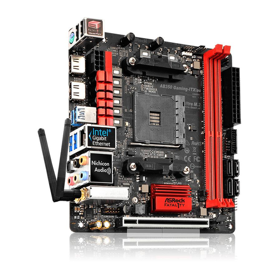
- Page 5 Fatal1ty AB350 Gaming K4 Series Motherboard Layout CPU_FAN1 ATX12V1 USB 3.0 T: USB31_TA_1 B: USB31_TC_1 USB 3.0 T: USB1 B: USB2 USB 3.0 T: USB3 B: USB4 Ultra M.2 PCIe Gen3 x4 CHA_FAN3 BIOS PCIE1 PCIE2 AB350 Gaming K4 CMOS...
- Page 6 No. Description ATX 12V Power Connector (ATX12V1) CPU Fan Connector (CPU_FAN1) 2 x 288-pin DDR4 DIMM Slots (DDR4_A1, DDR4_B1) 2 x 288-pin DDR4 DIMM Slots (DDR4_A2, DDR4_B2) AMD Fan LED Header (AMD_FAN_LED1) RGB LED Header (RGB_HEADER1) ATX Power Connector (ATXPWR1) USB 3.0 Header (USB3_5_6) SATA3 Connector (SATA3_2) SATA3 Connector (SATA3_1)
- Page 7 Fatal1ty AB350 Gaming K4 Series I/O Panel No. Description No. Description Fatal1ty Mouse Port (USB1) USB 3.0 Ports (USB3_34) USB 2.0 Port (USB2) USB 3.0 Ports (USB3_12) DVI-D Port USB 3.0 Port (USB31_TA_1) LAN RJ-45 Port* USB 3.0 Type-C Port (USB31_TC_1)
- Page 8 ** To configure 7.1 CH HD Audio, it is required to use an HD front panel audio module and enable the multi- channel audio feature through the audio driver. Please set Speaker Configuration to “7.1 Speaker”in the Realtek HD Audio Manager. Function of the Audio Ports in 7.1-channel Configuration: Port Function...
-
Page 9: Package Contents
If you require technical support related to this motherboard, please visit our website for specific information about the model you are using. You may find the latest VGA cards and CPU support list on ASRock’s website as well. ASRock website http://www.asrock.com. - Page 10 • AMD 7 Gen A-Series APUs support DDR4 2400/2133 ECC & non-ECC, un-buffered memory* * Please refer to Memory Support List on ASRock’s website for more information. (http://www.asrock.com/) * Please refer to page 22 for DDR4 UDIMM maximum frequency support.
- Page 11 Fatal1ty AB350 Gaming K4 Series • Integrated AMD Radeon Graphics R7/R5 Series Graphics in A-series • DirectX 12, Pixel Shader 5.0 • Max. shared memory 2GB • Three graphics output options: D-Sub, DVI-D and HDMI • Supports Triple Monitor • Supports HDMI with max. resolution up to 4K x 2K (4096x2160) @ 24Hz / (3840x2160) @ 30Hz • Supports DVI-D with max.
- Page 12 • 1 x M.2 Socket (M2_2), supports type 2230/2242/2260/2280/22110 M.2 SATA3 6.0 Gb/s module ** If M2_1 is occupied, PCIE4 will be disabled. ** Supports NVMe SSD as boot disks ** Supports ASRock U.2 Kit • 1 x COM Port Header Connector • 1 x TPM Header • 1 x Power LED and Speaker Header...
- Page 13 • CPU/Chassis Quiet Fan • CPU/Chassis Fan multi-speed control • Voltage monitoring: +12V, +5V, +3.3V, Vcore • Microsoft® Windows® 10 64-bit * For the updated Windows® 10 driver, please visit ASRock’s web- site for details: http://www.asrock.com • FCC, CE, WHQL Certifica- • ErP/EuP ready (ErP/EuP ready power supply is required)
- Page 14 Chapter 2 Installation This is an ATX form factor motherboard. Before you install the motherboard, study the configuration of your chassis to ensure that the motherboard fits into it. Pre-installation Precautions Take note of the following precautions before you install motherboard components or change any motherboard settings.
- Page 15 Fatal1ty AB350 Gaming K4 Series 2.1 Installing the CPU Unplug all power cables before installing the CPU.
- Page 16 English...
- Page 17 Fatal1ty AB350 Gaming K4 Series 2.2 Installing the CPU Fan and Heatsink After you install the CPU into this motherboard, it is necessary to install a larger heatsink and cooling fan to dissipate heat. You also need to spray thermal grease between the CPU and the heatsink to improve heat dissipation.
- Page 19 Fatal1ty AB350 Gaming K4 Series Installing the AM4 Box Cooler SR2...
- Page 20 English...
- Page 21 Fatal1ty AB350 Gaming K4 Series 4-pin FAN cable RGB LED Cable +12V *The diagram shown here are for reference only. Please refer to page 30 for the orientation of AMD Fan LED Header (AMD_FAN_LED1).
- Page 22 Installing the AM4 Box Cooler SR3...
- Page 23 Fatal1ty AB350 Gaming K4 Series...
- Page 25 +12V Please note that only one cable should be used at a time in this step. If you select AMD_FAN_LED1, please install ASRock utility "ASRock RGB LED". If you select USB connector, please install AMD utility "SR3 Settings Software". *The diagram shown here are for reference only. Please refer to page 30 for the orientation of AMD Fan...
- Page 26 2.3 Installing Memory Modules (DIMM) This motherboard provides four 288-pin DDR4 (Double Data Rate 4) DIMM slots, and supports Dual Channel Memory Technology. 1. For dual channel configuration, you always need to install identical (the same brand, speed, size and chip-type) DDR4 DIMM pairs. 2.
- Page 27 Fatal1ty AB350 Gaming K4 Series The DIMM only fits in one correct orientation. It will cause permanent damage to the motherboard and the DIMM if you force the DIMM into the slot at incorrect orientation.
- Page 28 2.4 Expansion Slots (PCI Express Slots) There are 6 PCI Express slots on the motherboard. Before installing an expansion card, please make sure that the power supply is switched off or the power cord is unplugged. Please read the documentation of the expansion card and make necessary hardware settings for the card before you start the installation.
- Page 29 Fatal1ty AB350 Gaming K4 Series 2.5 Jumpers Setup The illustration shows how jumpers are setup. When the jumper cap is placed on the pins, the jumper is “Short”. If no jumper cap is placed on the pins, the jumper is “Open”. The illustration shows a 3-pin jumper whose pin1 and pin2 are “Short”...
- Page 30 2.6 Onboard Headers and Connectors Onboard headers and connectors are NOT jumpers. Do NOT place jumper caps over these headers and connectors. Placing jumper caps over the headers and connectors will cause permanent damage to the motherboard. System Panel Header Connect the power PLED+ PLED-...
- Page 31 Fatal1ty AB350 Gaming K4 Series Power LED and Speaker Please connect the SPEAKER DUMMY Header chassis power LED and DUMMY (7-pin SPK_PLED1) the chassis speaker to this (see p.1, No. 15) header. PLED+ PLED+ PLED- Serial ATA3 Connectors These six SATA3...
- Page 32 Front Panel Audio Header This header is for PRESENCE# MIC_RET (9-pin HD_AUDIO1) connecting audio devices OUT_RET (see p.1, No. 24) to the front audio panel. OUT2_L J_SENSE OUT2_R MIC2_R MIC2_L 1. High Definition Audio supports Jack Sensing, but the panel wire on the chassis must support HDA to function correctly.
- Page 33 Fatal1ty AB350 Gaming K4 Series ATX Power Connector This motherboard pro- (24-pin ATXPWR1) vides a 24-pin ATX power (see p.1, No. 7) connector. To use a 20-pin ATX power supply, please plug it along Pin 1 and Pin ATX 12V Power...
- Page 34 RGB LED Header RGB LED header is used to con- (4-pin RGB_HEADER1) nect RGB LED extension cable (see p.1, No. 6) which allows users to choose from various LED lighting ef- fects. Caution: Never install the RGB LED cable in the wrong orienta- tion;...
- Page 35 Fatal1ty AB350 Gaming K4 Series 2.7 M.2_SSD (NGFF) Module Installation Guide (M2_1) The M.2, also known as the Next Generation Form Factor (NGFF), is a small size and versatile card edge connector that aims to replace mPCIe and mSATA. The Ultra M.2 Socket (M2_1) supports type 2242/2260/2280 M.2 PCI Express module up to Gen3 x4 (32...
- Page 36 Step 3 Move the standoff based on the module type and length. The standoff is placed at the nut location C by default. Skip Step 3 and 4 and go straight to Step 5 if you are going to use the default nut. Otherwise, release the standoff by hand.
- Page 37 Fatal1ty AB350 Gaming K4 Series Step 6 Tighten the screw with a screwdriver to secure the module into place. Please do not overtighten the screw as this might damage the module. NUT2 NUT1 M.2_SSD (NGFF) Module Support List Vendor Interface...
- Page 38 2.8 M.2_SSD (NGFF) Module Installation Guide (M2_2) The M.2, also known as the Next Generation Form Factor (NGFF), is a small size and versatile card edge connector that aims to replace mPCIe and mSATA. The M.2 Socket (M2_2) supports type 2230/2242/2260/2280/22110 M.2 SATA3 6.0 Gb/s module. * M2_2 and SATA3_3 share lanes.
- Page 39 Fatal1ty AB350 Gaming K4 Series Step 3 Move the standoff based on the module type and length. The standoff is placed at the nut location D by default. Skip Step 3 and 4 and go straight to Step 5 if you are going to use the default nut.
- Page 40 SATA Transcend TS256GMTS800-256GB Transcend SATA Transcend TS64GMTS400-64GB V-Color SATA V-Color 120G V-Color SATA V-Color 240G SATA WD BLUE WDS100T1B0B-00AS40 SATA WD GREEN WDS240G1G0B-00RC30 For the latest updates of M.2_SSD (NFGG) module support list, please visit our website for details: http://www.asrock.com...
-
Page 41: Lieferumfang
Inhalt dieser Anleitung ohne Ankündigung geändert werden. Falls diese Anleitung irgendwelchen Änderungen unterliegt, wird die aktualisierte Version ohne wei- tere Hinweise auf der ASRock-Webseite zur Verfügung gestellt. Sollten Sie technische Hilfe in Bezug auf dieses Motherboard benötigen, erhalten Sie auf unserer Webseite spezifischen Informationen über das von Ihnen verwendete Modell. -
Page 42: Technische Daten
• APUs von AMDs A-Serie der 7. Generation unterstützen un- gepufferten DDR4-2400/2133-ECC- und -Non-ECC-Speicher* * Weitere Informationen finden Sie in der Speicherkompatibilität- sliste auf der ASRock-Webseite. (http://www.asrock.com/) * Bitte beachten Sie Seite 22 für die maximal unterstützte Frequenz von DDR4-UDIMM. - Page 43 Fatal1ty AB350 Gaming K4 Series • Integrierte Grafikkarte der AMD-Radeon Grafikkarte -R7/R5-Serie in APU der A-Serie • DirectX 12, Pixel Shader 5.0 • Max. geteilter Speicher: 2GB • Drei Grafikkarten-Ausgangsoptionen: D-Sub, DVI-D und HDMI • Unterstützt drei Monitore • Unterstützt HDMI mit maximaler Auflösung von 4K x 2K (4096 x 2160) bei 24 Hz / (3840 x 2160) bei 30 Hz • Unterstützt DVI-D mit maximaler Auflösung von 1920 x 1200...
- Page 44 Gen3 x2 (16 Gb/s) (mit APU der A-Serie)** • 1 x M.2-Sockel (M2_2), unterstützt 2230/2242/2260/2280/22110-M.2-SATA-III-6,0-Gb/s-Modul ** Wenn M2_1 belegt ist, wird PCIE4 deaktiviert. ** Unterstützt NVMe-SSD als Bootplatte ** Unterstützt ASRock U.2-Kit • 1 x COM-Anschluss-Stiftleiste Anschluss • 1 x TPM-Stiftleiste • 1 x Betrieb-LED- und Lautsprecher-Stiftleiste • 1 x RGB-LED-Stiftleiste...
- Page 45 Zertifizierun- • ErP/EuP ready (ErP/EuP ready-Netzteil erforderlich) * Detaillierte Produktinformationen finden Sie auf unserer Webseite: http://www.asrock.com Bitte beachten Sie, dass mit einer Übertaktung, zu der die Anpassung von BIOS-Einstel- lungen, die Anwendung der Untied Overclocking Technology oder die Nutzung von Über- taktungswerkzeugen von Drittanbietern zählen, bestimmte Risiken verbunden sind.
- Page 46 1.3 Jumpereinstellung Die Abbildung zeigt, wie die Jumper eingestellt werden. Wenn die Jumper-Kappe auf den Kontakten angebracht ist, ist der Jumper „kurzgeschlossen“. Wenn keine Jumper- Kappe auf den Kontakten angebracht ist, ist der Jumper „offen“. Die Abbildung zeigt einen 3-poligen Jumper, dessen Kontakt 1 und Kontakt 2 „kurzgeschlossen“ sind, wenn eine Jumper-Kappe auf diesen 2 Kontakten angebracht ist.
- Page 47 Fatal1ty AB350 Gaming K4 Series 1.4 Integrierte Stiftleisten und Anschlüsse Integrierte Stiftleisten und Anschlüsse sind KEINE Jumper. Bringen Sie KEINE Jumper- Kappen an diesen Stiftleisten und Anschlüssen an. Durch Anbringen von Jumper-Kappen an diesen Stiftleisten und Anschlüssen können Sie das Motherboard dauerhaft beschädigen.
- Page 48 Betrieb-LED- und Bitte verbinden Sie SPEAKER DUMMY Lautsprecher-Stiftleiste die Betrieb-LED des DUMMY (7-polig, SPK_PLED1) Gehäuses und den (siehe S. 1, Nr. 15) Gehäuselautsprecher mit dieser Stiftleiste. PLED+ PLED+ PLED- Serial-ATA-III-Anschlüsse Diese sechs SATA-III- (SATA3_1: Anschlüsse unterstützen siehe S. 1, Nr. 10) SATA-Datenkabel für (SATA3_2: interne Speichergeräte mit...
- Page 49 Fatal1ty AB350 Gaming K4 Series Audiostiftleiste Diese Stiftleiste dient PRESENCE# MIC_RET (Frontblende) dem Anschließen von OUT_RET (9-polig, HD_AUDIO1) Audiogeräten an der (siehe S. 1, Nr. 24) Frontblende. OUT2_L J_SENSE OUT2_R MIC2_R MIC2_L 1. High Definition Audio unterstützt Anschlusserkennung, der Draht am Gehäuse muss dazu jedoch HDA unterstützt.
- Page 50 ATX-Netzanschluss Dieses Motherboard bietet (24-polig, ATXPWR1) einen 24-poligen ATX-Net- (siehe S. 1, Nr. 7) zanschluss. Bitte schließen Sie es zur Nutzung eines 20-po- ligen ATX-Netzteils entlang Kontakt 1 und Kontakt 13 an. ATX-12-V-Netzanschluss Dieses Motherboard bietet (8-polig, ATX12V1) einen 8-poligen ATX-12-V- (siehe S.
- Page 51 Fatal1ty AB350 Gaming K4 Series RGB-LED-Stiftleiste RGB-LED-Stiftleiste dient (4-polig, RGB_HEAD- dem Anschließen eines RGB- ER1) LED-Erweiterungskabels, (siehe S. 1, Nr. 6) das dem Nutzer die Auswahl zwischen verschiedenen LED- Lichteffekten ermöglicht. Achtung: Installieren Sie das RGB-LED-Kabel niemals falsch herum; andernfalls könnte das Kabel beschädigt...
-
Page 52: Contenu De L'emballage
à modification sans préavis. En cas de modifications du présent document, la version mise à jour sera disponible sur le site Internet ASRock sans notifica- tion préalable. Si vous avez besoin d’une assistance technique pour votre carte mère, veuillez visiter notre site Internet pour plus de détails sur le modèle que vous utilisez. - Page 53 Fatal1ty AB350 Gaming K4 Series 1.2 Spécifications • Facteur de forme ATX Plateforme • Conception à condensateurs solides • Prend en charge les APU série A (Bristol Ridge) et les CPU Processeur Ryzen (Summit Ridge) AM4 à socket AMD • Digi Power design • Alimentation à...
-
Page 54: Graphiques
• Carte graphique AMD Radeon série R7/R5 intégrée dans Graphiques APU série A • DirectX 12, Pixel Shader 5.0 • Mémoire partagée max. 2 Go • Trois options de sortie graphique : D-Sub, DVI-D et HDMI • Prend en charge la configuration à triple moniteurs • Prend en charge la technologie HDMI avec résolution maximale de 4K ×... -
Page 55: Connectique Du Panneau Arrière
SATA3 6,0 Gb/s type 2230/2242/2260/2280/22110 * Si M2_1 est occupé, PCIE4 est désactivé. ** Prend en charge les SSD NVMe comme disques de démarrage ** Prend en charge le kit ASRock U.2 Connecteur • 1 x embase pour port COM • 1 x embase TPM... -
Page 56: Surveillance Du Matériel
• FCC, CE, WHQL • ErP/EuP Ready (alimentation ErP/EuP ready requise) * pour des informations détaillées de nos produits, veuillez visiter notre site : http://www.asrock.com Il est important de signaler que l’ o vercloking présente certains risques, incluant des modifi- cations du BIOS, l’ a pplication d’une technologie d’ o verclocking déliée et l’utilisation d’ o utils d’... -
Page 57: Configuration Des Cavaliers (Jumpers)
Fatal1ty AB350 Gaming K4 Series 1.3 Configuration des cavaliers (jumpers) L’illustration ci-dessous vous renseigne sur la configuration des cavaliers (jumpers). Lorsque le capuchon du cavalier est installé sur les broches, le cavalier est « court- circuité ». Si le capuchon du cavalier n’ e st pas installé sur les broches, le cavalier est « ouvert ». -
Page 58: Embases Et Connecteurs De La Carte Mère
1.4 Embases et connecteurs de la carte mère Les embases et connecteurs situés sur la carte NE SONT PAS des cavaliers. Ne placez JAMAIS de capuchons de cavaliers sur ces embases ou connecteurs. Placer un capuchon de cavalier sur ces embases ou connecteurs endommagera irrémédiablement votre carte mère. Embase du panneau système Branchez le bouton de mise PLED+... - Page 59 Fatal1ty AB350 Gaming K4 Series Prise LED d’alimentation et Veuillez brancher la LED SPEAKER DUMMY haut-parleur d'alimentation du châs- DUMMY (SPK_PLED1 à 7 broches) sis et le haut-parleur du (voir p.1, No. 15) châssis sur ce connecteur. PLED+ PLED+ PLED-...
- Page 60 Embase audio du panneau Cette embase sert au PRESENCE# MIC_RET frontal branchement des appareils OUT_RET (HD_AUDIO1 à 9 broches) audio au panneau audio (voir p.1, No. 24) frontal. OUT2_L J_SENSE OUT2_R MIC2_R MIC2_L 1. L’ a udio haute définition prend en charge la technologie Jack Sensing (détection de la fiche), mais le panneau grillagé...
- Page 61 Fatal1ty AB350 Gaming K4 Series Connecteur d’alimentation ATX Cette carte mère est dotée d’un (ATXPWR1 à 24 broches) connecteur d’alimentation ATX (voir p.1, No. 7) à 24 broches. Pour utiliser une alimentation ATX à 20 broches, veuillez effectuer les branche- ments sur la Broche 1 et la Broche 13.
- Page 62 Embase LED RVB L'embase LED RVB sert à con- (RGB_HEADER1 à 4 broches) necter le câble d'extension LED (voir p.1, No. 6) RVB qui permet aux utilisateurs de choisir parmi plusieurs effets lumineux LED. Attention : N'installez jamais le câble LED RVB dans le mauvais sens ;...
-
Page 63: Contenuto Della Confezione
Nel caso di eventuali modifiche del presente manuale, la versione aggiornata sarà disponibile sul sito Web di ASRock senza ulteriore preavviso. Per il supporto tecnico correlato a questa scheda madre, visitare il nostro sito Web per informazioni specifiche relative al modello attualmente in uso. - Page 64 Gen A supportano DDR4 2400/2133 CEE e non ECC, senza buffer* * Per maggiori informazioni fare riferimento all’ e lenco dei supporti di memoria sul sito di ASRock. (http://www.asrock.com/) * Fare riferimento a pagina 22 per il supporto della frequenza mas- sima DDR4 UDIMM.
- Page 65 Fatal1ty AB350 Gaming K4 Series • Grafica AMD Radeon Grafica serie R7/R5 in APU serie A • DirectX 12, Pixel Shader 5.0 • Memoria condivisa max. 2GB • Tre opzioni di output grafico: D-Sub, DVI-D e HDMI • Supporto di tre monitor • Supporta HDMI con risoluzione massima fino a 4K x 2K...
- Page 66 Gb/s tipo 2230/2242/2260/2280/22110 ** Se l'alloggio M2_1 è occupato, l'alloggio PCIE4 viene disabili- tato. ** Supporto di SSD NVMe come disco d’avvio ** Supporta kit ASRock U.2 • 1 x connettore porta COM Connettore • 1 x connettore TMP • 1 x Connettore LED alimentazione e altoparlante • 1 x collettore LED RGB...
- Page 67 • Ventola CPU/telaio con controllo di varie velocità • Monitoraggio tensione: +12 V, +5 V, +3,3 V, Vcore • Microsoft® Windows® 10 64 bit * Per il driver aggiornato di Windows® 10, visitare il sito ASRock all’indirizzo: http://www.asrock.com • FCC, CE, WHQL Certificazioni • ErP/EuP Ready (è...
- Page 68 1.3 Impostazione jumper L'illustrazione mostra in che modo vengono impostati i jumper. Quando il cappuccio del jumper è posizionato sui pin, il jumper è "cortocircuitato". Se sui pin non è posizionato alcun cappuccio del jumper, il jumper è "aperto". L'illustrazione mostra un jumper a 3 pin i cui pin1 e pin2 sono "cortocircuitati"...
- Page 69 Fatal1ty AB350 Gaming K4 Series 1.4 Header e connettori sulla scheda Gli header e i connettori sulla scheda NON sono jumper. NON posizionare cappucci del jumper su questi header e connettori. Il posizionamento di cappucci del jumper su header e connettori provocherà danni permanenti alla scheda madre.
- Page 70 Connettore LED Collegare i LED alimen- SPEAKER DUMMY alimentazione e tazione e l’altoparlante a DUMMY altoparlante questo connettore. (SPK_PLED1 7 pin) (vedere pag. 1, n. 15) PLED+ PLED+ PLED- Connettori Serial ATA3 Questi sei connettori SATA3 (SATA3_1: supportano cavi dati SATA vedere pag.1, n.
- Page 71 Fatal1ty AB350 Gaming K4 Series Header audio pannello Questo header serve a PRESENCE# MIC_RET anteriore collegare i dispositivi OUT_RET (AUDIO1_HD a 9 pin) audio al pannello audio (vedere pag. 1, n. 24) anteriore. OUT2_L J_SENSE OUT2_R MIC2_R MIC2_L 1. L'audio ad alta definizione supporta le funzioni Jack sensing, ma il filo del pannello sullo chassis deve supportare HDA per funzionare correttamente.
- Page 72 Connettore di Questa scheda madre è dotata alimentazione ATX di un connettore di alimen- (ATXPWR1 a 24 pin) tazione ATX a 24 pin. Per uti- (vedere pag. 1, n. 7) lizzare un'alimentazione ATX a 20 pin, collegarla lungo il pin 1 e il pin 13. Connettore di Questa scheda madre è...
- Page 73 Fatal1ty AB350 Gaming K4 Series Collettore LED RGB Il collettore LED RGB viene utiliz- (RGB_HEADER1 a 4 pin) zato per collegare la prolunga LED (vedere pag. 1, n. 6) RGB, che consente agli utenti di scegliere tra vari effetti di illumi- nazione a LED.
-
Page 74: Contenido Del Paquete
CPU, en el sitio web de ASRock. Sitio web de ASRock http://www.asrock.com. 1.1 Contenido del paquete • Placa base de ASRock Fatal1ty AB350 Gaming K4 Series (factor de forma ATX) • Guía de instalación rápida de ASRock Fatal1ty AB350 Gaming K4 Series • CD de soporte de ASRock Fatal1ty AB350 Gaming K4 Series... - Page 75 • Las APU de la seria A de la 7ª generación AMD admiten me- moria sin búfer ECC y no ECC DDR4 2400/2133* * Consulte la lista de compatibilidades de memoria en el sitio web de ASRock para obtener más información. (http://www.asrock. com/) * Consulte la página 22 para conocer las frecuencias máximas compatibles de DDR4 UDIMM.
- Page 76 • Gráficos de la serie R7/R5 de AMD Radeon Gráficos integrados en APU de las series A • DirectX 12, Pixel Shader 5.0 • Memoria máxima compartida de 2GB • Tres opciones de salida de gráficos: D-Sub, DVI-D y HDMI • Compatible con tres monitores • Admite la tecnología HDMI con una resolución máxima de 4K x 2K (4096x2160) a 24Hz / (3840x2160) a 30Hz...
-
Page 77: Almacenamiento
** Si M2_1 está ocupado, PCIE4 se deshabilitará. ** Admite unidad de estado sólido de NVMe como disco de ar- ranque ** Admite el kit U.2 de ASRock • 1 x Base de conexiones de puerto COM Conector • 1 x Conector TPM • 1 x LED de alimentación y base de conexiones para el altavoz... - Page 78 • Preparado para ErP/EuP (se necesita una fuente de aliment- ación preparada para ErP/EuP) * Para obtener información detallada del producto, visite nuestro sitio Web: http://www.asrock.com Tenga en cuenta que hay un cierto riesgo implícito en las operaciones de aumento de la ve- locidad del reloj, incluido el ajuste del BIOS, aplicando la tecnología de aumento de veloci-...
- Page 79 Fatal1ty AB350 Gaming K4 Series 1.3 Instalación de los puentes La instalación muestra cómo deben instalarse los puentes. Cuando la tapa de puente se coloca en los pines, el puente queda “Corto”. Si no coloca la tapa de puente en los pines, el puente queda “Abierto”.
- Page 80 1.4 Conectores y cabezales incorporados Los cabezales y conectores incorporados NO son puentes. NO coloque tapas de puente so- bre estos cabezales y conectores. Si coloca tapas de puente sobre los cabezales y conectores dañará de forma permanente la placa base. Cabezal del panel del Conecte el interruptor de PLED+...
- Page 81 Fatal1ty AB350 Gaming K4 Series LED de alimentación y Conecte el LED de ali- SPEAKER DUMMY base de conexiones para la mentación del chasis y el DUMMY altavoz altavoz del chasis a esta (SPK_PLED1 de 7 base de conexiones. contactos) PLED+ (consulte la pág.1, Nº...
- Page 82 Cabezal de audio del panel Este cabezal se utiliza para PRESENCE# MIC_RET frontal conectar dispositivos de OUT_RET (HD_AUDIO1 de 9 pines) audio al panel de audio (consulte la pág.1, Nº 24) frontal. OUT2_L J_SENSE OUT2_R MIC2_R MIC2_L 1. El Audio de Alta Definición (HDA, en inglés) es compatible con el método de sensor de conectores, sin embargo, el cable del panel del chasis deberá...
- Page 83 Fatal1ty AB350 Gaming K4 Series Conector de alimentación Esta placa base contiene un conector de alimentación ATX de (ATXPWR1 de 24 pines) 24 pines. Para utilizar una toma (consulte la pág.1, Nº 7) de alimentación ATX de 20 pines, conéctela en los Pines del 1 al 13.
- Page 84 Cabezal de LED RGB La base de conexiones de LED (RGB_HEADER1 de 4 RGB se utiliza para conectar pines) el alargador de LED RGB que (consulte la pág.1, Nº 6) permite a los usuarios elegir entre varios efectos de iluminación de LED.
-
Page 85: Комплект Поставки
• Системная плата ASRock Fatal1ty AB350 Gaming K4 Series(форм-фактор ATX) • Краткое руководство по установке платы ASRock Fatal1ty AB350 Gaming K4 Series • Компакт-диск с ПО к системной плате ASRock Fatal1ty AB350 Gaming K4 Series • 1 х экран панели с портами ввода-вывода... -
Page 86: Технические Характеристики
поддерживают модули небуферизованной памяти DDR4 2400/2133 с ECC и без ECC* * Дополнительная информация представлена в Списке совместимой памяти (Memory Support List ) на веб-сайте ASRock. (http://www.asrock.com/) * Максимальные поддерживаемые частоты DDR4 UDIMM см на стр. 22. • Максимальный объем ОЗУ: 64 Гб... - Page 87 Fatal1ty AB350 Gaming K4 Series • Встроенный видеоадаптер AMD Radeon Графическая R7/R5 в подсистема процессорах APU серий A • DirectX 12, пиксельные шейдеры 5.0 • Максимальный объем общей памяти: 2 ГБ • Три видеовыхода: D-Sub, DVI-D и HDMI • Поддержка работы с тремя мониторами...
- Page 88 типа 2230/2242/2260/2280/22110 со скоростью передачи данных 6,0 Гбит/с ** Если занят слот M2_1, отключается слот PCIE4. ** Поддерживаются в качестве загрузочных SSD-диски типа NVMe. ** Поддерживается комплект ASRock U.2. • 1 колодка СОМ-порта Разъемы • 1 колодка ТРМ • 1 колодка светодиодного индикатора питания и...
- Page 89 Сертификация • Совместимость с ErP/EuP (необходим блок питания, соответствующий стандарту ErP/EuP) * С дополнительной информацией об изделии можно ознакомиться на веб-сайте: http://www.asrock.com Следует учитывать, что разгон процессора, включая изменение настроек BIOS, применение технологии Untied Overclocking и использование инструментов разгона независимых производителей, сопряжен с определенным риском. Разгон...
- Page 90 1.3 Установка перемычек Установка перемычек показана на рисунке. При установке колпачковой перемычки на контакты перемычка «замкнута». Если колпачковая перемычка на контакты не установлена, перемычка «разомкнута». На рисунке показана 3-контактная перемычка с замкнутыми контактами 1 и 2 при установке на них колпачковой...
- Page 91 Fatal1ty AB350 Gaming K4 Series 1.4 Колодки и разъемы, расположенные на материнской плате Расположенные на материнской плате колодки и разъемы перемычками НЕ являются. НЕ устанавливайте на эти колодки и разъемы колпачковые перемычки. Установка колпачковых перемычек на эти колодки и разъемы может...
- Page 92 Колодка светодиодного Предназначена SPEAKER DUMMY индикатора питания и для подключения DUMMY динамика корпуса светодиодного (7-контактная, индикатора питания и SPK_PLED1) динамика корпуса. PLED+ (см. стр. 1, № 15) PLED+ PLED- Разъемы Serial ATA3 Эти шесть разъемов (SATA3_1: SATA3 предназначены для см. стр.1,№ 10) подключения...
- Page 93 Fatal1ty AB350 Gaming K4 Series Аудиоколодка передней Эта колодка PRESENCE# панели предназначена MIC_RET OUT_RET (9-контактная, для подключения HD_AUDIO1) аудиоустройств к OUT2_L (см. стр. 1, № 24) передней аудиопанели. J_SENSE OUT2_R MIC2_R MIC2_L 1. Аудиосистема высокого разрешения поддерживает функцию распознавания разъема, но для е правильной работы необходимо, чтобы провод панели корпуса...
- Page 94 Разъем питания АТХ Эта материнская плата (24-контактный, снабжена 24-контактным ATXPWR1) разъемом питания АТХ. Чтобы (см. стр. 1, № 7) использовать 20-контактный разъем питания ATX, подключите его вдоль контакта 1 и контакта 13. Разъем питания Эта материнская плата АТХ 12 В снабжена...
- Page 95 Fatal1ty AB350 Gaming K4 Series Колодка светодиодной Колодка светодиодной RGB-подсветки RGB-подсветки служит для (4-контактная, RGB_ подключения удлинительного HEADER1) кабеля светодиодной RGB- (см. стр. 1, № 6) подсветки, которая позволяет реализовать различные световые эффекты. Внимание! Категорически запрещается подключать кабель светодиодной RGB- подсветки...
-
Page 96: Conteúdo Da Embalagem
1.1 Conteúdo da embalagem • Placa mãe ASRock Fatal1ty AB350 Gaming K4 Series (ATX Form Factor) • Guia de Instalação Rápida da Placa-mãe Fatal1ty AB350 Gaming K4 Series da ASRock • CD de Suporte da Placa-mãe Fatal1ty AB350 Gaming K4 Series da ASRock • 1 x Painel de E/S... -
Page 97: Especificações
Fatal1ty AB350 Gaming K4 Series 1.2 Especificações • Formato ATX Plataforma • Design de condensador sólido • Suporta Soquete AMD AM4 APUs Série A (Bristol Ridge) e CPUs Ryzen (Summit Ridge) • Digi Power design • Design com 9 fases de alimentação • Suporta Refrigeração de Ar 95W... - Page 98 • AMD Radeon Gráficos Integrado R7/R5 Série Gráfica em APU série A • DirectX 12, Pixel Shader 5.0 • Memória compartilhada máxima de 2GB • Três opções de saída de gráficos: D-Sub, DVI-D e HDMI • Suporta configuração com três monitores • Suporta HDMI com resolução máx.
- Page 99 Fatal1ty AB350 Gaming K4 Series • 2 x Porta USB 2.0 (Suporta Proteção ESD) * 1 x Porta de Mouse Fatal1ty (USB 2.0) é incluída • 1 x Porta USB 3.0 Tipo C (Suporta Proteção ESD) • 5 x Portas USB 3.0 (Suporta Proteção ESD) • 1 x Porta LAN RJ-45 com LED (LED ACT/LINK e LED DE VE-...
- Page 100 • Preparada para ErP/EuP (é necessária uma fonte de alimentação preparada para ErP/EuP) * Para obter informações detalhadas sobre o produto, por favor, visite o nosso site: http://www.asrock.com Por favor, observe que existe um certo risco envolvendo overclocking, incluindo o ajuste das definições na BIOS, a aplicação de tecnologia Untied Overclocking ou a utilização...
- Page 101 Fatal1ty AB350 Gaming K4 Series 1.3 Configuração dos jumpers A imagem abaixo mostra como os jumpers são configurados. Quando a tampa do jumper é colocada nos pinos, o jumper é "Curto". Se não for colocada uma tampa de jumper nos pinos, o jumper é "Aberto". A imagem mostra um jumper de 3 pinos cujos pino1 e pino2 estão "Curtos"...
- Page 102 1.4 Suportes e conectores onboard Os conectores e suportes onboard NÃO são jumpers. NÃO coloque tampas de jumpers so- bre estes terminais e conectores Colocar tampas de jumpers sobre os terminais e conectores irá causar danos permanentes à placa-mãe. Suporte do painel de sis- Ligue o botão de alimentação, PLED+ PLED-...
- Page 103 Fatal1ty AB350 Gaming K4 Series SPEAKER LED de alimentação e Conecte o LED de DUMMY Cabeçote de Autofalante alimentação do chassi e o DUMMY (SPK_PLED1 7 pinos) autofalante do chassi a este (ver p.1, N.º 15) cabeçote. PLED+ PLED+ PLED- Conectores série ATA3...
- Page 104 Suporte de áudio do painel Este suporte destina-se à PRESENCE# MIC_RET frontal conexão dos dispositivos OUT_RET (HD_AUDIO1 de 9 pinos) de áudio no painel de (ver p.1, N.º 24) áudio frontal. OUT2_L J_SENSE OUT2_R MIC2_R MIC2_L 1. O Áudio de alta definição suporta Sensor de Adaptador, mas o fio do painel no chassi deverá...
- Page 105 Fatal1ty AB350 Gaming K4 Series Conector de alimentação Esta placa-mãe inclui um conector de alimentação ATX (ATXPWR1 de 24 pinos) de 24 pinos. Para utilizar uma (ver p.1, N.º 7) fonte de alimentação ATX de 20 pinos, introduza-a no Pino 1 e Pino 13.
- Page 106 Cabeçote de LED RGB Cabeçote RGB LED é usado para ( R G B _ H E A D E R 1 d e 4 conectar o cabo de extensão pinos) de LED RGB que permite aos (ver p.1, N.º 6) usuários escolher entre vários efei- tos de iluminação LED.
-
Page 107: Ambalaj İçeriği
ASRock'ın web sitesinde bulabilirsiniz. ASRock web sitesi http://www.asrock.com. 1.1 Ambalaj İçeriği • ASRock Fatal1ty AB350 Gaming K4 Series Ana Kart (ATX Form Faktörü) • ASRock Fatal1ty AB350 Gaming K4 Series Hızlı Kurulum Kılavuzu • ASRock Fatal1ty AB350 Gaming K4 Series Destek CD'si • 1 x G/Ç... - Page 108 • AMD 7. Gen A Serisi APU’lar DDR4 2400/2133 ECC ve ECC olmayan, ara belleğe alınmamış bellek destekler* * Daha fazla bilgi için lütfen ASRock’ın web sitesindeki Bellek Desteği Listesine başvurun. (http://www.asrock.com/) * Lütfen DDR4 UDIMM maksimum frekans desteği için bkz. sayfa • En fazla sistem belleği kapasitesi: 64GB...
- Page 109 Fatal1ty AB350 Gaming K4 Series • A-serisi APU'da entegre AMD Radeon Grafikler R7/R5 Serisi Grafikler • DirectX 12, Pixel Shader 5.0 • En fazla paylaşılan bellek 2GB • Üç grafik çıkışı seçeneği: D-sub, DVI-D ve HDMI • Üçlü Monitör Desteği • 4K x 2K (4096x2160) @ 24Hz / (3840x2160) @ 30Hz...
- Page 110 • 1 x M.2 Yuvası (M2_2), 2230/2242/2260/2280/22110 M.2 SATA3 6,0 Gb/s modül tipini destekler ** M2_1 meşgulse PCIE4 devre dışı bırakılacaktır. ** Önyükleme diskleri olarak NVMe SSD destekler ** ASRock U.2 Takımını destekler • 1 x COM Bağlantı Noktası Bağlantısı Bağlayıcı • 1 x TPM Bağlantısı...
- Page 111 Onaylar • ErP/EuP için hazır (ErP/EuP için hazır güç beslemesi gereklidir) * Detaylı ürün bilgisi için lütfen web sitemizi ziyaret edin: http://www.asrock.com Lütfen, BIOS ayarlarını düzenleme, Bağımsız Hız Aşırtma Teknolojisinin uygulanması veya üçüncü taraf hız aşırtma araçlarının kullanılması da dâhil olmak üzere tüm hız aşırtma işlemlerinin belirli bir risk taşıdığını...
- Page 112 1.3 Bağlantı Teli Kurulumu Çizim, bağlantı tellerinin kurulumunu göstermektedir. Tel kapağı, pimlerin üzerine yerleştirildiğinde, tel "Kısa" olur. Pimlerin üzerinde tel kapağı bulunmadığında, tel "Açık" olur. Çizim, pin1 ve pin2 alanları "Kısa" olan ve bu iki pim üzerinde bir bağlantı teli kapağı bulunan 3 pimli bağlantı telini göstermektedir. CMOS'u Temizle Bağlantı...
- Page 113 Fatal1ty AB350 Gaming K4 Series 1.4 Yerleşik Bağlantılar ve Bağlayıcılar Yerleşik bağlantılar ve bağlayıcılar bağlantı teli değildir. Bağlantı teli kapaklarını bu bağlantı ve bağlayıcılar üzerine yerleştirmeyin. Bağlantı teli kapaklarının bağlantılar ve bağlayıcılar üzerine yerleştirilmesi ana karta kalıcı hasar verebilir. Sistem Paneli Bağlantısı...
- Page 114 Güç LED’i ve Hoparlör Lütfen kasa güç LED’ini SPEAKER DUMMY Bağlantısı ve kasa hoparlörünü bu DUMMY (7 pimli SPK_PLED1) bağlantıya takın. (bkz. s.1, No. 15) PLED+ PLED+ PLED- Seri ATA3 Bağlayıcıları Bu altı SATA3 bağlayıcısı, veri (SATA3_1: aktarım hızı 6,0 Gb/sn'ye kadar bkz.
- Page 115 Fatal1ty AB350 Gaming K4 Series Ön Panel Ses Bağlantısı Bu bağlantı, ses aygıtlarının PRESENCE# MIC_RET (9 pimli HD_AUDIO1) ön ses paneline bağlanması OUT_RET (bkz. s.1, No. 24) içindir. OUT2_L J_SENSE OUT2_R MIC2_R MIC2_L 1. Yüksek Tanımlı Ses, Jak Algılama özelliğini destekler ancak bu işlevin düzgün çalışabilmesi için kasa üzerindeki panel kablosunun HDA işlevini desteklemesi gerekme-...
- Page 116 ATX Güç Bağlayıcısı Bu ana kart, 24 pimli ATX (24 pimli ATXPWR1) güç bağlayıcısı sağlar. 20 (bkz. s.1, No. 7) pimli ATX güç beslemesi kullanmak için lütfen Pim 1 ve Pim 13'e bağlayın. ATX 12V Güç Bağlayıcısı Bu ana kart, 8 pimli ATX 12V (8 pimli ATX12V1) güç...
- Page 117 Fatal1ty AB350 Gaming K4 Series RGB LED Bağlantısı RGB LED bağlantı yeri, (4 pimli RGB_HEADER1) kullanıcıların çeşitli LED (bkz. s.1, No. 6) aydınlatma efektleri arasından seçim yapmasını sağlayan RGB LED uzatma kablosunu bağlamak için kullanılır. Dikkat: RGB LED kablosunu kesinlikle yanlış yönde takmayın.
- Page 118 지원 목록도 찾을 수 있습니다 . ASRock 웹사이트 http://www.asrock.com. 1.1 포장 내용물 • ASRock Fatal1ty AB350 Gaming K4 Series 마더보드 (ATX 폼 팩터 ) • ASRock Fatal1ty AB350 Gaming K4 Series 간편 설치 안내서 • ASRock Fatal1ty AB350 Gaming K4 Series 지원 CD •...
- Page 119 • AMD 7 세대 A 시리즈 APU 는 DDR4 2400/2133 ECC 및 비 ECC, 비버퍼링 메모리를 지원합니다 .* * 자세한 내용은 다음 ASRock 웹사이트에 있는 메모리 지원 목 록을 참조하십시오 . (http://www.asrock.com/) * DDR4 UDIMM 최대 주파수 지원은 22 페이지를 참조하십시...
- Page 120 • A 시리즈 APU 의 경우 통합된 AMD Radeon 그래픽 R7/R5 시리 즈 그래픽 • DirectX 12, Pixel Shader 5.0 • 최대 공유 메모리 2GB • 그래픽 출력 옵션 세 개 : D-Sub, DVI-D 및 HDMI • 삼중 모니터 지원 •...
- Page 121 Fatal1ty AB350 Gaming K4 Series • PS/2 마우스 / 키보드 포트 1 개 후면 패널 • D-Sub 포트 1 개 • DVI-D 포트 1 개 • HDMI 포트 1 개 • USB 2.0 포트 2 개 (ESD 보호 지원 ) * Fatal1ty 마우스...
- Page 122 • FCC, CE, WHQL 인증 • ErP/EuP 사용 가능 (ErP/EuP 사용 가능 전원공급장치 필요 ) * 자세한 제품 정보에 대해서는 당사 웹사이트를 참조하십시오 : http://www.asrock.com BIOS 설정을 조정하거나 Untied Overclocking Technology 를 적용하거나 타업체의 오버클로킹 도구를 사용하는 것을 포함하는 오버클로킹에는 어느 정도의 위험이...
- Page 123 Fatal1ty AB350 Gaming K4 Series 1.3 점퍼 설정 그림은 점퍼를 어떻게 설정하는지 보여줍니다 . 점퍼 캡을 핀에 씌우면 점퍼가 ì 단락î 됩니다 . 점퍼 캡을 핀에 씌우지 않으면 점퍼가 ì 단선î 됩니다 . 그림 은 3 핀 점퍼를 보여주며 핀 1 과 핀 2 는 점퍼 캡을 씌울 때 ì 단락î 됩니다 .
- Page 124 1.4 온보드 헤더 및 커넥터 온보드 헤더와 커넥터는 점퍼가 아닙니다 . 점퍼 캡을 온보드 헤더와 커넥터에 씌 우지 마십시오 . 점퍼 캡을 온보드 헤더와 커넥터에 씌우면 마더보드가 영구적으 로 손상됩니다 . 시스템 패널 헤더 섀시의 전원 스위치 , 리 PLED+ PLED- (9 핀...
- Page 125 Fatal1ty AB350 Gaming K4 Series 전원 LED 및 스피커 헤더 섀시 전원 LED 와 섀시 SPEAKER DUMMY (7 핀 SPK_PLED1) 스피커를 이 헤더에 연결 DUMMY (1 페이지 , 15 번 항목 참조 ) 하십시오 . PLED+ PLED+ PLED- 시리얼 ATA3 커넥터...
- Page 126 전면 패널 오디오 헤더 이 헤더는 오디오 장치를 PRESENCE# MIC_RET (9 핀 HD_AUDIO1) 전면 오디오 패널에 연결 OUT_RET (1 페이지 , 24 번 항목 참조 ) 하는 데 사용됩니다 . OUT2_L J_SENSE OUT2_R MIC2_R MIC2_L 1. 고음질 오디오는 잭 감지를 지원하지만 올바르게 작동하려면 섀시의 패널 와이 어가...
- Page 127 Fatal1ty AB350 Gaming K4 Series ATX 전원 커넥터 이 마더보드에는 24 핀 (24 핀 ATXPWR1) ATX 전원 커넥터가 탑 (1 페이지 , 7 번 항목 참조 ) 재되어 있습니다 . 20 핀 ATX 전원공급장치를 사 용하려면 핀 1 과 핀 13 을...
- Page 128 RGB LED 헤더 RGB LED 헤더는 다양한 LED 조 (4 핀 RGB_HEADER1) 명 효과를 선택할 수 있는 RGB (1 페이지 , 6 번 항목 참조 ) LED 연장 케이블을 연결하는 데 사용됩니다 . 주의 : RGB LED 케이블 을 잘못 된...
- Page 129 さい。 ASRock のウェブサイ トでは、 最新の VGA カードおよび CPU サポート一覧も ご覧になれます。 ASRock ウェブサイ ト http://www.asrock.com. 1.1 パッケージの内容 • ASRock Fatal1ty AB350 Gaming K4 Series マザーボード (ATX フォームファクター) • ASRock Fatal1ty AB350 Gaming K4 Series クイックインストールガイ ド • ASRock Fatal1ty AB350 Gaming K4 Series サポート CD •...
- Page 130 (OC)/2667/2400/2133 ECC、 および、 ノン ECC、 アンバッファード メモリに対応します。 * • AMD 第 7 世代 A シリーズ APU は DDR4 2400/2133 ECC、 およ び、 ノン ECC、 アンバッファードメモリに対応します。 * * 詳細情報については ASRock ウェブサイ トのメモリーサポート一 覧表を参照してく ださい。 (http://www.asrock.com/) * DDR4 UDIMM 最大周波数サポートについては 22 ページを参 照してく ださい。...
- Page 131 Fatal1ty AB350 Gaming K4 Series • 統合された AMD Radeon R7/R5 シリーズグラフ ィ ックス (A グラフ ィ ッ クス シリーズ APU) • DirectX 12、 Pixel Shader 5.0 • 最大共有メモリ 2GB • 3 つのグラフ ィ ックス出力オプション : D-Sub、 DVI-D、 HDMI • 3 台のモニターに対応...
- Page 132 • 1 x M.2 ソケッ ト (M2_2) 、 タイプ 2230/2242/2260/2280/22110 M.2 SATA3 6.0 Gb/s モジュールに対応 ** M2_1 が使用されている場合は、 PCIE4 は無効になります。 ** 起動ディスクとして NVMe SSD に対応 ** ASRock U.2 キッ トに対応 • 1 x COM ポートヘッダー コネクタ • 1 x TPM ヘッダー...
- Page 133 • CPU/ シャーシ静音ファン • CPU/ シャーシファンマルチ速度制御 • 電圧監視 : +12V、 +5V、 +3.3V、 Vcore • Microsoft® Windows® 10 64-bit * 更新された Windows® 10 ドライバについては、 ASRock のウェブ サイ トで詳細をご確認く ださい : http://www.asrock.com 認証 • FCC、 CE、 WHQL • ErP/EuP Ready ( ErP/EuP 対応電源供給装置が必要です)...
- Page 134 1.3 ジャンパー設定 このイラストは、 ジャンパーの設定方法を示しています。 ジャンパーキャップがピ ンに被さっていると、 ジャンパーは 「ショート」 です。 ジャンパーキャップがピンに被 さっていない場合には、 ジャンパーは 「オープン」 です。 この図は 3 ピンのジャンパー を表し、 ジャンパーキャップがピン 1 とピン 2 に被さっているとき、 これらのピンは 「ショート」 です。 CMOS クリアジャンパー (CLRMOS1) デフォルト CMOS のク リア (p.1、 No. 19 参照) CLRMOS1 を使って CMOS 内のデータをクリアできます。 ク リアして、 デフォルト 設定にシステムパラメーターをリセッ...
- Page 135 Fatal1ty AB350 Gaming K4 Series 1.4 オンボードのヘッダーとコネクター オンボードヘッダーとコネクターはジャンパーではありません。 これらヘッダーとコ ネクターにはジャンパーキャップを被せないでく ださい。 ヘッダーおよびコネクター にジャンパーキャップを被せると、 マザーボードに物理損傷が起こるこ とがあります。 システムパネルヘッ 電源スイッチを接続し、 スイッ PLED+ PLED- ダー チをリセッ トし、 下記のピン割 PWRBTN# (9 ピンパネル 1) り当てに従って、 シャーシの (p.1、 No. 16 参照) システムステータス表示ラン プをこのヘッダーにセッ トし RESET# HDLED- ます。 ケーブルを接続すると...
- Page 136 電源 LED とスピーカ シャーシ電源 LED とシャーシ SPEAKER ーヘッダー DUMMY スピーカーをこのヘッダーに DUMMY (7 ピン SPK_PLED1) 接続してく ださい。 (p.1、 No. 15 参照) PLED+ PLED+ PLED- シリアル ATA3 コネク これら 6 つの SATA3 コネク ター ターは、 最高 6.0 Gb/ 秒のデー (SATA3_1: タ転送速度で内部ストレー p.1、 No. 10 参照) ジデバイス用の...
- Page 137 Fatal1ty AB350 Gaming K4 Series フロントパネルオー このヘッダーは、 フロントオー PRESENCE# ディオヘッダー ディオパネルにオーディオデ MIC_RET OUT_RET (9 ピン HD_ バイスを接続するためのもの です。 AUDIO1) OUT2_L (p.1、 No. 24 参照) J_SENSE OUT2_R MIC2_R MIC2_L 1. ハイディフィニションオーディオはジャックセンシングをサポートしていますが、 正しく機能するためには、 シャーシのパネルワイヤーが HDA をサポートしている こ とが必要です。 お使いのシステムを取り付けるには、 当社のマニュアルおよび シャーシのマニュアルの指示に従ってく ださい。...
- Page 138 ATX 電源コネクタ このマザーボードは 24 ピン (24 ピン ATXPWR1) ATX 電源コネクターが装備 (p.1、 No. 7 参照) されています。 20 ピンの ATX 電源を使用するには、 ピン 1 と 13 番に合わせて接続して く ださい。 ATX 12V 電源コネク このマザーボードは 8 ピン ター ATX12V 電源コネクターが (8 ピン ATX12V1) 装備されています。 4 ピンの (p.1、...
- Page 139 Fatal1ty AB350 Gaming K4 Series RGB LED ヘッダー RGB LED ヘッダーは RGB LED 延長 (4 ピン (RGB_HEAD- ケーブルの接続に使用され、 これに ER1) ) よりユーザーはさまざまな LED 証 (p.1、 No. 6 参照) 明効果から選択するこ とができます。 注意 : RGB LED ケーブルは間違っ た方向に取り付けないでく ださい。 間 違った方向に取り付けるとケーブル が破損するこ とがあります。...
- Page 140 们不会另外进行通知。如果您需要与此主板相关的技术支持,请访问我们的网站 以具体了解所用型号的信息。您也可以在华擎网站上找到最新 VGA 卡和 CPU 支 持列表。华擎网站 http://www.asrock.com。 1.1 包装清单 • 华擎 Fatal1ty AB350 Gaming K4 Series 主板(ATX 规格尺寸) • 华擎 Fatal1ty AB350 Gaming K4 Series 快速安装指南 • 华擎 Fatal1ty AB350 Gaming K4 Series 支持光盘 • 1 x I/O 面板...
- Page 141 Fatal1ty AB350 Gaming K4 Series 1.2 规格 • ATX 规格尺寸 平台 • 稳固的电容器设计 • 支持 AMD Socket AM4 A 系列 APU (Bristol Ridge) 和锐 龙 AMD Ryzen 处理器(Summit Ridge) • Digi Power design • 9 电源相设计 • 支持 95W 风冷散热 • AMD Promontory B350 芯片集...
- Page 142 • A 系列 APU 中的集成 AMD Radeon 图形 R7/R5 系列图形 • DirectX 12、Pixel Shader 5.0 • 最大共享内存 2GB • 3 个图形输出选项: D-Sub、DVI-D 和 HDMI • 支持三台显示器 • 支持 HDMI,24Hz 时最大分辨率可达 4K x 2K (4096x2160)/30Hz 时可达(3840x2160) • 支持 DVI-D,60Hz 时最大分辨率达 1920x1200 •...
- Page 143 Fatal1ty AB350 Gaming K4 Series • 2 x USB 2.0 端口(支持 ESD 保护) * 1 x Fatal1ty 鼠标端口(USB 2.0) 已包括 • 1 x USB 3.0 类型 C 端口(支持 ESD 保护) • 5 x USB 3.0 端口(支持 ESD 保护) • 1 x RJ-45 LAN 端口,带 LED(ACT/LINK LED 和 SPEED LED)...
- Page 144 • CPU/ 机箱风扇转速计 • CPU/ 机箱静音风扇 • CPU/ 机箱风扇多种速度控制 • 电压监控: +12V、+5V、+3.3V、Vcore • Microsoft® Windows® 10 64-bit 操作系统 * 有关已更新的 Windows® 10 驱动程序,请访问华擎网站了解 详情:http://www.asrock.com • FCC、CE、WHQL 认证 • ErP/EuP 支持(需要支持 ErP/EuP 的电源) * 有关详细产品信息,请访问我们的网站: http://www.asrock.com 须认识到超频会有一定风险,包括调整 BIOS 设置,应用“自由超频技术”,或 使用第三方超频工具。超频可能会影响到系统的稳定性,甚至对系统的组件和设 备造成损坏。执行这项工作您应自担风险和自己承担费用。我们对由于超频而造 成的损坏概不负责。...
- Page 145 Fatal1ty AB350 Gaming K4 Series 1.3 跳线设置 此图显示如何设置跳线。将跳线帽装到这些针脚上时,跳线 “短接”。如果这 些针脚上没有装跳线帽,跳线 “开路”。此图显示 3 针跳线,当跳线帽装在针 脚 1 和针脚 2 上,它们“短接”。 清除 CMOS 跳线 (CLRMOS1) 默认 清除 CMOS (见第 1 页,第 19 个) CLRMOS1 允许您清除 CMOS 中的数据。要清除和重置系统参数到默认设 置,请关闭计算机,从电源上拔下电源线插头。等候 15 秒后,使用跳线帽将 CLRMOS1 上的针脚 2 和针脚 3 短接 5 秒。但是,请勿在更新 BIOS 后立即清...
- Page 146 1.4 板载接脚和接口 板载接脚和接口不是跳线。不要将跳线帽装到这些接脚和接口上。将跳线帽装到 这些接脚和接口上将会对主板造成永久性损坏。 系统面板接脚 按照下面的针脚分配, PLED+ PLED- (9 针 PANEL1) 将机箱上的电源开关、 PWRBTN# (见第 1 页,第 16 个) 重置开关和系统状态指 示灯连接到此接脚。在 RESET# 连接线缆前请记下正负 HDLED- 针脚。 HDLED+ PWRBTN(电源开关): 连接到机箱前面板上的电源开关。您可以配置使用电源开关关闭系统的方式。 RESET(重置开关): 连接到机箱前面板上的重置开关。如果计算机死机,无法执行正常重新启动,按 重置开关重新启动计算机。 PLED(系统电源 LED): 连接到机箱前面板上的电源状态指示灯。系统操作操作时,此 LED 亮起。系统 处在 S3 睡眠状态时,此 LED 闪烁。系统处在 S4 睡眠状态或关机 (S5) 时,此 LED 熄灭。...
- Page 147 Fatal1ty AB350 Gaming K4 Series 电源 LED 和扬声器接脚 请将机箱电源 LED 和机 SPEAKER DUMMY (7 针 SPK_PLED1) 箱扬声器连接到此接脚。 DUMMY (见第 1 页,第 15 个) PLED+ PLED+ PLED- 串行 ATA3 接口 这六个 SATA3 接口支持 (SATA3_1: 最高 6.0 Gb/s 数据传输 见第 1 页,第 10 个)...
- Page 148 前面板音频接脚 此接脚用于将音频设备 PRESENCE# MIC_RET (9 针 HD_AUDIO1) 连接到前音频面板。 OUT_RET (见第 1 页,第 24 个) OUT2_L J_SENSE OUT2_R MIC2_R MIC2_L 1. 高清音频支持插孔感测,但机箱上的面板连线必须支持 HDA 才能正常工作。 请按照我们的手册和机箱手册的说明安装系统。 2. 如果您使用 AC’97 音频面板,请按照以下步骤将它安装到前面板音频接脚: A. 将 Mic_IN (MIC) 连接到 MIC2_L。 B. 将 Audio_R (RIN) 连接到 OUT2_R,将 Audio_L (LIN) 连接到 OUT2_L。 C.
- Page 149 Fatal1ty AB350 Gaming K4 Series ATX 电源接口 此主板提供 24 针 ATX (24 针 ATXPWR1) 电源接口。要使用 20 针 (见第 1 页,第 7 个) ATX 电源,请沿针脚 1 和针脚 13 插接它。 ATX 12V 电源接口 此主板提供 8 针 ATX (8 针 ATX12V1) 12V 电源接口。要使用 4 (见第...
- Page 150 RGB LED 接脚 RGB LED 接脚用于连接 RGB (4- 针 RGB_HEAD- LED 延长线,可让用户选择不 同的 LED 灯光效果。 ER1) (见第 1 页,第 6 个) 注意: RGB LED 线安装方向切 勿错误,否则,线缆会损坏。 AMD 风扇 LED 接脚 AMD 风扇 LED 接脚用于连接 (4 针 AMD_FAN_ AMD 散热器附带的 RGB LED 延长线。连接线缆可以让用户...
- Page 151 Fatal1ty AB350 Gaming K4 Series 电子信息产品污染控制标示 依据中国发布的「电子信息产品污染控制管理办法」及 SJ/T 11364-2006「电子 信息产品污染控制标示要求」,电子信息产品应进行标示,藉以向消费者揭露 产品中含有的有毒有害物质或元素不致发生外泄或突变从而对环境造成污染或 对人身、财产造成严重损害的期限。依上述规定,您可于本产品之印刷电路板 上看见图一之标示。图一中之数字为产品之环保使用期限。由此可知此主板之 环保使用期限为 10 年。 图一 有毒有害物质或元素的名称及含量说明 若您欲了解此产品的有毒有害物质或元素的名称及含量说明,请参照以下表格 及说明。 有害物质或元素 部件名称 铅 (Pb) 镉 (Cd) 汞 (Hg) 六价铬 (Cr(VI)) 多溴联苯 (PBB) 多溴二苯醚 (PBDE) 印刷电路板 及电子组件 外部信号连 接头及线材 O: 表示该有毒有害物质在该部件所有均质材料中的含量均在 SJ/T 11363-2006 标准规定...
- Page 152 需要與本主機板相關的技術支援,請上我們的網站瞭解有關您使用機型的特定資 訊。您也可以在華擎網站找到最新的 VGA 卡及 CPU 支援清單。華擎網站 http:// www.asrock.com。 1.1 包裝內容 • 華擎 Fatal1ty AB350 Gaming K4 Series 主機板(ATX 尺寸) • 華擎 Fatal1ty AB350 Gaming K4 Series 快速安裝指南 • 華擎 Fatal1ty AB350 Gaming K4 Series 支援光碟 • 1 x I/O 面板外罩...
- Page 153 Fatal1ty AB350 Gaming K4 Series 1.2 規格 • ATX 尺寸 平台 • 固態電容設計 • 支援 AMD Socket AM4 A 系列 APU (Bristol Ridge) 和 Ryzen CPU (Summit Ridge) • Digi Power design • 9 電源相位設計 • 支援 95W 風冷 • AMD Promontory B350 晶片組...
- Page 154 • 整合 A 系列 APU 的 AMD Radeon R7/R5 系列顯示卡 顯示卡 • DirectX 12、Pixel Shader 5.0 • 最大共用記憶體 2GB • 三個圖形輸出選項: D-Sub、DVI-D 及 HDMI • 支援三台顯示器 • 支援最高可達 4K x 2K (4096x2160) @ 24Hz / (3840x2160) @ 30Hz 解析度的 HDMI •...
- Page 155 Fatal1ty AB350 Gaming K4 Series • 2 x USB 2.0 連接埠(支援靜電保護) * 1 x Fatal1ty 滑鼠連接埠 (USB 2.0) 已包含 • 1 x USB 3.0 Type-C 連接埠(支援靜電保護) • 5 x USB 3.0 連接埠(支援靜電保護) • 1 x RJ-45 LAN 連接埠,含 LED(ACT/LINK LED 及 SPEED LED)...
- Page 156 • CPU /機殼風扇轉速計 • CPU /機殼靜音風扇 • CPU /機殼風扇多重速度控制 • 電壓監控: +12V、+5V、+3.3V、Vcore • Microsoft® Windows® 10 64-bit 作業系統 * 關於最新 Windows® 10 驅動程式的詳細資訊,請瀏覽華擎網 站:http://www.asrock.com • FCC、CE、WHQL 認證 • ErP/EuP ready(須具備 ErP/EuP ready 電源供應器) * 如需產品詳細資訊,請上我們的網站: http://www.asrock.com 請務必理解,超頻可能產生某種程度的風險,其中包括調整 BIOS 中的設定、採 用自由超頻技術或使用協力廠商的超頻工具。超頻可能會影響您系統的穩定性, 或者甚至會對您系統的元件及裝置造成傷害。您應自行負擔超頻風險及成本。我 們對於因超頻所造成的可能損害概不負責。...
- Page 157 Fatal1ty AB350 Gaming K4 Series 1.3 跳線設定 圖例顯示設定跳線的方式。當跳線帽套在針腳上時,該跳線為「短路」。若沒 有跳線帽套在針腳上,該跳線為「開啟」。圖例顯示當 3-pin 跳線的跳線蓋套 在 pin1 及 pin2 時,這兩個針腳皆為「短路」。 清除 CMOS 跳線 (CLRMOS1) 預設 清除 CMOS (請參閱第 1 頁,編號 19) 您可利用 CLRMOS1 清除 CMOS 中的資料。若要清除及重設系統參數為預設 設定,請先關閉電腦電源,再拔下電源供應器的電源線。在等待 15 秒後, 請使用跳線帽讓 CLRMOS1 上的 pin2 及 pin3 短路約 5 秒。不過,請不要在更...
- Page 158 1.4 板載排針及接頭 板載排針及接頭都不是跳線。請勿將跳線帽套在這些排針及接頭上。將跳線帽套 在排針及接頭上,將造成主機板永久性的受損。 系統面板排針 請依照以下的針腳排列 PLED+ PLED- (9-pin PANEL1) 將機殼上的電源開關、 PWRBTN# (請參閱第 1 頁,編號 16) 重設開關及系統狀態指 示燈連接至此排針。在 RESET# 連接纜線之前請注意正 HDLED- 負針腳。 HDLED+ PWRBTN (電源開關): 連接至機殼前面板上的電源開關。您可設定使用電源開關關閉系統電源的方式。 RESET (重設開關): 連接至機殼前面板上的重設開關。若電腦凍結且無法執行正常重新啟動,按下重 設開關即可重新啟動電腦。 PLED (系統電源 LED): 連接至機殼前面板上的電源狀態指示燈。系統正在運作時,此 LED 會亮起。系 統進入 S3 睡眠狀態時, LED 會持續閃爍。 系統進入 S4 睡眠狀態或關機 (S5) 時, LED 會熄滅。...
- Page 159 Fatal1ty AB350 Gaming K4 Series 電源 LED 及喇叭排針 請將機殼電源 LED 及機 SPEAKER DUMMY (7-pin SPK_PLED1) 殼喇叭連接至此排針。 DUMMY (請參閱第 1 頁,編號 15) PLED+ PLED+ PLED- Serial ATA3 接頭 這六組 SATA3 接頭皆支 (SATA3_1: 援內部儲存裝置的 SATA 請參閱第 1 頁,編號 10) 資料纜線,最高可達 6.0 (SATA3_2: Gb/s 資料傳輸率。...
- Page 160 前面板音訊排針 本排針適用於連接音訊 PRESENCE# MIC_RET (9-pin HD_AUDIO1) 裝置至前面板音訊。 OUT_RET (請參閱第 1 頁,編號 24) OUT2_L J_SENSE OUT2_R MIC2_R MIC2_L 1. 高解析度音訊支援智慧型音效介面偵測 (Jack Sensing),但機殼上的面板線 必須支援 HDA 才能正確運作。請依本手冊及機殼手冊說明安裝系統。 2. 若您使用 AC’97 音訊面板,請按照以下步驟安裝至前面板音訊排針: A. 將 Mic_IN (MIC) 連接至 MIC2_L。 B. 將 Audio_R (RIN) 連接至 OUT2_R 且將 Audio_L (LIN) 連接至 OUT2_L。 C.
- Page 161 Fatal1ty AB350 Gaming K4 Series ATX 電源接頭 本主機板配備一組 24-pin (24-pin ATXPWR1) ATX 電源接頭。若要使用 (請參閱第 1 頁,編號 7) 20-pin ATX 電源供應器, 請插入 Pin 1 及 Pin 13。 ATX 12V 電源接頭 本主機板配備一組 8-pin (8-pin ATX12V1) ATX 12V 電源接頭。若要 (請參閱第 1 頁,編號 1)...
- Page 162 RGB LED 排針 RGB LED 排針用於連接 RGB (4-pin RGB_HEADER1) LED 延長線,可供使用者選擇 (請參閱第 1 頁,編號 6) 各種 LED 照明效果。 警告: 切勿以錯誤方向安裝 RGB LED 纜線,否則纜線可能 損壞。 AMD FAN LED 排針 AMD FAN LED 排針用於連接 (4-pin AMD_FAN_LED1) AMD 散熱器隨附的 RGB LED (請參閱第 1 頁,編號 5) 延長線。纜線連接允許使用者...
- Page 163 Fatal1ty AB350 Gaming K4 Series Spesifikasi • Bentuk dan Ukuran ATX Platform • Desain Kapasitor Solid • Mendukung Soket AMD AM4 APU Seri A (Bristol Ridge) dan CPU Ryzen (Summit Ridge) • Digi Power design • Desain 9 Fase Daya • Mendukung Pendingin Udara 95W...
- Page 164 • Grafis AMD Radeon Grafis Seri R7/R5 terpadu dalam APU Seri A • DirectX 12, Pixel Shader 5.0 • Maksimum memori bersama 2GB • Tiga pilihan output grafis: D-Sub, DVI-D, dan HDMI • Mendukung Tiga Monitor • Mendukung HDMI dengan resolusi maksimum hingga 4K x 2K (4096x2160) @ 24Hz/(3840x2160) @ 30Hz • Mendukung DVI-D dengan resolusi maksimum hingga 1920x1200 @ 60Hz...
- Page 165 Fatal1ty AB350 Gaming K4 Series • 1 x Port Mouse/Keyboard PS/2 I/O Panel • 1 x Port D-Sub Belakang • 1 x Port DVI-D • 1 x Port HDMI • 2 x Port USB 2.0 (Mendukung Perlindungan ESD) * 1 x Port Mouse Fatal1ty (USB 2.0) disertakan • 1 x Port USB 3.0 Tipe C (Mendukung Perlindungan ESD )
- Page 166 Sertifikasi • Siap untuk ErP/EuP (memerlukan catu daya untuk siap ErP/ EuP) * Untuk informasi rinci tentang produk, kunjungi situs web kami: http://www.asrock.com Perlu diketahui, overclocking memiliki risiko tertentu, termasuk menyesuaikan pengaturan pada BIOS, menerapkan Teknologi Untied Overclocking, atau menggunakan alat bantu overclocking pihak ketiga.
-
Page 167: Contact Information
Contact Information If you need to contact ASRock or want to know more about ASRock, you’re welcome to visit ASRock’s website at http://www.asrock.com; or you may contact your dealer for further information. For technical questions, please submit a support request form at http://www.asrock.com/support/tsd.asp... -
Page 168: Ec Declaration Of Conformity
EC-Declaration of Conformity For the following equipment: Motherboard (Product Name) Fatal1ty AB350 Gaming K4 Series / ASRock (Model Designation / Trade Name) ASRock Incorporation (Manufacturer Name) 2F., No.37, Sec. 2, Jhongyang S. Rd., Beitou District, Taipei City 112, Taiwan (R.O.C.)