Masterflex 77410-10 Mode D'emploi
Table des Matières
Les langues disponibles
Les langues disponibles
Liens rapides
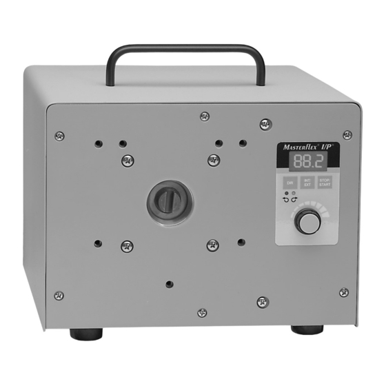
77411-00 pump drive
Model Nos.
N° de modèle
Modellnummer
Número de modelo
Modello nº
77410-10
77411-00
1-800-MASTERFLEX (627-8373) (U.S. and Canada only) • 11 (847) 549-7600 (Outside U.S.)
(847) 549-7600 (Local) • www.masterflex.com • techinfo@coleparmer.com
Thermo Fisher Scientific
1-800-637-3739 (U.S. and Canada only) • 11 (847) 381-7050 (Outside U.S.)
(847) 381-7050 (Local) • www.thermoscientific.com • fluidhandling@thermoscientific.com
®
OPERATING MANUAL:
PUMP DRIVES
MODE D'EMPLOI:
ENTRAÎNEMENTS
DE POMPES
BETRIEBSANLEITUNG:
PUMPENANTRIEBE
MANUAL DE FUNCIONAMIENTO:
MOTOR DE BOMBAS
MANUALE DI ISTRUZIONI:
UNITÀ DI
CONTROLLO POMPA
®
A-1299-1037
Edition 05
Chapitres
Table des Matières
Dépannage

Manuels Connexes pour Masterflex 77410-10


Sommaire des Matières pour Masterflex 77410-10
-
Page 12: Avertissements
® ® TABLE DES MATIÈRES Titre SÉCURITÉ ..................INTRODUCTION . -
Page 13: Introduction
INTRODUCTION Cet entraînement sans balais contrôle la vitesse des Têtes de Pompe MASTERFLEX I/P et offre des débits variables allant de 0,2 à 17 l/mn (0,06 à 4,5 gpm). Atteignez jusqu’à 26 l/mn (7 gpm) avec deux Têtes de Pompe empilées Standard ou EASY-LOAD I/P. -
Page 14: Montage Et Fonctionnement De L'entraînement
® ® MONTAGE ET FONCTIONNEMENT DE l’ENTRAÎNEMENT 1. Branchez toutes les connexions de commande externes. (Modèle 77411-00 uniquement) 2. Montez la Tête de Pompe et chargez les tubes (voir manuel de la Tête de Pompe). REMARQUE : La pompe Haute Performance I/P est montée avec les tubes sur la gauche. La pompe Standard I/P est montée avec les tubes vers le haut. -
Page 15: Commande À Distance
® ® COMMANDE À DISTANCE (Modèle 77411-00 uniquement) ● Entrée sélectionnable (4-20 mA, 0-10V DC) ● Commande de linéarité ±0.5% ● Gamme commune de ±50V eu égard à la prise de terre ● START/STOP (MARCHE/ARRÊT) Interne et Externe ; CW/CCW (Sens des aiguilles d’une montre/ Sens inverse) par fermeture de contact. - Page 16 ® ® 17 18 Figure 2 ROUGE/JAUNE REMARQUE : Les couleurs sont celles BLEU du câbles de la commande à distance. Numéro Catalogue 77300-32 VERT EXTERNAL EXTERNAL INTERNAL GRIS START/STOP CW/CCW START/STOP – – – BRUN JAUNE (RÉSERVÉ) ROSE BLANC N.O.
-
Page 17: Dépannage Et Entretien
® ® DÉPANNAGE ET ENTRETIEN REMPLACEMENT DE FUSIBLE 1 Placez l’interrupteur électrique en position “off”. 2 Débranchez le cordon d’alimentation depuis la ligne et la prise femelle. 3 Retirez et vérifiez le fusible, remplacez-le s’il est défectueux. 4 Rebranchez le cordon d’alimentation à la prise femelle. Figure 3 Fusible T6.3A (Attention : Ne pas remplacer par un autre type.) -
Page 18: Dépannage (Suite)
® ® DÉPANNAGE (Suite) Si un message d’erreur s’affiche, reportez-vous à la liste suivante pour déterminer les actions correctives à entreprendre. Si ceci ne corrige pas le problème, contactez votre vendeur. MESSAGE D’ERREUR CAUSE SOLUTION “Err 2” Survitesse moteur 1 Annulez en appuyant sur une touche 2 Vérifiez que le tube se remplit correctement et que la pompe fonctionne 3 Envoyez l’appareil en réparation si l’erreur persiste... -
Page 19: Spécifications
® ® SPÉCIFICATIONS SORTIE Vitesse : 33 à 650 T/MN Couple de sortie, maximum : Continu 540 oz-in (39 kg-cm) à 25°C Ambiant 380 oz-in (27 kg-cm) à 40°C Ambiant Démarrage 960 oz-in (69 kg-cm) Réglage de vitesse : Conduite ±0.25% F.S. -
Page 20: Garantie
® GARANTIE Utilisez uniquement des conduites de précision MASTERFLEX avec des pompes MASTERFLEX pour assurer des performances optimales. L’utilisation d’autres conduites peut annuler la garantie. Nous garantissons que ce produit est conforme aux descriptifs. Si une réparation ou un réglage s’avère nécessaire durant la période de garantie, le problème sera corrigé...