Table des Matières

Publicité

Les langues disponibles

Les langues disponibles

Liens rapides

Curtarolo (Padova) Italy
www.avselectronics.com
MANUALE GENERALE
INSTALLAZIONE
PROGRAMMAZIONE
Sistema di qualità
ISO 9001:2008
IST0755V3.3
DI
E
certificato
- 1 -
I
T
A
E
N
G
F
R
A

Publicité

Table des Matières
loading

Sommaire des Matières pour AVS Electronics Lucky 4

  • Page 1 Curtarolo (Padova) Italy www.avselectronics.com MANUALE GENERALE INSTALLAZIONE PROGRAMMAZIONE Sistema di qualità certificato ISO 9001:2008 IST0755V3.3 - 1 -...
  • Page 2: Table Des Matières

    L’apparecchio non dev’essere sottoposto a stillicidio o spruzzi d’acqua e nessun oggetto pieno di liquido dev’essere posto su di esso. AVS ELECTRONICS S.p.a. si riserva il diritto di apportare modifiche in qualsiasi momento e senza preavviso. INSTALLAZIONE E MANUTENZIONE DEVONO ESSERE FATTE DA PERSONALE...
  • Page 3: I T A

    Contenitore Antistrappo Predisposizione per fissaggio a muro Predisposizione per ingresso cavi Vite di chiusura Antistrappo Tamper Punto di fissaggio 1. Forare in corrispondenza cavi alimentazione del riferimento -1- Piano di appoggio 2. Staccare il distanziale -2- per la batteria 3. Inserire il tassello e serra- re la vite -3- Predisposizione per 4.
  • Page 4: Generalità Lucky 4

    – memorizzazioni - esclusioni degli ingressi – attivazione – spegnimento – presenza rete – batteria bassa. Ha inoltre la possibilità di avere delle uscite ausiliarie (Open Collector) per il controllo dello stato delle zone e della batteria. Caratteristiche tecniche LUCKY 4 • °...
  • Page 5: Generalità Lucky 8

    Generalità LUCKY 8 Centrale a microprocessore di AVS, ideale per impianti di medie dimensioni, di semplice utilizzo. Permette la gestione di una linea Tamper, di 8 ingressi e di una accensione con un lettore di prossimità posto in centrale (tramite il quale si può anche modificare la programmazione). E’...
  • Page 6: Scheda Della Centrale

    Linee di ingresso La scheda principale, ha complessivamente n. 4 ingressi di zona (L1 - L4) per LUCKY 4 e n. 8 ingressi di zona (L1 - L8) per LUCKY8, n. 1 ingresso dedicato alla protezione antimanomissione (T T). E’...
  • Page 7: Ingressi E Uscite Ausiliarie

    Ingressi e uscite ausiliarie In morsettiera: AOAH B AO: (Accensione On) Ingresso ausiliario di accensione ON del Settore 1: collegandolo al negativo, il settore 1 si accende in ON; lasciandolo libero, il settore 1 risulta spento. Nel caso in cui vengano usate anche la chiavi elettroniche, bisogna tener conto che le due accensioni, esterna da morsetto ON e quella da chiave elettronica, si sommano;...
  • Page 8: Lettori Seriali Rs

    Lettori seriali RS I lettori RS si collegano direttamente sulla seriale RS485 e permettono di effettuare le operazioni di accensione/spegnimento del settore a cui sono associati. Grazie al riconoscimento del lettore sul quale stiamo operando è possibile effettuare, con una opportuna configurazione, delle operazioni diversificate.
  • Page 9: Visualizzazioni Su Inseritori Rs

    Visualizzazioni su inseritori RS Led Verde Led 1° Rosso Led 2° Rosso Led 3° Rosso i t n e t l i t a i ' l i t t è a l l i ' l l t a l i v i a l l l l a...
  • Page 10: Funzioni Led, Pulsante Pb E Lettore Rd

    Led: Nel normale funzionamento della centrale i led hanno il seguente comportamento: • Lucky 4 : L1 - L4 stato delle zone: Spento se la zona è a riposo Lampeggiante veloce se la zona è andata in allarme nell’ul- •...
  • Page 11: Programmazione

    PROGRAMMAZIONE 1. Led di zona 2. Inseritore RS 3. Pulsante PB 4. Led accensione 5. Led Tamper 6. Led Batteria 7. Led Presenza rete USCITE Dip Switch STATO Ponte S1 F 2A 1 2 3 4 5 6 7 8 Inseritore RS Ponte S2 T 0.63 A...
  • Page 12: Tempo Attivazione Relè Di Allarme

    Batteria. Al termine del lampeggio del led Batteria, il Tamper centrale e la zona 1 se programmata come 24 h vengono riattivati. Acquisizione chiavi di prossimità (massimo 8 per Lucky 4 e massimo 16 per Lucky 8) Durante questa procedura vengono acquisiti anche tutti gli inseritori RS collegati alla seriale RS485 Nella scheda della centrale chiudere il ponte S1 nella posizione 4 Avvicinare la chiave da acquisire ad un inseritore associato al settore in cui deve operare.
  • Page 13: Cancellazione Chiavi Di Prossimità

    Premere ripetutamente il pulsante PB fino ad ottenere il grado di sensibilità desiderato visualizzato dall’accensione dei led di zona da 1 a 4 in Lucky 4 e da 1 a 7 in Lucky 8, tenendo conto che maggiore è il numero di led di zona accesi e minore è la sensibilità.
  • Page 14: Schema Di Collegamento Lucky 4 Con Dip 5 In On

    Schema di collegamento LUCKY 4 con Dip 5 in ON T 0.63 A DIP 5 in OFF Con linee normalmente chiu- se, seguire lo schema senza collegare le resistenze di IN ALIM. bilanciamento L1 L2 L8 T T AO AH B...
  • Page 15: Schema Di Collegamento Lucky 8 Con Dip 5 In On

    Schema di collegamento LUCKY 8 con Dip 5 in ON T 0.63 A DIP 5 in OFF Con linee normalmente chiu- se, seguire lo schema senza collegare le resistenze di IN ALIM. bilanciamento L1 L2 L8 T T AO AH B SAC NCNO RS 485 LINEE...
  • Page 16 Via Valsugana, 63 35010 (Padova) ITALY Tel. +39 049 9698 411 / Fax. +39 049 9698 407 avs@avselectronics.it www.avselectronics.com Assistenza Tecnica: +39 049 9698 444 support@avselectronics.it - 16 -...
  • Page 17 Curtarolo (Padova) Italy www.avselectronics.com GENERAL MANU GENERAL MANU GENERAL MANU AL GENERAL MANU GENERAL MANU INST INST ALLA ALLA TION TION INST INST ALLA INST ALLA ALLA TION TION TION OGRAMMING OGRAMMING PR OGRAMMING OGRAMMING OGRAMMING Certified Quality System ISO9001:2008 IST0755V3.3 - 17 -...
  • Page 18 Input in Programming, second level: ..................pag. 28 Leaving programming, second level ..................pag. 28 Acquisition of proximity keys (max 8 for Lucky 4 and max 16 for Lucky 8):....pag. 28 Cancellation of proximity keys ..................pag. 29 Association of zones to arming and/or areas ..............pag. 29 Adjustment of switch alarm zones ..................pag.
  • Page 19: E N G

    Housing Anti-tamper Predisposition for fixation to wall Predisposition for cables entry Closing screw Anti-tamper Fixation point of the supplying cables 1. Drill in correspondence of reference -1- Battery location 2. Detach the spacer -2- Predisposition for 3. Insert the screw and fixation to wall tighten -3- 4.
  • Page 20: Lucky 4 General Features

    LUCKY 4 General Features AVS microprocessor control panel, ideal for small/medium size installations and easy to use It has a tamper line, 4 inputs and 1 arming mode by a proximity reader placed on control panel (also allowing to modify programming).
  • Page 21: Lucky 8 General Features

    LUCKY 8 General Features AVS microprocessor control panel, ideal for small/medium size installations and easy to use It has a tamper line, 8 inputs and 1 arming mode by a proximity reader placed on control panel (also allowing to modify programming). By use of max 8 transponder readers in-series-connected, it is possible to manage an area with three arming modes (Total + 2 partials) with automatic partialization of the zones or it is possible to share the system into two independent areas.
  • Page 22: Control Panel Board

    Inputs zones Main board has a total of 4 zone inputs (L1 – L4) for Lucky 4 and 8 zone inputs (L1 – L8) for Lucky8, 1 dedicated input for tamper protection (TT). A supplying output V Linee is available, protected by a fuse of 0,63 A.
  • Page 23: Inputs And Additional Outputs

    Inputs and additional outputs On terminal board: AOAH B AO:(Arming ON) additional arming input on of area 1: connecting it to negative; the area 1 is armed in ON; leaving it free, the area 1 is off. In case electronic keys are also used, consider that the two arming, the external one from terminal ON and the one from the electronic key, add up;...
  • Page 24: Serial Reader Rs

    Serial reader RS The RS readers are to be connected directly to the serial RS485 and allow to make the operations of arming/disarming of the area to which they are associated. Thanks to recognition of the reader on which we are operating, it is possible to make, with a correct configuration, various operations.
  • Page 25: Visualizations On Rs Readers

    Visualizations on RS readers Green Led Led 1 Red Led 2 Red Led 3 Red g i l e t l i t a i t c i l b i l b , y l l a t t a l i l b t i n i l b...
  • Page 26: Led Functions, Pb Pushbutton And Rd Reader

    Led functions, PB pushbutton and RD reader Led: During normal working of control panel, led behave as follows: • Lucky 4 : L1 - L4 zones status : Off if the zone is quiet Quickly blinking if the zone has been in alarm during last •...
  • Page 27: Programming

    PROGRAMMING 1. Zone LED 2. RS Reader 3. PB pushbutton 4. Arming LED 5. Tamper LED 6. Battery LED 7. Mains presence LED USCITE Dip Switch STATO Jumper S1 F 2A 1 2 3 4 5 6 7 8 Reader RS Jumper S2 T 0.63 A FIRST LEVEL PROGRAMMING (THROUGH DIP-SWITCH):...
  • Page 28: Alarm-Relay Activation Time

    1 if programmed as 24 hours, are re- activated. Acquisition of proximity keys (max 8 for Lucky 4 and max 16 for Lucky 8): During this procedure, all RS readers connected to RS485 serial are acquired.
  • Page 29: Cancellation Of Proximity Keys

    Press pushbutton PB several times until reaching the level sensitivity wished, visualized by lighting up of zone led from 1 to 4 on Lucky 4 and from 1 to 7 on Lucky 8, and keeping in mind that the bigger is the number of led ON the lower is the sensitivity.
  • Page 30: Connection Scheme Lucky4 With Dip5 In On

    Connection scheme LUCKY4 with Dip5 in ON T 0.63 A DIP 5 in OFF With normally closed inputs, follow the scheme without connecting the balance IN ALIM. resistances L1 L2 L8 T T AO AH B SAC NCNO RS 485 LINEE TAMPER VLINEE VPOT...
  • Page 31: Connection Scheme Lucky8 With Dip5 In On

    Connection scheme LUCKY8 with Dip5 in ON T 0.63 A DIP 5 in OFF With normally closed inputs, follow the scheme without connecting the balance IN ALIM. resistances L1 L2 L8 T T AO AH B SAC NCNO RS 485 LINEE TAMPER VLINEE VPOT...
  • Page 32 Via Valsugana, 63 35010 (Padova) ITALY Tel. +39 049 9698 411 / Fax. +39 049 9698 407 avs@avselectronics.it www.avselectronics.com support@avselectronics.it - 32 -...
  • Page 33 Curtarolo (Padova) Italy www.avselectronics.com MANUEL GENERAL D’INSTALLATION DE PROGRAMMATION Systeme Qualitè Certifie ISO9001:2008 IST0755V3.3 - 33 -...
  • Page 34 Entrèe en programmation de 2ND niveau ................pag. 44 Sortie de la programmation de 2nd niveau ................pag. 44 Acquisition clé de proximité (maximum 8 pour la Lucky 4 et 16 pour la Lucky 8): ..pag. 44 Annulation clé de proximité ....................pag. 45 Association zone aux Mises En Service et/ou aux secteurs.
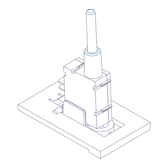
  • Page 35: F R A

    Boitier Anti-arrachage Prédisposition pour fixation au mur Prédisposition pour entrée câble Vis de fermeture Anti-arrachage Sabotage Point de fixation Percer en face de la Point de fixation câbles alimentation référence – 1 – câbles alimentation Détacher le Plan d’appui distanciateur -2 – pour la batterie Insérer la cheville et Prédisposition pour...
  • Page 36: Généralité Lucky 4

    ; alarmes – mémorisation – exclusion des entrées – Mises En Service – Mises Hors Service – présence réseau – batterie basse. En plus, LUCKY 4 intègre des sorties auxiliaires (Open Collector) pour le contrôle de l’état des zones et de la batterie.
  • Page 37: Généralité Lucky 8

    ; alarmes – mémorisation – exclusion des entrées – Mises En Service – Mises Hors Service – présence réseau – batterie basse. En plus, LUCKY 4 intègre des sorties auxiliaires (Open Collector) pour le contrôle de l’état des zones et de la batterie.
  • Page 38: Carte De La Centrale

    La carte principale a en tout et pour tout 1 entrée dédiée à la protection sabotage (T T), plus - pour la LUCKY 4 - 4 entrées de zone (L1-L4) ou - pour la LUCKY 8 - 8 entrées de zone. Une sortie d’alimentation protégée par fusible F3 de 0,63 A VLINEE est disponible.
  • Page 39: Entrées Et Sorties Auxiliaires

    Entrées et sorties auxiliaires Aux bornes: AOAH B AO : (MES ON ) Entrée auxiliaire de MES ON du secteur 1 : en le reliant au négatif, le secteur 1 s’active en ON ; en le laissant libre, le secteur 1 sera Mis Hors Service (MHS). Dans le cas où sont également utilisées des clés électroniques, se rappeler que les 2 Mises En Service (externe sur borne ON et celle par clé...
  • Page 40: Lecteur Série Rs

    Lecteur série RS Les lecteurs série RS se connectent directement sur un bus série RS485 et permettent d’effectuer les opérations de Mise En/Hors Service des secteurs pour lesquelles elles sont associées. Grâce à l’opération adéquate, la reconnaissance du lecteur par lequel nous effectuons l’opération permet d’effectuer des actions diverses.
  • Page 41: Visualisation Sur Lecteurs Rs

    Visualisation sur lecteurs RS Led Vert Led rouge ème Led Rouge ème Led Rouge i v r i v r i v r e i t i v r e i t u l l è i e t l i t a f i t g i l...
  • Page 42: Fonctionnement Led, Bouton Pb, Et Lecteur Rd

    Pendant le fonctionnement normal de la centrale, les leds ont le comportement suivant : • Lucky 4 : L1 - L4 état des zones : Éteint si la zone est au repos Clignotement rapide si la zone a été en alarme lors de la •...
  • Page 43: Programmation

    PROGRAMMATION Led de zone Lecteur RS Bouton PB Led de Mise En Service Led de sabotage (Tamper) Led de Batterie Led de présence Réseau USCITE Dip switch STATO Pont S1 F 2A 1 2 3 4 5 6 7 8 Lecteur RS Pont S2 T 0.63 A...
  • Page 44: Temps D'activation Du Relai D'alarme

    Led Batterie, le sabotage (Tamper) de la centrale (et la zone 1, quand programmée en zone 24 heures) sont réactivés. Acquisition clé de proximité (maximum 8 pour la Lucky 4 et 16 pour la Lucky 8): Tous les lecteurs RS connectés au bus série RS485 sont également mémorisés lors de cette procédure.
  • Page 45: Annulation Clé De Proximité

    Presser plusieurs fois le bouton PB, pour obtenir le degré de sensibilité désiré, représenté par l’allumage des led des zones de 1 à 4 pour la Lucky 4 et de 1 à 7 pour la Lucky 8, en se rappelant que la sensibilité...
  • Page 46: Schéma De Connexion Lucky 4 Avec Dip 5 En On

    Schéma de connexion LUCKY 4 avec Dip 5 en ON T 0.63 A DIP 5 en OFF Suivre le schéma sans placer les résistances d’équilibrage si les zones sont IN ALIM. Normalement Fermées. L1 L2 L8 T T AO AH B...
  • Page 47: Schéma De Connexion Lucky 8 Avec Dip 5 En On

    Schéma de connexion LUCKY 8 avec Dip 5 en ON T 0.63 A DIP 5 en OFF Suivre le schéma sans placer les résistances d’équilibrage si les zones sont IN ALIM. Normalement Fermées. L1 L2 L8 T T AO AH B SAC NCNO RS 485 LINEE...
  • Page 48 Via Valsugana, 63 35010 (Padova) ITALY Tel. +39 049 9698 411 / Fax. +39 049 9698 407 avs@avselectronics.it www.avselectronics.com support@avselectronics.it - 48 -...

Ce manuel est également adapté pour:

Lucky 8

Table des Matières