Table des Matières

Manuels Connexes pour Power Fist CETL 3072101


Sommaire des Matières pour Power Fist CETL 3072101
- Page 1 All manuals and user guides at all-guides.com V 3.05 8507667 Mini Milling Machine User Manual Please read and understand all instructions before use. Retain this manual for future reference.
- Page 2 All manuals and user guides at all-guides.com V 3.05 8507667 Mini Milling Machine SPECIFICATIONS CETL CETL 3072101 Speed 100 to 1,100 RPM (low range), 100 to 2,500 RPM (high range) T-slots 1/2 in. Spindle Taper Table Size 15-3/8 x 3-5/8 in.
-
Page 3: Important Safety Precautions
All manuals and user guides at all-guides.com 8507667 Mini Milling Machine V 3.05 IMPORTANT SAFETY PRECAUTIONS WARNING! Read and understand all instructions before using this tool. The operator must follow basic precautions to reduce the risk of personal injury and/or damage to the equipment. Before allowing someone else to use this tool, make sure they are aware of all safety information. -
Page 4: Electrical Safety
All manuals and user guides at all-guides.com V 3.05 Mini Milling Machine 8507667 8. Do not touch the cutter or the surface that has been cut with this tool immediately after use. The surface will be hot and may cause an injury. 9. - Page 5 All manuals and user guides at all-guides.com 8507667 Mini Milling Machine V 3.05 VIBRATION PRECAUTIONS This tool / work piece vibrates during use. Repeated or long-term exposure to vibration may cause temporary or permanent physical injury, particularly to the hands, arms and shoulders. 1.
-
Page 6: Parts Identification
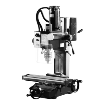
All manuals and user guides at all-guides.com V 3.05 Mini Milling Machine 8507667 PARTS IDENTIFICATION Motor Fine Feeding Wheel Headstock & Spindle Longitudinal Feed Hand Wheel Working Table Saddle Cross Feed Hand Wheel Base Connecting Strut Limit Block Controller Balance Mechanism Fuselage Electrical Box Accessories... - Page 7 All manuals and user guides at all-guides.com 8507667 Mini Milling Machine V 3.05 INSTALLATION 1. The tool should be secured to a work table with four hexagon bolts. Select an appropriate location to securely fasten to tool that is solid, stable and level.
-
Page 8: Electrical Circuit Diagram
All manuals and user guides at all-guides.com V 3.05 Mini Milling Machine 8507667 Removal CAUTION! Remove the unit from its power source before changing any accessories. 1. Remove the protective cover. 2. Insert the fixing pin into the spindle. 3. Use the #14 open end wrench to loosen (counter clockwise) the spindle nut, loosening the tapered shank. 4. - Page 9 All manuals and user guides at all-guides.com 8507667 Mini Milling Machine V 3.05 220 to 240V OPERATION NOTE: Practice on a scrap piece of material before attempting to work on the actual work piece. Using the tool successfully requires a considerable degree of acquired skill and experience. CAUTION! During operation, if any unusual situations occur, stop the machine immediately and have the unit serviced by a qualified service technician.
- Page 10 All manuals and user guides at all-guides.com V 3.05 Mini Milling Machine 8507667 TRAVEL ADJUSTMENT Using the limit block can control the amount of motion of the spindle box. 1. Loosen the handle (a) beside the limit block (b). 2. Move the limit block (b) into the desired position. 3.
- Page 11 All manuals and user guides at all-guides.com 8507667 Mini Milling Machine V 3.05 BEFORE SWITCHING ON THE UNIT 1. Remove all adjusting keys and wrenches. 2. Confirm that the power voltage is suitable for the tool. 3. Remove any obstacles in the work area that could obstruct the usage of the tool. 4.
-
Page 12: Pre-Operation
All manuals and user guides at all-guides.com V 3.05 Mini Milling Machine 8507667 PRE-OPERATION Before you turn the power on: 1. Check that the tool chuck and cutter are tightly secured. 2. Check each machine part to confirm that no parts are loose. 3. - Page 13 All manuals and user guides at all-guides.com 8507667 Mini Milling Machine V 3.05 FACE MILLING 1. According to the Installation And Removal Of The Tapered Shank section, install the appropriate accessory and tighten securely. 2. Select the appropriate speed level. CAUTION! Do Not change the High / Low speed setting while the spindle is running.
-
Page 14: Lubrication
All manuals and user guides at all-guides.com V 3.05 Mini Milling Machine 8507667 6. Use the wrenches provided with the unit. Do not make adjustments to the machine with unsuitable tools. Do not use a hammer to strike the wrench in order to tighten components. Damage could result leading to product failure. -
Page 15: Parts Breakdown
All manuals and user guides at all-guides.com 8507667 Mini Milling Machine V 3.05 PARTS BREAKDOWN PARTS LIST Description Qty. Description Qty. Base Holding Plate (1) Dust Guard Cover X Axis Feeding Screw Holding Plate (2) Key 4x16 Ball Bearing 8200 Dial Washer Hand Wheel... - Page 16 All manuals and user guides at all-guides.com V 3.05 Mini Milling Machine 8507667 Description Qty. Description Qty. Y Axis Bearing Seat Screw Seat Working Table Cap Screw M6x16 Y Axis Feeding Screw Set Screw M6x22 End Cover Nut M6 Screw M6x10 Limit Block Handle Y Axis Screw Nut Screw M6x10...
- Page 17 All manuals and user guides at all-guides.com 8507667 Mini Milling Machine V 3.05 Visit www.princessauto.com for more information...
- Page 18 All manuals and user guides at all-guides.com V 3.05 Mini Milling Machine 8507667 Description Qty. Description Qty. Saddle Connecting Strut Y Axis Wedge Key 5x5x40 X Axis Screw Nut Spindle Cap Screw M6x25 Transmission Gear Fuselage Seat Support Block 39-1 Shaft Screw M5x20 39-2...
- Page 19 All manuals and user guides at all-guides.com 8507667 Mini Milling Machine V 3.05 Description Qty. Description Qty. Cap Screw M5x8 Warning Label Bearing Cover PC Board Ball Bearing 80206 Locking Sleeve Name Plate Rotor Shaft Label key 4x6 Protective Cover Spring Support Motor Torsion Spring...
- Page 20 All manuals and user guides at all-guides.com V4.0 8507667 Mini Milling Machine - Addendum INSTALLATION INTRODUCTION REMOVAL WARNING! Remove the unit from its power source before Follow Steps 1 and 3 for Installation. You can use the mini milling machine as a drill press or as changing any accessories.
- Page 21 All manuals and user guides at all-guides.com V 3,05 8507667 Mini fraiseuse Manuel d'utilisateur Vous devez lire et comprendre toutes les instructions avant d'utiliser l'appareil. Conservez ce manuel afin de pouvoir le consulter plus tard.
- Page 22 All manuals and user guides at all-guides.com V 3,05 8507667 Mini fraiseuse SPÉCIFICATIONS CETL CETL 3072101 Vitesse 100 à 1 100 TPM (basse vitesse), 100 à 2 500 TPM (haute vitesse) Fentes en T 1/2 po Broche conique Dimensions de la table 15 3/8 x 3 5/8 po Distance max.
-
Page 23: Consignes De Sécurité Importantes
All manuals and user guides at all-guides.com 8507667 Mini fraiseuse V 3,05 CONSIGNES DE SÉCURITÉ IMPORTANTES AVERTISSEMENT ! Veuillez lire et comprendre toutes les instructions avant d’utiliser cet outil. L’utilisateur doit respecter les précautions de base lorsqu’il utilise cet outil afin de réduire le risque de blessure ou de dommage à... -
Page 24: Consignes De Sécurité Spécifiques
All manuals and user guides at all-guides.com V 3,05 Mini fraiseuse 8507667 CONSIGNES DE SÉCURITÉ SPÉCIFIQUES 1. N’approchez pas les mains de la zone de coupe ou de la lame. Si vous tenez l’outil avec les deux mains, la lame ne peut les couper. 2. -
Page 25: Précautions Relatives Aux Vibrations
All manuals and user guides at all-guides.com 8507667 Mini fraiseuse V 3,05 8. Disposez le cordon électrique de façon qu’il ne touche pas l’outil et qu’il ne risque pas de se prendre dans la pièce à travailler. Le cordon doit toujours se trouver derrière l’outil. 9. -
Page 26: Déballage
All manuals and user guides at all-guides.com V 3,05 Mini fraiseuse 8507667 DÉBALLAGE 1. Retirez soigneusement l’outil de l’emballage et conservez les matériaux d’emballage jusqu’à ce que vous ayez inspecté avec soin et installé ou utilisé l’outil de manière satisfaisante. 2. -
Page 27: Installation Et Dépose De La Tige Biseautée
All manuals and user guides at all-guides.com 8507667 Mini fraiseuse V 3,05 INSTALLATION 1. L’outil doit être retenu sur une table de travail au moyen de quatre boulons hexagonaux. Choisissez un endroit approprié qui est solide, stable et de niveau afin d’y fixer l’outil. REMARQUE : Évitez de placer l’appareil sous les rayons directs du soleil ou dans un environnement humide ou poussiéreux. - Page 28 All manuals and user guides at all-guides.com V 3,05 Mini fraiseuse 8507667 Dépose ATTENTION ! Enlevez l’appareil de sa source d’énergie avant de remplacer quelque accessoire que ce soit. 1. Enlevez le couvercle de protection. 2. Insérez la tige de fixation dans la broche. 3.
-
Page 29: Diagramme Du Circuit Électrique
All manuals and user guides at all-guides.com 8507667 Mini fraiseuse V 3,05 DIAGRAMME DU CIRCUIT ÉLECTRIQUE 110 à 115 V Visitez www.princessauto.com pour plus d'informations... - Page 30 All manuals and user guides at all-guides.com V 3,05 Mini fraiseuse 8507667 220 à 240 V En cas de questions techniques, appelez le 1-800-665-8685...
-
Page 31: Utilisation
All manuals and user guides at all-guides.com 8507667 Mini fraiseuse V 3,05 UTILISATION REMARQUE : Pratiquez sur une pièce de rebut avant de tenter l’opération sur la pièce à travailler véritable. L’utilisation réussie de l’outil demande un degré considérable de compétences et d’expérience. ATTENTION ! Si une situation inhabituelle survient en cours de marche, arrêtez immédiatement l’appareil et confiez-le à... -
Page 32: Avant D'actionner L'appareil Fig
All manuals and user guides at all-guides.com V 3,05 Mini fraiseuse 8507667 3. Serrez ou ajustez les vis de réglage en vous rappelant que la pression doit être identique au niveau de chacune des vis. 4. Ajustez la partie médiane en premier lieu en progressant de façon uniforme vers l’intérieur à... -
Page 33: Après Le Démarrage Initial
All manuals and user guides at all-guides.com 8507667 Mini fraiseuse V 3,05 5. Laissez l’appareil fonctionner pendant un total de cinq minutes au cours desquelles vous augmenterez graduellement la vitesse de la broche à son maximum. Laissez l’appareil fonctionner pendant au moins deux minutes à... -
Page 34: Entretien
All manuals and user guides at all-guides.com V 3,05 Mini fraiseuse 8507667 6. Enlevez les outils de réglage et tous les obstacles pouvant se trouver autour de l’appareil. 7. Activez l’alimentation principale. Ajustez la broche à la vitesse désirée pour le perçage ou un fraisage profond. -
Page 35: Entretien De L'outil De Coupe
All manuals and user guides at all-guides.com 8507667 Mini fraiseuse V 3,05 ENTRETIEN DE L’OUTIL DE COUPE REMARQUE : Arrêtez l’appareil et coupez la source d’énergie avant de procéder à toute opération d’inspection ou d’entretien. 1. Portez des gants de protection ou utilisez un chiffon pour manipuler l’outil de coupe afin de prévenir ainsi toute blessure corporelle. -
Page 36: Répartition Des Pièces
All manuals and user guides at all-guides.com V 3,05 Mini fraiseuse 8507667 RÉPARTITION DES PIÈCES LISTE DES PIÈCES Description Qté Description Qté Base Plaque de retenue (1) Vis d’alimentation sur l’axe X Couvercle de protection antipoussière Clé 4x16 Plaque de retenue (2) Cadran Roulement à... - Page 37 All manuals and user guides at all-guides.com 8507667 Mini fraiseuse V 3,05 Description Qté Description Qté Vis de calage M6x22 Siège de roulement sur l’axe Y Écrou M6 Table de travail Vis d’alimentation sur l’axe Y Poignée de bloc de limitation Couvercle d’extrémité...
- Page 38 All manuals and user guides at all-guides.com V 3,05 Mini fraiseuse 8507667 En cas de questions techniques, appelez le 1-800-665-8685...
- Page 39 All manuals and user guides at all-guides.com 8507667 Mini fraiseuse V 3,05 Description Qté Description Qté Siège de fuselage Bloc de support 39-1 Arbre Vis M5x20 39-2 Clé 8x12 Goupille 4x15 Rondelle à ressort 10 Vis sans fin 40-1 Rondelle 10 Manchon Vis d’assemblage M10x30 Goupille 3x12...
- Page 40 All manuals and user guides at all-guides.com V 3,05 Mini fraiseuse 8507667 Description Qté Description Qté Étiquette Manchon de verrouillage Couvercle de protection Arbre de rotor Moteur Clé 4x6 127A Goupille Support de ressort 127B Rondelle Ressort de torsion Engrenage de moteur 21/29T Couvercle Anneau interne Écrou...
- Page 41 All manuals and user guides at all-guides.com V 4,0 8507667 Mini fraiseuse - Addenda Support de couvercle puisque la pression latérale pendant le découpage peut INTRODUCTION endommager la fraise en bout et la pince de serrage. antipoussière Vous pouvez utiliser la mini fraiseuse comme une Vissez la pince de serrage directement dans le tirant Couvercle antipoussière perceuse à...