Table des Matières
Publicité
Les langues disponibles
Les langues disponibles
Liens rapides
FAUCHEUSE A FLÉAUX
FLAIL MOWER
696 route de Beauregard 39570 COURBOUZON
Tél. 03 84 47 03 23 - Fax. 03 84 24 61 99
E-mail : info@kiva.fr - Web : www.kiva.fr
MAXIMA
Manuel d'utilisation - Notice originale
FR
Instruction for use - Original notice
EN
- Lire les instructions du manuel utilisateur, ainsi que les consignes de sécurité. Se familiariser avec le
fonctionnement et les commandes de la faucheuse à fléaux avant utilisation.
- Read the instruction manual, and also the safety instructions. Familiarise yourself with how the flail
mower and its controls work, before using it.
0 /20
Publicité
Chapitres
Table des Matières

Manuels Connexes pour Kiva MAXIMA


Sommaire des Matières pour Kiva MAXIMA
- Page 1 FLAIL MOWER 696 route de Beauregard 39570 COURBOUZON Tél. 03 84 47 03 23 - Fax. 03 84 24 61 99 E-mail : info@kiva.fr - Web : www.kiva.fr MAXIMA Manuel d’utilisation - Notice originale Instruction for use - Original notice - Lire les instructions du manuel utilisateur, ainsi que les consignes de sécurité.
-
Page 2: Table Des Matières
SOMMAIRE Pages Description ......... . Plaque d’identification de la machine . -
Page 3: Description
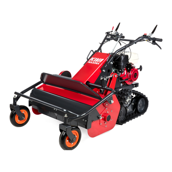
DESCRIPTION 1. Guidon 2. Commande de gaz 3. Levier de verrouillage d’embrayage des couteaux 4. Levier d’embrayage des couteaux 5. Contacteur marche/arrêt 6. Réservoir carburant 7. Lanceur 8. Manivelle de réglage hauteur de coupe 9. Volets de protection 10. Roues avant 11. -
Page 4: Caractéristiques Techniques
CARACTÉRISTIQUES TECHNIQUES Longueur / Largeur / Hauteur de la machine 1800 mm / 1000 mm / 1050 mm Distance entre les roues 650 mm Poids 248 Kg HONDA GX270 Modèle moteur Type de moteur Essence 4 temps OHV refroidi par air 270 cc Cylindrée Puissance continue... -
Page 5: Conseils D'utilisation De Sécurité Et D'entretien
CONSEILS D’UTILISATION DE SÉCURITÉ ET D’ENTRETIEN - Tirer la machine vers soi ou inverser le sens de marche (si disponible) avec beau- coup de précaution. Attacher une attention particulière aux indications précédées des mentions suivantes: - Conserver la distance de sécurité par rapport aux outils rotatifs, donnée par la lon- gueur du guidon. -
Page 6: A1 - Déballage
PRÉPARATION DE LA MACHINE DÉBALLAGE FAUCHEUSE A FLÉAUX FLAIL MOWER Manuel d’utilisation Instruction for use - Lire les instructions du manuel utilisateur, ainsi que les consignes de sécurité. Se familiariser avec le fonctionnement et les commandes de la faucheuse à fléaux avant utilisation. - Read the instruction manual, and also the safety instructions. -
Page 7: A3 - Plein D'huile Et Niveau Moteur
PRÉPARATION DE LA MACHINE PLEIN D’HUILE ET NIVEAU MOTEUR Avec la manivelle (1) ajuster IMPORTANT le réglage de la hauteur de coupe de la machine afin de positionner le moteur à l’ho- rizontale. Déposer le bouchon de remplissage (2) et mettre 1,1 litre d’huile SAE 10W-30 d’un rang supérieur à... -
Page 8: A6 - Réglage Du Guidon
PRÉPARATION DE LA MACHINE RÉGLAGE DU GUIDON Le réglage de la hauteur du guidon peut s’effectuer sur deux niveaux en changeant la position du trou de fixation arrière. Guidon fixé en position haute (2). Guidon fixé en position basse (1) lors de la livraison. INSTALLATION DES COUTEAUX Débrancher la bougie avant toute interven- tion sur les couteaux. -
Page 9: Fonctionnement
FONCTIONNEMENT DÉMARRAGE DU MOTEUR Avant d’utiliser la faucheuse à fléaux pour la première fois, étudier ce chapitre et liser attentivement. L’opérateur doit rester dans la zone de Ouvrir le robinet d’essence (1). Placer le levier de vitesse (2) au point sécurité... -
Page 10: B2 - Démarrage De La Machine Pour Le Déplacement
FONCTIONNEMENT DÉMARRAGE DE LA MACHINE POUR LE DÉPLACEMENT Régler le levier de régime moteur (4) sur Vérifier que le levier d’embrayage (3) est Placer le levier de vitesse (2) sur la position LENT. relâché sur ARRÊT. nécessaire pour le travail à effectuer. NOTA: N’utiliser le levier de vitesse que lorsque le levier d’embrayage se trouve en position... -
Page 11: B4 - Changement De Direction De La Machine
FONCTIONNEMENT CHANGEMENT DE DIRECTION DE LA MACHINE NOTA: En serrant ce levier (8) la machine effectue un changement de direction vers la gauche et si vous utilisez le levier (9) le changement de direction s’effectue vers la droite. Ces deux leviers ne doivent pas être utilisés en même temps. -
Page 12: D'embrayage
FONCTIONNEMENT ACCESSOIRES BLOCAGE DES ROUES AVANT Aucun accessoire n’est prévu sur cette machine. L’utilisation d’accessoires avec cette machine peut rendre la machine dangereuse, et occasionner des dommages sur votre machine qui ne seront pas couverts par votre garantie. Pour une progression régulière sur des ter- Positionner l’axe (12) dans le moyeu du rains en pente, bloquer les roues avant à... -
Page 13: Réglage Des Cables De Changement De Direction Droit Ou Gauche
MAINTENANCE ET CONTROLES A faire effectuer dans un atelier agréé. RÉGLAGE DES CABLES DE CHANGEMENT DE DIRECTION DROIT OU GAUCHE Arrêter le moteur et débrancher la bougie avant toute intervention. Lorsque le câble est trop tendu, il peut arriver que l’entraînement de la chenille de ce même coté... -
Page 14: C6 - Réglage Du Câble De Frein Des Fléaux
MAINTENANCE ET CONTROLES A faire effectuer dans un atelier agréé. RÉGLAGE DE LA COURROIE DES FLÉAUX Arrêter le moteur et débrancher la bougie avant toute intervention. (1) MAINTENANCE Retirer le capot latéral (19), et vérifier que la longueur du ressort (20) est de 68 à 71 mm entre les deux trous d’accroche. -
Page 15: C9 - Joint Spi Des Roues D'entraînement
MAINTENANCE ET CONTROLES A faire effectuer dans un atelier agréé. REMPLACEMENT DE LA CHENILLE Arrêter le moteur et débrancher la bougie avant toute intervention. Desserrer le contre-écrou (1), puis faire tourner le boulon de réglage (2) vers la gauche, et relâcher la tension de la chenille. Détender l’ensemble jusqu’à... -
Page 16: C11 - Remplacement Des Couteaux
MAINTENANCE ET CONTROLES A faire effectuer dans un atelier agréé. REMPLACEMENT DES COUTEAUX Arrêter le moteur et débrancher la bougie avant toute intervention. En cas d’usure de l’extrémité des couteaux et du tranchant, un rempla- cement par renversement est possible. Les couteaux (46 au total) sont installés sur leur support deux par deux, dos à... -
Page 17: C14 - Bougie D'allumage
MAINTENANCE ET CONTROLES A faire effectuer dans un atelier agréé. BOUGIE D’ALLUMAGE • Contrôler la bougie d'allumage au début de chaque période d’utilisation. • Régler l'intervalle de l’électrode à 0,7 mm et réinstaller la. Si le jeu devient supérieur à 0,7 mm, remplacer la bougie. •... - Page 18 CONTENTS Pages Description ......... . Machine identification plate .
-
Page 19: Description
DESCRIPTION 1. Handle 2. Accelerator control 3. Blades clutch lever locking 4. Blades clutch lever 5. Engine switch 6. Fuel tank 7. Recoil starter 8. Cutting height adjustment handle 9. Protection cover 10. Front tire 11. Left directing control 12. Rear or front clutch lever and parking brake 13. -
Page 20: Specifications
TECHNICAL SPECIFICATIONS Machine length / width / height 1800 mm / 1000 mm / 1050 mm Wheels distance 650 mm Weight 248 Kg Engine model Engine type Air-cooled, OH 4 stroke gasoline engine Capacity Continuous output 5,1 KW 3 00 rpm Maximum output 6, KW 3 00 rpm Fuel... -
Page 21: Safety Precautions
NSTRUCTIONS FOR USE - SAFETY AND MAINTENANCE - Take great care when pulling the machine towards you or reversing the direction of rotation (if fitted). Pay particular care to the sections marked as follows: - Keep a safe distance from the rotating blades, set by the length of the steer- ing column. -
Page 22: A1 - Unpacking
PREPARING THE MACHINE UNPACKING FAUCHEUSE A FLÉAUX FLAIL MOWER Manuel d’utilisation Instruction for use - Lire les instructions du manuel utilisateur, ainsi que les consignes de sécurité. Se familiariser avec le fonctionnement et les commandes de la faucheuse à fléaux avant utilisation. - Read the instruction manual, and also the safety instructions. -
Page 23: A3 - Oil Filler And Engine Level
PREPARING THE MACHINE OIL FILLER AND ENGINE LEVEL With the crank (1) adjust the IMPORTANT regulation of the machine cutting height to position engine in horizontal. Remove the filling plug (2) and fill with 1 liter of SAE 10W-30 oil upper grade than SE-API class. Fill with recommended engine oil up to the upper limit. -
Page 24: A6 - Handle Adjustment
PREPARING THE MACHINE HANDLE ADJUSTMENT The adjustment of the handlebars height can be made on two levels by changing the position of the back fixation hole. Handle fixed in high position (2) Handle fixed in low position (1) when the shipment. TINES INSTALLATION Disconnect the spark plug before any intervention on the tines. -
Page 25: Operation
OPERATION STARTING THE ENGINE Before using the flail mower for the first time, study this section and read carefully. The operator has to stay in the hatched Open the fuel cock (1). Place shift lever (2) to neutral position N. safety zone. -
Page 26: B2 - Starting The Machine For Moving
OPERATION STARTING THE MACHINE FOR MOVING Adjust throttle control lever (4) to LOW. Release clutch lever (3) completely to Place shift lever (2) to the position where STOP. requires the work. NOTE: Shift lever should be used only when the clutch lever is OFF position (fig. -
Page 27: B6 - Adjustment Of Mowing Height
OPERATION TURNING THE MACHINE NOTE: By tightening control lever (8) the machine makes a change of direction towards the left and if you use the control lever (9) the change of direction is made towards the right. These two control levers must not be used at the same time. -
Page 28: C1 - Pulley Belt And Clutch Wire Adjustment
ACCESSORIES OPERATION BLOCKING THE FRONT TIRES No accessories are required on this machine. Using accessories with this machine may make the machine dangerous, and cause damage to your machine which will not be cov- ered by your guarantee. For a stabile progress on the slope, block Position the axis (12) in the hub of the wheel the front tires with axle (12) Beta pin(13). -
Page 29: C2 - Left Or Side Cable Adjustment
CHECK AND MAINTENANCE HAVE THIS WORK DONE BY AN APPROVED REPAIR SHOP LEFT OR RIGHT SIDE CABLES ADJUSTMENT Stop the engine and disconnect the spark plug before any intervention. If the cable is too tighten, it may cause that the crawler training of the same side falls down. If the cable is too loosen, stop of the corresponding crawler training is difficult. -
Page 30: C5 - Cutter Pulley Adjustment
CHECK AND MAINTENANCE HAVE THIS WORK DONE BY AN APPROVED REPAIR SHOP CUTTER PULLEY ADJUSTMENT Stop the engine and disconnect the spark plug before any intervention. (1) CHECK Remove side cover (19), and make sure that the length of spring (20) is 68 to 71mm bet- ween both holes of hangs on. -
Page 31: C9 - Crawler Wheel Oil Seal Replacement
CHECK AND MAINTENANCE HAVE THIS WORK DONE BY AN APPROVED REPAIR SHOP CRAWLER REPLACEMENT Stop the engine and disconnect the spark plug before any intervention. Loosen the lock nut (1), and then turn the adjustment screw (2) to the left, to stretch the crawler in order that you can take out sprocket and crawler. -
Page 32: C11 - Tines Replacement
CHECK AND MAINTENANCE HAVE THIS WORK DONE BY AN APPROVED REPAIR SHOP TINES REPLACEMENT Stop the engine and disconnect the spark plug before any intervention. In case of wear of the extremity of knives and sharp edge, a replacement by reversal is possible. Tines (46 all in all) are installed on metallic furniture in two, back to back. -
Page 33: C14 - Spark Plug
CHECK AND MAINTENANCE HAVE THIS WORK DONE BY AN APPROVED REPAIR SHOP SPARK PLUG • The spark plug should be checked at the beginning of every season. • Set the gap at 0.7 mm and reinstall. In case the gap becomes bigger than 0.7 mm, spark plug should be replaced. •... -
Page 35: Déclaration De Conformité
Reference to harmonised standards NF EN 12733 and NF EN 12733 -A1. Done in: (13) date: (14), signatory: (15) signature: (16). See serial number (17) on the back page FRANCE MAXIMA 90 dB (A) +1 102 dB (A) +1 3 00 Rpm 3.6 m/s... - Page 36 (17) Dans un souci permanent d’amélioration, le constructeur précise que l’intégralité de ce manuel n’est pas contractuelle, et se réserve le droit de modifier sans prévenir, les spécifications de leurs machines. In a permanent concern of improvement, the driver clarifies that the whole of this manual is not contractual, and reserves the right to modify without preventing the specifications of their machines.