Publicité

Les langues disponibles

Les langues disponibles

Liens rapides

INDOOR/OUTDOOR FAN
44"CHISEL
DC
DC MOTOR
DAMP
CEILING FAN INSTRUCTION MANUAL

Publicité

Table des Matières
loading

Sommaire des Matières pour Hinkley CHISEL

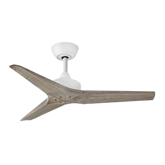
  • Page 1 INDOOR/OUTDOOR FAN 44"CHISEL ™ DC MOTOR DAMP CEILING FAN INSTRUCTION MANUAL...
  • Page 2 SO WE’RE HERE IF YOU HAVE A QUESTION, NEED SOME HELP OR WANT TO CHAT ABOUT OUR PRODUCTS. SEND SUGGESTIONS OUR WAY TOO—WE’RE ALWAYS LOOKING TO MAKE YOUR EXPERIENCE WITH HINKLEY A POSITIVE ONE. > SERVICE@HINKLEY.COM > 800.HINKLEY > LET’S SEE THAT HINKLEY STYLE @HINKLEY...
  • Page 3: Table Des Matières

    HANGING THE FAN SMART BY BOND ELECTRICAL CONNECTIONS FINISHING THE INSTALLATION BLADE ATTACHMENT NOTE: Limit one fan per power circuit. WARNING: Read and follow these instructions carefully and be mindful of all warnings shown throughout. ©2019 Hinkley Lighting, Inc. | hinkley.com |...
  • Page 4 The fan can be made to work immediately after installation - the bearings are adequately charged with grease so that, under normal conditions, further lubrication should not be necessary for the life of the fan. To operate the reverse function on this fan, press the reverse button while the fan is running. NOTE: Limit one fan per power circuit. | hinkley.com...
  • Page 5: Important Safety Precautions

    TOOLS & MATERIALS REQUIRED • PHILLIPS SCREWDRIVER • FLAT SCREWDRIVER • WRENCH OR PLIERS • WIRE CUTTER • STEPLADDER • WIRING SUPPLIES AS REQUIRED BY ELECTRICAL CODE ©2019 Hinkley Lighting, Inc. | hinkley.com |...
  • Page 6: Unpacking Your Fan

    Safety cable hardware MH903744FGT (wood screw, at washer) Bracket Mounting Hardware (wood screws, screws, lock washers, star washers, at washers) Balance Kit NOTE: Design of parts shown above may look slightly di erent for your speci c model of fan. | hinkley.com...
  • Page 7: Preparation

    Loosen screw with key slot and remove canopy. Flat Washer Spring Washer Attach hanging bracket to outlet box using screws provided with the outlet box. Outlet Box Screw Fig. 1 ©2019 Hinkley Lighting, Inc. | hinkley.com |...
  • Page 8: Hanging The Fan

    Tighten security set screws against downrod using a large at blade screwdriver to ensure a tight t against downrod. Tighten nuts against mounting collar. Downrod Mounting Collar Security Screws Cotter Pin Downrod Pin Top of Fan Body Fig. 2 | hinkley.com...
  • Page 9 Safety Cable Loop of the cable into the clamp and pull as much cable through as Wood Screw possible. Firmly tighten screw in the clamp. Cut o excess cable. And Washer Safety Cable Fig. 4 | hinkley.com ©2019 Hinkley Lighting, Inc.
  • Page 10: Electrical Connections

    Connect the COPPER building ground wire to the YELLOW/GREEN fan ORANGE(to motor) ground wire. Also connect the two GREEN wires (from fan) to building ground wire. GRAY (to motor) YELLOW (to motor) YELLOW (motor) GRAY (motor) Hanger bracket ORANGE (motor) Receiver Fig. 1 Fig. 2 hinkley.com...
  • Page 11: Finishing The Installation

    Make sure the hook on the hanging bracket properly sits in the groove in the hanger ball before attaching the canopy to the bracket by turning the housing until it drops into place. ©2019 Hinkley Lighting, Inc. | hinkley.com |...
  • Page 12: Blade Attachment

    Use a large at blade screwdriver for nal tightening to fully compress the washers. This will help ensure proper alignment of the blades and noise-free, wobble-free running. Blades Flat Washers Lock Washers Screws | hinkley.com...
  • Page 13: Installing The Wall Control

    Install the wall transmitter on the existing wall outlet box using the screws provided. Attached the wall plate with the mounting screws to nish the installation. (Fig. 2) Transmitter Decorative Wall Plate Fig. 2 ©2019 Hinkley Lighting, Inc. | hinkley.com |...
  • Page 14: Operation

    (suggested speed IV) Light button: Power switch This button is to control optional light. Switch the "D" and "ON" dip switch on the front of transmitter to decide the light in Fig. 2 "ON/OFF" or "Dimmable" condition. | hinkley.com...
  • Page 15 An UPWARD air ow moves warmer air o the ceiling area as shown in Figure 4. This allows you to set your heating unit on a cooler setting without a ecting your comfort. SUMMER MODE WINTER MODE (COUNTERCLOCKWISE DIRECTION) (CLOCKWISE DIRECTION) Fig. 3 Fig. 4 ©2019 Hinkley Lighting, Inc. | hinkley.com |...
  • Page 16: Care And Cleaning

    2. If the blade wobble is still noticeable, interchanging two adjacent (side by side) blades can redistribute the weight and possibly result in smoother operation. 3. Check to assure all dowrods to motor hardware and/or hanger ball are tight. 4. Make sure ceiling box is secure. | hinkley.com...
  • Page 17: Energy Guide

    RPMs SMART BY BOND HINKLEY SMART FAN OPTIONS (SOLD SEPARATELY): In addition to the included wall control, you can control your Hinkley fan through the Bond app using the smart technology accessory controls SOLD SEPARATELY. • To use the app, download it for free from the App Store or Google Play.
  • Page 18 HINKLEY IS PROUD TO PROVIDE YOU WITH CEILING FAN PRODUCTS THAT ENHANCE YOUR SPACE WITH COMFORT, PURPOSE AND STYLE. AS A FAMILY COMPANY, WE ARE COMMITTED TO DESIGN, PERFORMANCE AND QUALITY, AND WHAT’S IMPORTANT TO YOU IS PARAMOUNT TO US.
  • Page 19 GLOBAL HEADQUARTERS 33000 Pin Oak Parkway | Avon Lake, Ohio 44012 T (440) 653 5500 | F (440) 653 5555 | hinkley.com...
  • Page 20 VENTILADOR INTERIOR / EXTERIOR 44"CHISEL™ DC MOTOR DAMP MANUAL DE INSTRUCCIONES PARA VENTILADORES DE TECHO...
  • Page 21 Si no está familiarizado o no se siente cómodo con el cableado, comuníquese con un electricista calificado. Si necesita asistencia adicional o tiene alguna pregunta, comuníquese con nosotros. Para obtener información sobre la garantía, visite hinkley.com.
  • Page 22 TERMINANDO LA INSTALACIÓN ACCESORIO DE HOJA NOTA: Límite de un ventilador por circuito de alimentación ADVERTENCIA: Lea y siga estas instrucciones cuidadosamente y tenga en cuenta todas las advertencias que se muestran a lo largo.. ©2019 Hinkley Lighting, Inc. | hinkley.com |...
  • Page 23: Instrucciones Generales De Instalación Y

    útil del ventilador. Para operar la función de retroceso en este ventilador, presione el botón de retroceso mientras el ventilador está funcionando. NOTA: Límite de un ventilador por circuito de alimentación. | hinkley.com...
  • Page 24: Precauciones Importantes De Seguridad

    HERRAMIENTAS Y MATERIALES REQUERIDOS • DESTORNILLADOR PHILLIPS • DESTORNILLADOR PLANO • LLAVE O ALICATES • CORTADOR DE CABLES • ESCALERA DE TIJERA • SUMINISTROS DE CABLEADO SEGÚN REQUERIDO POR CÓDIGO ELÉCTRICO ©2019 Hinkley Lighting, Inc. | hinkley.com |...
  • Page 25: Desembalaje Su Ventilador

    Hardware de montaje del soporte (tornillos para madera, tornillos, arandelas de seguridad, arandelas de estrella, arandelas planas) Kit de NOTA: El diseño de las piezas que se muestran arriba puede verse equilibrio ligeramente diferente para su modelo específico de ventilador. | hinkley.com...
  • Page 26: Preparación

    Tornillo de Fije el soporte para colgar a la caja de salida con los tornillos que se caja de proporcionan con la caja de salida. salida Fig. 1 ©2019 Hinkley Lighting, Inc. | hinkley.com |...
  • Page 27: Colgando El Ventilador

    Apriete las tuercas contra el collar de montaje. Bajar Collar de Tornillos de montaje seguridad Pasador de chaveta Parte superior Pasador de del cuerpo del varilla ventilador Fig. 2 | hinkley.com...
  • Page 28 Tornillo y arandela del cable en la abrazadera y pase la mayor cantidad de cable de madera posible. Apriete firmemente el tornillo de la abrazadera. Corte el Cable de Fig. 4 cable sobrante. seguridad | hinkley.com ©2019 Hinkley Lighting, Inc.
  • Page 29 AMARILLO / VERDE. AMARILLO (al motor) • También conecte los dos cables VERDES (del ventilador) al cable de tierra del edificio. AMARILLO (motor) GRIS (motor) ROJO (motor) Soporte de BLANCO (motor) suspensión AZUL (motor) Ventilador Receptor Fig. 2 Fig. 1 hinkley.com...
  • Page 30 Asegúrese de que el gancho del soporte para colgar se asiente correctamente en la ranura de la bola de suspensión antes de sujetar el dosel al soporte girando la carcasa hasta que encaje en su lugar. ©2019 Hinkley Lighting, Inc. | hinkley.com |...
  • Page 31 Utilice un destornillador grande de punta plana para el ajuste final para comprimir completamente las arandelas. Esto ayudará a garantizar la alineación adecuada de las palas y un funcionamiento sin ruidos ni oscilaciones. Cuchillas Arandelas Arandelas de seguridad planas Empulgueras | hinkley.com...
  • Page 32 Instale el transmisor de pared en la caja de salida de pared existente usando los tornillos provistos. Fije la placa de pared con los tornillos de montaje para finalizar la instalación. (Figura Transmisora Placa de pared decorativa Fig. 2 ©2019 Hinkley Lighting, Inc. | hinkley.com |...
  • Page 33 Botón de luz: Este botón es para controlar la luz Fig. 2 opcional. Cambie el interruptor DIP "D" y "ON" en la parte frontal del transmisor para decidir la luz en la condición "ON / OFF" o "Dimmable". | hinkley.com...
  • Page 34 Un flujo de aire HACIA ARRIBA mueve el aire más caliente del área del techo como se muestra en la Figura 4. Esto le permite configurar su unidad de calefacción en una configuración más fría sin afectar su comodidad. MODO INVIERNO MODO VERANO (SENTIDO DE LAS (DIRECCIÓN EN SENTIDO AGUJAS DEL RELOJ)) Fig. 3 Fig. 4 ANTIHORARIO) ©2019 Hinkley Lighting, Inc. | hinkley.com |...
  • Page 35 3. Verifique para asegurarse de que todas las varillas de los accesorios del motor y / o la bola de suspensión estén apretadas. 4. Asegúrese de que la caja de techo esté segura. | hinkley.com...
  • Page 36 INTELIGENTE POR BOND OPCIONES DE VENTILADOR INTELIGENTE HINKLEY SE VENDE POR SEPARADO: Además del control de pared incluido, puede controlar su ventilador Hinkley a través de la aplicación Bond. • Para usar la aplicación, descárguela de forma gratuita desde App Store o Google Play.
  • Page 37 HINKLEY SE ENCUENTRA ORGULLOSO DE PROPORCIONARLE PRODUCTOS PARA VENTILADORES DE TECHO QUE MEJORAN SU ESPACIO CON COMODIDAD, PROPÓSITO Y ESTILO. COMO EMPRESA FAMILIAR, ESTAMOS COMPROMETIDOS CON EL DISEÑO, EL RENDIMIENTO Y LA CALIDAD, Y LO QUE ES IMPORTANTE PARA USTED ES PARAMOUNT PARA NOSOTROS.
  • Page 38 GLOBAL HEADQUARTERS 33000 Pin Oak Parkway | Avon Lake, Ohio 44012 T (440) 653 5500 | F (440) 653 5555 | hinkley.com...
  • Page 39 VENTILATEUR INTÉRIEUR / EXTÉRIEUR 44"CHISEL™ DC MOTOR DAMP MANUEL D'UTILISATION DU VENTILATEUR DE PLAFOND...
  • Page 40 NOUS SOMMES ICI SI VOUS AVEZ UNE QUESTION, BESOIN D'UNE AIDE OU VOULEZ CHAT SUR NOS PRODUITS. ENVOYER DES SUGGESTIONS NOTRE FAÇON AUSSI - NOUS CHERCHONS TOUJOURS À FAIRE DE VOTRE EXPÉRIENCE AVEC HINKLEY UNE POSITIVE. > SERVICE@HINKLEY.COM > 800.HINKLEY >...
  • Page 41 SUSPENDRE LE VENTILATEUR CONNECTIONS ELECTRIQUES FIN DE L'INSTALLATION ATTACHEMENT DE LA LAME REMARQUE: Limite d'un ventilateur par circuit d'alimentation ATTENTION: AVERTISSEMENT: lisez et suivez attentivement ces instructions et tenez compte de tous les avertissements indiqués. ©2019 Hinkley Lighting, Inc. | hinkley.com |...
  • Page 42: Instructions Générales D'installation

    Pour activer la fonction d'inversion sur ce ventilateur, appuyez sur le bouton d'inversion pendant que le ventilateur fonctionne. REMARQUE: Limite d'un ventilateur par circuit d'alimentation | hinkley.com...
  • Page 43: Précautions De Sécurité Importantes

    être intégrés à ce produit. Ces facteurs doivent être fournis par la ou les personnes installant, prenant soin et utilisant l'appareil. OUTILS ET MATÉRIAUX REQUIS • TOURNEVIS CRUCIFORME • TOURNEVIS PLAT • CLÉ OU PINCE • COUPE-FIL • ESCABEAU • FOURNITURES DE CÂBLAGE COMME REQUIS PAR LE CODE ÉLECTRIQUE ©2019 Hinkley Lighting, Inc. | hinkley.com |...
  • Page 44: Déballage De Votre Fan

    (vis à bois, rondelle plate) Matériel de montage du support (vis à bois, vis, rondelles de blocage, rondelles en étoile, rondelles plates) Kit d'équilibre REMARQUE: La conception des pièces illustrées ci-dessus peut être légèrement différente pour votre modèle de ventilateur spécifique. | hinkley.com...
  • Page 45: Préparation

    Rondelle à ressort Vis de boîte Fixez le support de suspension à la boîte de sortie à l'aide des vis fournies de sortie avec la boîte de sortie. Fig. 1 ©2019 Hinkley Lighting, Inc. | hinkley.com |...
  • Page 46: Suspendre Le Ventilateur

    à lame plate pour assurer un ajustement serré contre la tige descendante. Serrez les écrous contre le collier de montage. Collier de montage Vis de sécurité Goupille Goupille de tige Haut du corps du descendante ventilateur Fig. 2 | hinkley.com...
  • Page 47 Faites passer l'extrémité du câble dans la pince et tirez et rondelle autant de câble que possible. Serrez fermement la vis du collier. Couper le câble en excès. Câble de Fig. 4 sécurité | hinkley.com ©2019 Hinkley Lighting, Inc.
  • Page 48: Connections Electriques

    • Connectez également les deux fils VERT (du ventilateur) au fil de terre du bâtiment. ROUGE (aumoteur) GRIS (au moteur) JAUNE (au moteur) JAUNE (moteur) GRIS (moteur) ROUGE (moteur) Support de suspension BLANC (moteur) BLEU (moteur) Ventilateur Destinataire Fig. 2 Fig. 1 hinkley.com...
  • Page 49: Fin De L'installation

    Assurez-vous que le crochet du support de suspension se trouve correctement dans la rainure de la boule de suspension avant de fixer la verrière au support en tournant le boîtier jusqu'à ce qu'il se mette en place. ©2019 Hinkley Lighting, Inc. | hinkley.com |...
  • Page 50: Attachement De La Lame

    à lame plate pour le serrage final afin de comprimer complètement les rondelles. Cela aidera à assurer un alignement correct des lames et un fonctionnement sans bruit et sans oscillation. Lames Rondelles Rondelles de blocage plates Des vis | hinkley.com...
  • Page 51: Installation De La Commandemurale

    Fig. 1 Installez l'émetteur mural sur la boîte murale existante à l'aide des vis fournies. Fixez la plaque murale avec les vis de montage pour terminer l'installation. (Fig.2) Plaque murale Émettrice décorative Fig. 2 ©2019 Hinkley Lighting, Inc. | hinkley.com |...
  • Page 52: Opération

    (vitesse suggérée IV) Interrupteur Bouton d'éclairage: Ce bouton sert à contrôler la lumière en Fig. 2 option. Mettez l'interrupteur DIP "D" et "ON" à l'avant de l'émetteur pour décider de la lumière en "ON / OFF" ou "Dimmable" | hinkley.com...
  • Page 53 Un flux d'air VERS LE HAUT déplace l'air plus chaud hors de la zone du plafond, comme illustré à la figure 4. Cela vous permet de régler votre unité de chauffage sur un réglage plus frais sans affecter votre confort. MODE HIVER MODE ÉTÉ (DANS LE SENS DES AIGUILLES D'UNE Fig. 3 Fig. 4 (DIRECTION CONTRE-HORLOGE) MONTRE) ©2019 Hinkley Lighting, Inc. | hinkley.com |...
  • Page 54: Entretien Et Nettoyage

    éventuellement entraîner un fonctionnement plus fluide. 3. Vérifiez que toutes les tiges de fixation de la quincaillerie du moteur et / ou de la boule de suspension sont bien serrées. 4. Assurez-vous que le boîtier de plafond est sécurisé. | hinkley.com...
  • Page 55: Caractéristiques

    Le débit d'air affiché est une moyenne pondérée des pieds cubes hauts et bas par minute, basée sur la tige de descente SMART BY BOND OPTIONS DE VENTILATEUR HINKLEY SMART VENDU SÉPARÉMENT: En plus du contrôle mural inclus, vous pouvez contrôler votre ventilateur Hinkley via l'application Bond. • Pour utiliser l'application, téléchargez-la gratuitement depuis l'App Store ou Google Play.
  • Page 56 HINKLEY EST FIER DE VOUS FOURNIR DES PRODUITS POUR VENTILATEURS DE PLAFOND QUI AMÉLIORENT VOTRE ESPACE AVEC CONFORT, BUT ET STYLE. EN TANT QU'ENTREPRISE FAMILIALE, NOUS SOMMES ENGAGÉS À LA CONCEPTION, À LA PERFORMANCE ET À LA QUALITÉ, ET CE QUI EST IMPORTANT POUR VOUS EST PARAMOND POUR NOUS.
  • Page 57 GLOBAL HEADQUARTERS 33000 Pin Oak Parkway | Avon Lake, Ohio 44012 T (440) 653 5500 | F (440) 653 5555 | hinkley.com...

Ce manuel est également adapté pour:

Chisel 903744fgt-ndd

Table des Matières