Publicité
Les langues disponibles
Les langues disponibles
Liens rapides
G e n e r a l i n f o r m a t i o n :
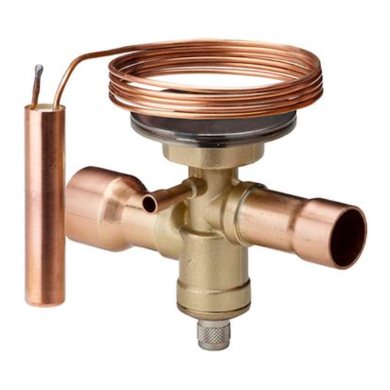
TIH-...FLR series of Thermo™-Expansion Valves are
designed for air conditioning, heat pumps and
commercial refrigeration systems having R290 as
refrigerant. The TIH-...FLR is ideal for those
applications
requiring
hermetic/
combined with stable and accurate control over wide
load and evaporating temperature ranges.
TIH-...-FLR are not in scope of ATEX directive
2014/34/EU as they do not incorporate an own source
of ignition.
TIH-...FLR must be installed in an appropriate housing
to protect them from mechanical damage or shock.
S a f e t y i n s t r u c t i o n s :
• Read operating instructions thoroughly. Failure
to comply can result in device failure, system
damage or personal injury.
• According to EN 13313 it is intended for use by
persons having the appropriate knowledge and
skill.
• Flammable refrigerants require special handling
and care due to its flammability. Sufficient
ventilation is required during service of the
system. Contact with rapidly expanding gases can
cause frostbite and eye damage. Proper protective
equipment (gloves, eye protection, etc.) must be
used.
• Ensure that the system is correctly labeled with
applied refrigerant type and a warning for
explosion risk.
• In a severely contaminated system, avoid
breathing acid vapors and avoid contact with skin
from contaminated refrigerant / lubricants.
Failure to do so could result in injury.
• Before opening any system make sure pressure in
system is brought to and remains at atmospheric
pressure.
• Do
not release any
refrigerant into the
atmosphere!
• Do not exceed the specified maximum ratings for
pressure and temperature.
• Do not use any other fluid media without prior
approval of EMERSON.
• Ensure that design, installation and operation are
according
to
European
standards/regulations.
M o u n t i n g l o c a t i o n :
• Valves may be installed in any position, but should
be located as close as possible to the distributor or
evaporator inlet.
• Fig. 1 shows Heat pump application incorporating
two valves with location of bulbs.
I n s t a l l a t i o n :
Warning: Do not bend capillary tube at interface
to head of valve. Allowed: distance N (10 mm) and
radius R (5 mm).
Fig. 3
Emerson Climate Technologies GmbH
Am Borsigturm 31 I 13507 Berlin I Germany
FLR_OI_EN_DE_FR_ES_IT_RU_0220_R04_866917.docx
Operating instruction
Thermo™-Expansion Valve
TIH-...FLR Series for R290
• Securely fasten the bulb with straps provided.
Insulate bulb with a suitable material. The location of
bulb on suction line is dependent to size of suction
line. (see Fig. 4)
• Ensure that the capillary is mounted without tension,
compact
size
always leave the capillary a bit loose and it should
not be strangulated. Maintain also a clearance from
the capillary to other objects. The capillary should
not be in contact with other objects.
• Connect equalizer line (1/4" or 6 mm tube) to valve
and suction line. Be sure that the external equalizer
line cannot siphon oil from the suction line. (Fig.5)
Recommended external pipe connections:
Nominal pipe
connection
1/4"
3/8"
1/2"
6 mm
10 mm
12 mm
16 mm (5/8")
B r a z i n g : ( F i g . 2 )
• Perform and consider the brazing joint as per
EN 14324.
• Before and after brazing clean tubing and brazing
joints.
• To avoid oxidization, it is advised to purge the
system with an inert gas such as nitrogen while
brazing.
• Do not exceed the max. body temperature of
120 C!
• Minimize vibrations in the piping lines by
appropriate solutions.
P r e s s u r e T e s t :
After completion of installation, a pressure test must be
carried out as follows:
- according to EN 378 for systems which must
comply with European pressure equipment
directive 2014/68/EU.
- Max Test pressure: 38.5 bar
W a r n i n g :
• Failure to do so could result in loss of refrigerant
and
national
and personal injury.
• The pressure test must be conducted by skilled
persons with due respect regarding the danger
related to pressure.
T i g h t n e s s T e s t :
Conduct a tightness test according to EN 378-2 with
appropriate equipment and method to identify tightness
of external joints. The allowable leakage rate must be
according system manufacturer's specification.
O p e r a t i o n :
• Check for leaks, sufficient refrigerant charge and be
sure no flash gas is present before attempting to
check valve operation.
• Check/measure superheat.
www.climate.emerson.com/en-gb
F a c t o r y s e t t i n g s :
The table below provides the factory setting position of
superheat adjusting stem and shows the number of turns
clockwise
counterclockwise
Charge
Code
W a r n i n g :
There are max. 12 turns on the adjustment stem
(from left stop to right stop). When stop is reached,
any further turning will damage the valve.
Fig. 7
Outside diameter
Min. (mm) Max.(mm)
6.30
6.38
9.47
9.55
12.62
12.73
5.95
6.05
9.95
10.05
11.96
12.05
15.95
16.05
S u p e r h e a t A d j u s t m e n t :
If the superheat must be adjusted for the application
proceeds as follows:
1. Remove seal cap from bottom of valve.
2. Turn the adjustment screw clockwise to increase the
superheat
superheat.
Changes in Superheat (K) per stem turn depending
on evaporating temperature and refrigerant:
Refrigerant
R290
As much as 15 minutes are required for the system to
stabilize after the adjustment is made.
3. Determine superheat "sh" according to Fig. 6.
4. Replace and tighten seal cap (hand tight).
5.Check for external leakage.
S e r v i c e / M a i n t e n a n c e :
• Defective TIH-...FLR must be replaced, they cannot
be repaired.
• Before any debrazing ensure that the flammable
refrigerant is pumped out of the system and the room
around the system is well vented so no refrigerant
left.
T e c h n i c a l D a t a :
Max. working pressure PS
Factory test pressure PT
Medium temperature TS
Dimensions
Medium compatibility
when
adjusting
stem
fully
Number of
Charge
Number of
turns (360°)
Code
turns (360°)
P0/P2
+4
Note:
+ = Clockwise rotation
- = Counterclockwise rotation
and
counterclockwise
to
Evaporating temperature (°C)
-30
-20
-10
3.6
2.7
2.1
-45...+75°C
Date: 17.04.2019
open
decrease
0
1.7
35 bar
38.5 bar
Fig. 8
R290
TIH-
Publicité

Manuels Connexes pour Emerson Alco Controls Thermo TIH Serie


Sommaire des Matières pour Emerson Alco Controls Thermo TIH Serie
- Page 1 Medium temperature TS -45…+75°C Fig. 3 Dimensions Fig. 8 • Check/measure superheat. Medium compatibility R290 Emerson Climate Technologies GmbH www.climate.emerson.com/en-gb Date: 17.04.2019 Am Borsigturm 31 I 13507 Berlin I Germany TIH- FLR_OI_EN_DE_FR_ES_IT_RU_0220_R04_866917.docx...
- Page 2 • Die angegebenen Grenzwerte für Druck und überschreiten! Verdampfungstemperatur und dem Kältemittel: Temperatur nicht überschreiten. • Vibrationen auf den Rohrleitungen sind durch Verdampfungstemperatur (°C) • Es dürfen nur von EMERSON freigegebene entsprechende Maßnahmen zu minimieren. Kältemittel Medien eingesetzt werden • Konstruktion, Installation und Betrieb der R290...
- Page 3 Betriebsanleitung Thermo™-Expansionsventile Baureihe TIH-…FLR für R290 Emerson Climate Technologies GmbH www.climate.emerson.com/en-gb Date: 17.04.2019 Am Borsigturm 31 I 13507 Berlin I Germany TIH- FLR_OI_EN_DE_FR_ES_IT_RU_0220_R04_866917.docx...
- Page 4 • Ne pas utiliser un autre fluide que ceux indiqués Un temps de 15 min est nécessaire après le réglage répondre à la Directive Pression Européenne pour sans l’approbation obligatoire d’EMERSON. pour obtenir une stabilisation. les équipements 2014/68/EU. • S'assurer que la conception, l'installation et la 3.
- Page 5 • No use ningún fluido que no haya sido empleado: previamente aprobado por EMERSON. Temp. de evaporación (°C) • Compruebe que el diseño, la instalación, y el P r u e b a d e p r e s i ó n :...
- Page 6 Istruzioni operative Valvola d’espansione termostatica TIH-…FLR per R290 Emerson Climate Technologies GmbH www.climate.emerson.com/en-gb Date: 17.04.2019 Am Borsigturm 31 I 13507 Berlin I Germany TIH- FLR_OI_EN_DE_FR_ES_IT_RU_0220_R04_866917.docx...
- Page 7 Massima pressione di esercizio PS 35 bar Pressione di prova in produzione PT 38.5 bar Temperatura del fluido TS -45…+75°C Dimensioni Fig. 8 Compatibilità del fluido R290 Emerson Climate Technologies GmbH www.climate.emerson.com/en-gb Date: 17.04.2019 Am Borsigturm 31 I 13507 Berlin I Germany TIH- FLR_OI_EN_DE_FR_ES_IT_RU_0220_R04_866917.docx...
- Page 8 Руководство по эксплуатации Термо-расширительные клапаны TIH-…FLR для R290 Emerson Climate Technologies GmbH www.climate.emerson.com/en-gb Date: 17.04.2019 Am Borsigturm 31 I 13507 Berlin I Germany TIH- FLR_OI_EN_DE_FR_ES_IT_RU_0220_R04_866917.docx...
- Page 9 Fig. 8 попыткой работы с клапаном, что в настоящий Совместимость R290 момент на вход в клапан поступает жидкий Маркировка хладагент. • Измерьте/проверьте перегрев. Emerson Climate Technologies GmbH www.climate.emerson.com/en-gb Date: 17.04.2019 Am Borsigturm 31 I 13507 Berlin I Germany TIH- FLR_OI_EN_DE_FR_ES_IT_RU_0220_R04_866917.docx...
- Page 10 TIH-..6-FLR 43.5 TIH-..7-FLR TIH-..8-FLR 12 / 1/2" 16 / 5/8" 6 / 1/4" 13.1 10.4 TIH-..9-FLR TIH-..A-FLR (mm/мм) Charge Ø S P0/P2 15.9 Emerson Climate Technologies GmbH www.climate.emerson.com/en-gb Date: 17.04.2019 Am Borsigturm 31 I 13507 Berlin I Germany TIH- FLR_OI_EN_DE_FR_ES_IT_RU_0220_R04_866917.docx...